EP0651464A2 - Schneidklemmverbindung mit Unterstützungsfeder - Google Patents
Schneidklemmverbindung mit Unterstützungsfeder Download PDFInfo
- Publication number
- EP0651464A2 EP0651464A2 EP94307444A EP94307444A EP0651464A2 EP 0651464 A2 EP0651464 A2 EP 0651464A2 EP 94307444 A EP94307444 A EP 94307444A EP 94307444 A EP94307444 A EP 94307444A EP 0651464 A2 EP0651464 A2 EP 0651464A2
- Authority
- EP
- European Patent Office
- Prior art keywords
- terminal
- contact
- idc
- spring
- section
- Prior art date
- Legal status (The legal status is an assumption and is not a legal conclusion. Google has not performed a legal analysis and makes no representation as to the accuracy of the status listed.)
- Granted
Links
- 230000000295 complement effect Effects 0.000 claims abstract description 13
- 230000013011 mating Effects 0.000 claims abstract description 7
- 238000006073 displacement reaction Methods 0.000 claims description 5
- 238000009413 insulation Methods 0.000 claims description 5
- 230000014759 maintenance of location Effects 0.000 claims description 5
- 238000005452 bending Methods 0.000 claims description 2
- 238000005728 strengthening Methods 0.000 claims 1
- 239000000463 material Substances 0.000 abstract description 8
- 230000003014 reinforcing effect Effects 0.000 abstract description 3
- 238000000034 method Methods 0.000 description 7
- 239000002184 metal Substances 0.000 description 5
- 230000007423 decrease Effects 0.000 description 2
- 229910000831 Steel Inorganic materials 0.000 description 1
- 230000000630 rising effect Effects 0.000 description 1
- 239000010959 steel Substances 0.000 description 1
Images


Classifications
-
- H—ELECTRICITY
- H01—ELECTRIC ELEMENTS
- H01R—ELECTRICALLY-CONDUCTIVE CONNECTIONS; STRUCTURAL ASSOCIATIONS OF A PLURALITY OF MUTUALLY-INSULATED ELECTRICAL CONNECTING ELEMENTS; COUPLING DEVICES; CURRENT COLLECTORS
- H01R4/00—Electrically-conductive connections between two or more conductive members in direct contact, i.e. touching one another; Means for effecting or maintaining such contact; Electrically-conductive connections having two or more spaced connecting locations for conductors and using contact members penetrating insulation
- H01R4/24—Connections using contact members penetrating or cutting insulation or cable strands
- H01R4/2416—Connections using contact members penetrating or cutting insulation or cable strands the contact members having insulation-cutting edges, e.g. of tuning fork type
- H01R4/2445—Connections using contact members penetrating or cutting insulation or cable strands the contact members having insulation-cutting edges, e.g. of tuning fork type the contact members having additional means acting on the insulation or the wire, e.g. additional insulation penetrating means, strain relief means or wire cutting knives
- H01R4/2462—Connections using contact members penetrating or cutting insulation or cable strands the contact members having insulation-cutting edges, e.g. of tuning fork type the contact members having additional means acting on the insulation or the wire, e.g. additional insulation penetrating means, strain relief means or wire cutting knives the contact members being in a slotted bent configuration, e.g. slotted bight
-
- H—ELECTRICITY
- H01—ELECTRIC ELEMENTS
- H01R—ELECTRICALLY-CONDUCTIVE CONNECTIONS; STRUCTURAL ASSOCIATIONS OF A PLURALITY OF MUTUALLY-INSULATED ELECTRICAL CONNECTING ELEMENTS; COUPLING DEVICES; CURRENT COLLECTORS
- H01R13/00—Details of coupling devices of the kinds covered by groups H01R12/70 or H01R24/00 - H01R33/00
- H01R13/02—Contact members
- H01R13/15—Pins, blades or sockets having separate spring member for producing or increasing contact pressure
- H01R13/17—Pins, blades or sockets having separate spring member for producing or increasing contact pressure with spring member on the pin
Definitions
- This invention relates to an electrical terminal having an insulation displacement contact section reinforced with a back-up spring.
- Insulation displacement contacts are increasingly common in the electrical industry because they allow simultaneous termination of a plurality of terminals to respective conducting wires in a simple automated procedure whereby the wires do not need to be stripped and are simply forced into IDC slots with a stuffer tool.
- IDC Insulation displacement contacts
- the conductivity of the metal from which the contact is formed is largely determined by the contact pressure exerted therebetween which in turn is determined by the spring forces that engage the contact surfaces together.
- the sheet metal commonly used for producing electrical terminals usually decreases in resiliency as the conductivity and ductility increases.
- the creep properties i.e. stress relaxation of the material over time and as a function of temperature and stress. The latter is aggravated by the requirement to produce compact terminals having small material cross-sections engendering high resistance and therefore high temperatures during the passage of electrical current, whereby the high temperatures greatly increase the rate of creep of the metal.
- an electrical terminal having a contact body comprising a contact section and a wire receiving section, the wire receiving section comprising insulation displacement contact support walls having opposed edges forming one or more slots for receiving the conducting wire, characterized in that the terminal also has a separate back-up spring attached to the support walls for resilient biasing thereof together against outward forces of the conducting wire positioned in the slots. Further objects have been achieved by providing the aforementioned terminal with a back-up spring having a contact spring portion for biasing the complementary terminal against the contact body.
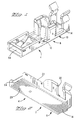
- an electrical terminal 2 comprising a contact section 4 for mating with a complementary male tab terminal 102, and a wire receiving portion 8 for connection to a conducting wire (shown in outline 9 in Figure 7).
- the terminal 2 comprises a contact body 10 stamped and formed from conductive sheet metal, and a back-up spring 12 stamped and formed from resilient sheet metal.
- the contact body 10 comprises a base wall 14 extending longitudinally from a mating end 16 of the terminal to a wire receiving end 18 and having in the contact section 4, embossed contact protrusions 20.
- the contact section 4 also comprises side walls 22 extending orthogonally from lateral edges of the base 14 and having back-up spring forward and rear support cavities 24, 26 respectively.
- the contact body 10 comprises an insulation displacement contact (IDC) section 28 comprising a pair of opposed support walls 30 extending orthogonally from the base 14 and having central portions 32 attached to lateral edges of the base 14, and arcuate wall portions 34 bent towards each other such that edges 36 thereof form a slot 37 for receiving the conducting wire therebetween.
- IDC insulation displacement contact
- the support walls 30 At a top edge 39 of the support walls 30 are recesses 38 for receiving mounting portions of the back-up spring.
- Proximate the wire receiving end 18 are deformable lateral strain relief members 40 forse- curely holding the conducting wire to the terminal 2.
- the back-up spring 12 is shown comprising a contact spring portion 42 and an IDC back-up portion 44 integral therewith via a central bridge portion 46.
- the contact spring portion 42 comprises a pair of resilient inwardly bowed beams 48 supported on either end to transverse support beams 50, 52, respectively that span from side wall 22 to side wall 22 of the contact body 10 when assembled thereto, finding support in the cavities 24, 26 respectively.
- the contact spring portion 42 further comprises a centrally and forwardly located oblique locking lance 53 for retention of the terminal 2 in a connector housing 55 (see Figure 9).
- the IDC back-up portion 44 comprises a U-shaped member 54 having an arcuate base portion 56 and side walls 58 extending into bent over mounting tabs 60 at their top ends for clasping over the recesses 38 of the contact body support walls 30.
- the rib 62 is disposed transversely to a portion of the conducting wire that is forced into the IDC slots 36 of the contact body 10.
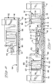
- the back-up spring 12 is shown assembled to the contact body 10 whereby ends 63, 65 of the support beams 50, 52 are located in the contact body cavities 24, 26 respectively, the contact spring portion 42 thereby spanning across the contact body 10. Due to the bowed resilient contact beams 48, an entry funnel 64 is formed for receiving and guiding a tab 104 of the complementary male tab terminal 102.
- the contact beams 48 have a widened central portion 66 that purports to evenly distribute the internal moments within the beam thereby ensuring substantially equivalent bending stresses therealong for high resiliency yet optimal flexibility and reduced risk of buckling. Supporting of the resilient beams 48 at both ends and bowing them inwards, not only provides the entry funnel 64, but also a very high spring strength thereby creating high contact pressure between the mating terminals 2, 102.
- the IDC back-up portion 44 of the back-up spring 12 is positioned between the contact body support walls 30 and disposed centrally between the pair of contact slots 37, whereby the U-shaped section 54 can be slightly prestressed such that it tends to pull the contact body support walls 30 together in opposition to outward forces of a conducting wire urged in the IDC slots 37.
- the reinforcing rib 62 further enhances the spring strength of the IDC back-up portion 44 such that it is sufficiently strong to ensure that the IDC contact edges 36 are always biased towards each other with sufficient pressure against the conducting wire, even after operating temperatures and stresses cause relaxation of the contact body material.
- the contact body material can therefore be chosen for optimal conductivity and the back-up spring 12 with optimal spring properties such that the contact body 10 can support very high currents, yet have IDC contacts ideally adapted for cost-effective, automated assembly in connector housings and connection to conducting wires.
- Disposition of the IDC back-up portion 44 between the supporting walls 30 of the contact body further increases the compactness of the terminal, and also facilitates the assembly procedure of the back-up spring as both the contact spring portions 42 and IDC back-up portions 44 are assembled from the top of the contact body (as opposed to being wrapped around).
- Use of the contact spring portion 42 as a top wall that provides high spring forces not only leads to a very compact disposition, but also ensures reliable high contact pressure between the contact protrusions 20 and the complementary male tab 104.
- a complementary male terminal 102 matable with the receptacle terminal 2 comprising a male tab 104, a retention section 106 and a wire receiving section 108 that is identical to the wire receiving section 8 of the receptacle terminal 2 and shall therefore not be further described.
- the complementary male terminal 102 also comprises a contact body 110 having a base wall 114 from which the tab 104 extends.
- the retention section 106 comprises side walls 122 extending from lateral edges of the base wall 114 and having cavities 126 therethrough for supporting a support beam 150 having a resilient locking lance 153 extending therefrom for retaining the terminal 102 within a connector housing 132.
- the receptacle terminal 2 and complementary male terminal 102 are shown assembled in their respective connector housings 55, 155 and mated together.
- the housings 55, 155 have slots 68, 168 allowing access for the conducting wire to be positioned over and aligned with the pair of IDC slots 37, and subsequently stuffed therebetween with a stuffer tool adapted therefor in an automated procedure.
- the latter therefore allows the terminals 2, 102 to be assembled to the connector housings 55, 155 prior to assembly with the conducting wires, and then at a later stage feeding and stuffing the wires into the IDC contacts without stripping the ends.
- the assembly procedure can therefore be fully automated.
- the terminal is compact yet able to carry high currents and is furthermore adapted to cost-effective automated assembly harness procedures.
Landscapes
- Connections By Means Of Piercing Elements, Nuts, Or Screws (AREA)
- Coupling Device And Connection With Printed Circuit (AREA)
- Connector Housings Or Holding Contact Members (AREA)
Applications Claiming Priority (2)
| Application Number | Priority Date | Filing Date | Title |
|---|---|---|---|
| FR9312816 | 1993-10-27 | ||
| FR9312816A FR2711849A1 (fr) | 1993-10-27 | 1993-10-27 | Borne électrique à contact à déplacement d'isolant et ressort de renfort. |
Publications (3)
| Publication Number | Publication Date |
|---|---|
| EP0651464A2 true EP0651464A2 (de) | 1995-05-03 |
| EP0651464A3 EP0651464A3 (de) | 1996-11-13 |
| EP0651464B1 EP0651464B1 (de) | 1999-04-07 |
Family
ID=9452270
Family Applications (1)
| Application Number | Title | Priority Date | Filing Date |
|---|---|---|---|
| EP94307444A Expired - Lifetime EP0651464B1 (de) | 1993-10-27 | 1994-10-11 | Schneidklemmverbindung mit Unterstützungsfeder |
Country Status (8)
| Country | Link |
|---|---|
| US (1) | US5458502A (de) |
| EP (1) | EP0651464B1 (de) |
| JP (1) | JPH07183054A (de) |
| KR (1) | KR950012805A (de) |
| CN (1) | CN1041777C (de) |
| BR (1) | BR9404240A (de) |
| DE (1) | DE69417683T2 (de) |
| FR (1) | FR2711849A1 (de) |
Cited By (5)
| Publication number | Priority date | Publication date | Assignee | Title |
|---|---|---|---|---|
| EP0921593A1 (de) * | 1997-11-21 | 1999-06-09 | Framatome Connectors International S.A. | Elektrische Anschlussklemme |
| DE102007016070A1 (de) * | 2007-04-03 | 2008-10-09 | Lear Corp., Southfield | Elektrische Anschlussanordnung und Verfahren zum Nutzen der elektrischen Anschlussanordnung |
| EP2645488A1 (de) * | 2012-03-29 | 2013-10-02 | Abb Ag | Polklemme für einen Steckdoseneinsatz |
| DE10331034B4 (de) * | 2002-08-21 | 2015-01-15 | Tyco Electronics Amp Gmbh | Kontaktbuchse |
| WO2022210423A1 (ja) * | 2021-03-30 | 2022-10-06 | 株式会社オートネットワーク技術研究所 | 端子モジュール |
Families Citing this family (13)
| Publication number | Priority date | Publication date | Assignee | Title |
|---|---|---|---|---|
| JP2929423B2 (ja) * | 1994-12-08 | 1999-08-03 | 矢崎総業株式会社 | 圧接端子 |
| JP3355172B2 (ja) * | 2000-03-30 | 2002-12-09 | 日本圧着端子製造株式会社 | 圧接コネクタ |
| JP4214501B2 (ja) * | 2000-12-18 | 2009-01-28 | 日本圧着端子製造株式会社 | 電気コネクタ |
| JP2002184502A (ja) * | 2000-12-18 | 2002-06-28 | Jst Mfg Co Ltd | 電気コネクタ |
| US6524127B2 (en) | 2001-06-18 | 2003-02-25 | Illinois Tool Works | Insulation displacement connector with reversed bevel cutting edge contacts |
| US6984134B1 (en) * | 2004-06-16 | 2006-01-10 | Lear Corporation | Terminal connector |
| US7347717B2 (en) * | 2006-04-12 | 2008-03-25 | Illinois Tool Works | Insulation displacement system |
| BRPI0602294A (pt) * | 2006-06-14 | 2008-01-29 | Tyco Electronics Brasil Ltda | terminal idc com configuração fechada |
| US8172271B2 (en) * | 2008-09-18 | 2012-05-08 | Dixon Randy J | Hose coupling locking mechanism |
| US8955885B2 (en) | 2009-09-18 | 2015-02-17 | Randy J. Dixon | Hose coupling locking mechanism |
| TWI649925B (zh) * | 2012-12-17 | 2019-02-01 | 松下知識產權經營股份有限公司 | Connector, contactor, housing, and wire housing used for the connector |
| JP6619287B2 (ja) * | 2016-04-14 | 2019-12-11 | 日本航空電子工業株式会社 | コネクタ端子 |
| US10027037B2 (en) * | 2016-07-06 | 2018-07-17 | Te Connectivity Corporation | Terminal with reduced normal force |
Citations (4)
| Publication number | Priority date | Publication date | Assignee | Title |
|---|---|---|---|---|
| US4342498A (en) * | 1979-03-26 | 1982-08-03 | Akzona Incorporated | Electrical socket |
| EP0312240A2 (de) * | 1987-10-13 | 1989-04-19 | Omron Corporation | Elektrische Steckverbindungsbuchse |
| EP0433625A1 (de) * | 1989-12-21 | 1991-06-26 | Telenorma Gmbh | Kontaktfederbuchse zum steckbaren Verbinden von Kabeladern und Schaltdrähten |
| EP0549158A2 (de) * | 1991-12-20 | 1993-06-30 | The Whitaker Corporation | Schneidklemmkontakt mit zusätzlicher Federwirkung |
Family Cites Families (13)
| Publication number | Priority date | Publication date | Assignee | Title |
|---|---|---|---|---|
| US4385794A (en) * | 1978-07-25 | 1983-05-31 | Amp Incorporated | Insulation displacement terminal |
| US4552425A (en) * | 1983-07-27 | 1985-11-12 | Amp Incorporated | High current connector |
| JPH0231738Y2 (de) * | 1986-09-24 | 1990-08-28 | ||
| US4713026A (en) * | 1986-10-08 | 1987-12-15 | Interlock Corporation | Tab receptacle terminal having improved electrical and mechanical features |
| GB8703551D0 (en) * | 1987-02-16 | 1987-03-25 | Amp Great Britain | Electrical terminal |
| US4740171A (en) * | 1987-02-24 | 1988-04-26 | Dayco Products, Inc. | Vacuum cleaner hose and terminal connector therefor |
| CA1298369C (en) * | 1987-11-06 | 1992-03-31 | George Debortoli | Insulation displacement members and electrical connectors |
| DE3817803C3 (de) * | 1988-05-26 | 1995-04-20 | Reinshagen Kabelwerk Gmbh | Elektrische Flachsteckverbindung |
| US5069635A (en) * | 1988-08-26 | 1991-12-03 | Dayco Products, Inc. | Vacuum cleaner hose construction and method of making the same |
| JPH0631652Y2 (ja) * | 1990-04-06 | 1994-08-22 | 矢崎総業株式会社 | 圧接端子 |
| JP2559818Y2 (ja) * | 1990-12-10 | 1998-01-19 | 日本エー・エム・ピー株式会社 | 圧接型コンタクト |
| JPH0494275U (de) * | 1991-01-11 | 1992-08-17 | ||
| JP2904367B2 (ja) * | 1991-06-17 | 1999-06-14 | 矢崎総業株式会社 | 雌端子 |
-
1993
- 1993-10-27 FR FR9312816A patent/FR2711849A1/fr not_active Withdrawn
-
1994
- 1994-09-12 US US08/304,326 patent/US5458502A/en not_active Expired - Fee Related
- 1994-10-11 DE DE69417683T patent/DE69417683T2/de not_active Expired - Fee Related
- 1994-10-11 EP EP94307444A patent/EP0651464B1/de not_active Expired - Lifetime
- 1994-10-19 KR KR1019940026710A patent/KR950012805A/ko not_active Application Discontinuation
- 1994-10-25 BR BR9404240A patent/BR9404240A/pt not_active Application Discontinuation
- 1994-10-27 JP JP6287342A patent/JPH07183054A/ja active Pending
- 1994-10-27 CN CN94117662A patent/CN1041777C/zh not_active Expired - Fee Related
Patent Citations (4)
| Publication number | Priority date | Publication date | Assignee | Title |
|---|---|---|---|---|
| US4342498A (en) * | 1979-03-26 | 1982-08-03 | Akzona Incorporated | Electrical socket |
| EP0312240A2 (de) * | 1987-10-13 | 1989-04-19 | Omron Corporation | Elektrische Steckverbindungsbuchse |
| EP0433625A1 (de) * | 1989-12-21 | 1991-06-26 | Telenorma Gmbh | Kontaktfederbuchse zum steckbaren Verbinden von Kabeladern und Schaltdrähten |
| EP0549158A2 (de) * | 1991-12-20 | 1993-06-30 | The Whitaker Corporation | Schneidklemmkontakt mit zusätzlicher Federwirkung |
Cited By (7)
| Publication number | Priority date | Publication date | Assignee | Title |
|---|---|---|---|---|
| EP0921593A1 (de) * | 1997-11-21 | 1999-06-09 | Framatome Connectors International S.A. | Elektrische Anschlussklemme |
| DE10331034B4 (de) * | 2002-08-21 | 2015-01-15 | Tyco Electronics Amp Gmbh | Kontaktbuchse |
| DE10331034B8 (de) * | 2002-08-21 | 2015-04-16 | Tyco Electronics Amp Gmbh | Kontaktbuchse |
| DE102007016070A1 (de) * | 2007-04-03 | 2008-10-09 | Lear Corp., Southfield | Elektrische Anschlussanordnung und Verfahren zum Nutzen der elektrischen Anschlussanordnung |
| US7789720B2 (en) | 2007-04-03 | 2010-09-07 | Lear Corporation | Electrical terminal assembly and method of using the electrical terminal assembly |
| EP2645488A1 (de) * | 2012-03-29 | 2013-10-02 | Abb Ag | Polklemme für einen Steckdoseneinsatz |
| WO2022210423A1 (ja) * | 2021-03-30 | 2022-10-06 | 株式会社オートネットワーク技術研究所 | 端子モジュール |
Also Published As
| Publication number | Publication date |
|---|---|
| KR950012805A (ko) | 1995-05-17 |
| CN1105153A (zh) | 1995-07-12 |
| JPH07183054A (ja) | 1995-07-21 |
| BR9404240A (pt) | 1995-07-04 |
| EP0651464A3 (de) | 1996-11-13 |
| EP0651464B1 (de) | 1999-04-07 |
| FR2711849A1 (fr) | 1995-05-05 |
| CN1041777C (zh) | 1999-01-20 |
| DE69417683T2 (de) | 1999-09-09 |
| DE69417683D1 (de) | 1999-05-12 |
| US5458502A (en) | 1995-10-17 |
Similar Documents
| Publication | Publication Date | Title |
|---|---|---|
| EP0651464B1 (de) | Schneidklemmverbindung mit Unterstützungsfeder | |
| JP6592127B2 (ja) | 端子金具 | |
| EP1428297B1 (de) | Elektrische Verbinder und Anschlussstück für Starkstrom in Kraftfahrzeugen | |
| EP0147076B1 (de) | Elektrischer Endkontakt mit einem Büchsenteil für geringe Einsteckkraft und Steckteil dafür | |
| US11075479B2 (en) | Terminal fitting | |
| EP0795930B1 (de) | Elektrische Aufnahmebuchse für Stift mit hoher Kontaktkraft | |
| US5133672A (en) | Insulation displacement terminal | |
| EP0549958A2 (de) | Elektrische Kontaktbüchse mit verbesserter Kontaktkraft | |
| US4708416A (en) | Electrical connecting terminal for a connector | |
| US7029314B2 (en) | Press-contacting connector | |
| EP0638959A2 (de) | Elektrische Anschlussbuchse | |
| EP0717461A1 (de) | Isolationsverdrängender Abzweigverbinder für Drähte verschiedenen Querschnittes | |
| EP0570039B1 (de) | Elektrische Anschlussklemme | |
| US5716242A (en) | Insulation displacement contact with retention feature | |
| EP0249330A2 (de) | Isolierungverschiebungssteckeranschlussblock und -Verbinder | |
| EP0235193B1 (de) | Elektrischer steckverbinder | |
| EP0008221B2 (de) | Elektrischer Endkontakt und ihn enthaltender Steckverbinder | |
| EP0600402A1 (de) | Elektrischer Verbinder mit verbesserter Kontakthalterung | |
| US11381009B2 (en) | Contact and connector | |
| EP0549908B1 (de) | Elektrische Anschlussanordnung mit Anschlussverriegelungselement | |
| US6341978B1 (en) | Press-connecting terminal | |
| US5616048A (en) | Electrical connector with electrical contact and strain relief | |
| JPH02276176A (ja) | 電気コネクタのケーブル固定構造 | |
| JPS6378467A (ja) | 電気コネクタ |
Legal Events
| Date | Code | Title | Description |
|---|---|---|---|
| PUAI | Public reference made under article 153(3) epc to a published international application that has entered the european phase |
Free format text: ORIGINAL CODE: 0009012 |
|
| AK | Designated contracting states |
Kind code of ref document: A2 Designated state(s): DE FR GB |
|
| PUAL | Search report despatched |
Free format text: ORIGINAL CODE: 0009013 |
|
| AK | Designated contracting states |
Kind code of ref document: A3 Designated state(s): DE ES FR GB IT NL |
|
| 17P | Request for examination filed |
Effective date: 19970424 |
|
| GRAG | Despatch of communication of intention to grant |
Free format text: ORIGINAL CODE: EPIDOS AGRA |
|
| 17Q | First examination report despatched |
Effective date: 19980505 |
|
| GRAG | Despatch of communication of intention to grant |
Free format text: ORIGINAL CODE: EPIDOS AGRA |
|
| GRAG | Despatch of communication of intention to grant |
Free format text: ORIGINAL CODE: EPIDOS AGRA |
|
| GRAH | Despatch of communication of intention to grant a patent |
Free format text: ORIGINAL CODE: EPIDOS IGRA |
|
| GRAH | Despatch of communication of intention to grant a patent |
Free format text: ORIGINAL CODE: EPIDOS IGRA |
|
| GRAA | (expected) grant |
Free format text: ORIGINAL CODE: 0009210 |
|
| RBV | Designated contracting states (corrected) |
Designated state(s): DE FR GB |
|
| AK | Designated contracting states |
Kind code of ref document: B1 Designated state(s): DE FR GB |
|
| REF | Corresponds to: |
Ref document number: 69417683 Country of ref document: DE Date of ref document: 19990512 |
|
| ET | Fr: translation filed | ||
| PGFP | Annual fee paid to national office [announced via postgrant information from national office to epo] |
Ref country code: GB Payment date: 19990913 Year of fee payment: 6 |
|
| PLBE | No opposition filed within time limit |
Free format text: ORIGINAL CODE: 0009261 |
|
| STAA | Information on the status of an ep patent application or granted ep patent |
Free format text: STATUS: NO OPPOSITION FILED WITHIN TIME LIMIT |
|
| 26N | No opposition filed | ||
| PG25 | Lapsed in a contracting state [announced via postgrant information from national office to epo] |
Ref country code: DE Free format text: LAPSE BECAUSE OF NON-PAYMENT OF DUE FEES Effective date: 20000801 |
|
| PG25 | Lapsed in a contracting state [announced via postgrant information from national office to epo] |
Ref country code: GB Free format text: LAPSE BECAUSE OF NON-PAYMENT OF DUE FEES Effective date: 20001011 |
|
| GBPC | Gb: european patent ceased through non-payment of renewal fee |
Effective date: 20001011 |
|
| PGFP | Annual fee paid to national office [announced via postgrant information from national office to epo] |
Ref country code: FR Payment date: 20021003 Year of fee payment: 9 |
|
| PG25 | Lapsed in a contracting state [announced via postgrant information from national office to epo] |
Ref country code: FR Free format text: LAPSE BECAUSE OF NON-PAYMENT OF DUE FEES Effective date: 20040630 |
|
| REG | Reference to a national code |
Ref country code: FR Ref legal event code: ST |