EP0651138A1 - Blade path thermocouple and exhaust gas extraction probe for combustion turbines - Google Patents
Blade path thermocouple and exhaust gas extraction probe for combustion turbines Download PDFInfo
- Publication number
- EP0651138A1 EP0651138A1 EP94307824A EP94307824A EP0651138A1 EP 0651138 A1 EP0651138 A1 EP 0651138A1 EP 94307824 A EP94307824 A EP 94307824A EP 94307824 A EP94307824 A EP 94307824A EP 0651138 A1 EP0651138 A1 EP 0651138A1
- Authority
- EP
- European Patent Office
- Prior art keywords
- tubular member
- dual function
- valve
- function probe
- recited
- Prior art date
- Legal status (The legal status is an assumption and is not a legal conclusion. Google has not performed a legal analysis and makes no representation as to the accuracy of the status listed.)
- Withdrawn
Links
- 239000000523 sample Substances 0.000 title claims abstract description 33
- 238000002485 combustion reaction Methods 0.000 title claims abstract description 23
- 238000000605 extraction Methods 0.000 title claims description 3
- 239000007789 gas Substances 0.000 claims abstract description 32
- 230000009977 dual effect Effects 0.000 claims abstract description 25
- 238000003780 insertion Methods 0.000 claims abstract description 6
- 230000037431 insertion Effects 0.000 claims abstract description 6
- 239000000126 substance Substances 0.000 claims description 7
- 238000001816 cooling Methods 0.000 claims description 3
- 239000003638 chemical reducing agent Substances 0.000 description 5
- 230000000712 assembly Effects 0.000 description 4
- 238000000429 assembly Methods 0.000 description 4
- 229910001220 stainless steel Inorganic materials 0.000 description 4
- 239000010935 stainless steel Substances 0.000 description 4
- 230000007704 transition Effects 0.000 description 3
- 230000008878 coupling Effects 0.000 description 2
- 238000010168 coupling process Methods 0.000 description 2
- 238000005859 coupling reaction Methods 0.000 description 2
- 238000013016 damping Methods 0.000 description 2
- 239000000463 material Substances 0.000 description 2
- 230000013011 mating Effects 0.000 description 2
- 238000011144 upstream manufacturing Methods 0.000 description 2
- 229910000831 Steel Inorganic materials 0.000 description 1
- 230000004888 barrier function Effects 0.000 description 1
- 238000009529 body temperature measurement Methods 0.000 description 1
- 230000000694 effects Effects 0.000 description 1
- -1 for example Substances 0.000 description 1
- 238000000034 method Methods 0.000 description 1
- 238000012986 modification Methods 0.000 description 1
- 230000004048 modification Effects 0.000 description 1
- 238000012544 monitoring process Methods 0.000 description 1
- 239000004800 polyvinyl chloride Substances 0.000 description 1
- 230000008569 process Effects 0.000 description 1
- 238000011084 recovery Methods 0.000 description 1
- 238000007789 sealing Methods 0.000 description 1
- 239000010959 steel Substances 0.000 description 1
- 230000008646 thermal stress Effects 0.000 description 1
- 238000003466 welding Methods 0.000 description 1
Images


Classifications
-
- F—MECHANICAL ENGINEERING; LIGHTING; HEATING; WEAPONS; BLASTING
- F01—MACHINES OR ENGINES IN GENERAL; ENGINE PLANTS IN GENERAL; STEAM ENGINES
- F01D—NON-POSITIVE DISPLACEMENT MACHINES OR ENGINES, e.g. STEAM TURBINES
- F01D21/00—Shutting-down of machines or engines, e.g. in emergency; Regulating, controlling, or safety means not otherwise provided for
- F01D21/003—Arrangements for testing or measuring
-
- F—MECHANICAL ENGINEERING; LIGHTING; HEATING; WEAPONS; BLASTING
- F02—COMBUSTION ENGINES; HOT-GAS OR COMBUSTION-PRODUCT ENGINE PLANTS
- F02C—GAS-TURBINE PLANTS; AIR INTAKES FOR JET-PROPULSION PLANTS; CONTROLLING FUEL SUPPLY IN AIR-BREATHING JET-PROPULSION PLANTS
- F02C9/00—Controlling gas-turbine plants; Controlling fuel supply in air- breathing jet-propulsion plants
- F02C9/26—Control of fuel supply
- F02C9/28—Regulating systems responsive to plant or ambient parameters, e.g. temperature, pressure, rotor speed
-
- G—PHYSICS
- G01—MEASURING; TESTING
- G01K—MEASURING TEMPERATURE; MEASURING QUANTITY OF HEAT; THERMALLY-SENSITIVE ELEMENTS NOT OTHERWISE PROVIDED FOR
- G01K13/00—Thermometers specially adapted for specific purposes
- G01K13/02—Thermometers specially adapted for specific purposes for measuring temperature of moving fluids or granular materials capable of flow
Definitions
- the present invention relates to a dual function probe for measuring combustion turbine exhaust characteristics. More specifically, the present invention relates to a dual function probe for measuring blade path temperature at the exhaust cylinder diffuser inlet of a combustion turbine and for extracting exhaust flow gases therefrom to facilitate emissions analysis.
- the hot gas exhausting from the last row of turbine blades is directed through an exhaust diffuser.
- the exhaust diffuser is formed by inner and outer flow liners disposed between an exhaust cylinder and a bearing housing.
- the flow liners serve to create a smooth flow path for the hot gas. They also act as a barrier which prevents the flow of hot gas directly over the exhaust cylinder and bearing housing, thereby preventing excessive temperatures and thermal stresses in these components.
- Efficient operation of a combustion turbine requires constant monitoring of various aspects of the combustion process.
- One parameter of the combustion process that effects combustion efficiency is the blade path temperature, i.e., the temperature in the exhaust cylinder just aft of the last row of turbine blades. It is desirable, therefore, to periodically sample the blade path temperature in the combustion turbine.
- Blade path temperature is usually measured using one or more thermocouple assemblies that are inserted through corresponding guides in the exhaust cylinder of the turbine such that the measuring junctions of the thermocouple assemblies are positioned within the flow path of the turbine exhaust near the last row of turbine blades.
- multiple thermocouple assemblies are inserted at equally spaced points around the annulus of the exhaust cylinder.
- Each thermocouple provides a blade path temperature reading for a respective one of the turbine's combustors.
- the measuring junction of each thermocouple is situated downstream from a respective combustor near the turbine blade aft annulus. In this manner, blade path temperature can be monitored for each combustor separately.
- An example of one such gas turbine engine sensor probe may be found in U.S. Patent 5,185,996.
- an object of the present invention to provide a means for extracting flow path gases from the exhaust cylinder of a combustion turbine near the turbine blade aft annulus without interrupting blade path temperature readings and without requiring modifications to the exhaust cylinder.
- the present invention resides in a dual function probe characterized by an elongate tubular member having an open end and a sealed end. At least a portion of the tubular member is adapted for insertion through an existing thermocouple assembly guide and into the flow path of the turbine exhaust. An elongate thermocouple element is centrally disposed within the tubular member. An on-off valve is coupled to the tubular member proximate its sealed end for allowing flow gases that enter the open end of the tubular member to exit the tubular member through the valve.
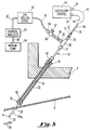
- FIG. 1 the exhaust section 33 of a combustion turbine 1.
- the exhaust section 33 is comprised of an exhaust cylinder 2 which encloses a diffuser formed by approximately cylindrical inner 22 and outer 11 flow liners.
- the exhaust cylinder 2 is bolted at its upstream flange 30 to a turbine cylinder 7 in the turbine section 32 of the combustion turbine.
- a shroud 19 attached to the turbine cylinder 7 encircles the tips of a last row of turbine blades 5.
- Hot gas 29 exhausting from the last row of blades 5 in the turbine section 32 flows through the exhaust section 33. From the exhaust section 33 the hot gas 29 may be either vented to the atmosphere, in a simple cycle power plant, or directed to a heat recovery steam generator, in a combined cycle power plant.
- the inner 22 and outer 11 flow liners form a portion of the flow path 31 for the exhaust gas 29.
- the inner flow liner 22 encloses a bearing housing 9 that contains a bearing 10 that supports a turbine blade rotor 6.
- the bearing housing 9 is supported by struts (not shown) that extend between the bearing housing 9 and the exhaust cylinder 2.
- An exhaust manifold outer cylinder 3 extends downstream from the exhaust cylinder 2 and is bolted at its upstream flange 13 to the exhaust cylinder downstream flange 14.
- a flow guide 12 extends from the exhaust manifold outer cylinder 3 inboard of the flange 13 so as to form a smooth flow path with the outer flow liner 11.
- An exhaust manifold inner cylinder 4 extends downstream from the inner flow liner 22.
- combustion turbines typically have a number of longitudinal guides, such as guide 23, spaced around the annulus of the exhaust cylinder 2. Each guide extends through the exhaust cylinder 2 to a point just above an aperture, e.g. aperture 24, in the outer flow liner 11 of the exhaust diffuser.
- Prior art thermocouple assemblies such as the one shown in Figure 6, are typically inserted into each of the guides to obtain blade path temperature measurements at various points around the diffuser inlet.
- a dual function probe 25 may be inserted into the guide 23 in place of the prior art thermocouple assembly.
- the dual function probe 25 of the present invention provides both a blade path thermocouple function and the ability to extract flow path gases from the exhaust section of the combustion turbine.
- FIG. 2 shows details of the dual function probe 25 of Figure 1 according to a preferred embodiment of the present invention.
- the dual function probe 25 comprises an elongate tubular member 34 having a forward open end 35 and a rearward open end 45.
- the tubular member 34 is made of stainless steel capable of continuous operation in temperatures up to 1300°F.
- the rearward open end 45 of the tubular member 34 is coupled to the inlet 37 of a union tee 36 having first and second outlets 38 and 39, respectively.
- a series of reducers 51, 52 are coupled to the first outlet 38 to effectively reduce the diameter of the first outlet 38 for purposes described hereinafter.
- thermocouple element 40 is centrally disposed within the tubular member 34.
- the inner diameter of the tubular member 34 is sufficiently larger than the outer diameter of the thermocouple element 40 to form an annular space within the tubular member 34.
- the inner diameter of the tubular member 34 may be approximately twice the outer diameter of the thermocouple element 40.
- the thermocouple element 40 has a high integrity, duplex type, grounded measuring junction 41 formed by gathering (not twisting) the four element leads together and inserting a miniature ring around the gathered leads followed by a high temperature stainless steel braze capable of withstanding temperatures approaching 2000°F.
- the measuring junction 41 of the thermocouple element 40 protrudes past the forward open end 35 of the tubular member 34 and is supported by a support plate 43 to maintain the thermocouple element 40 in its centrally disposed position.
- the terminal end 50 of the thermocouple element 40 extends outward through the first outlet 38 of the union tee 36 and through reducers 51 and 52.
- Reducer 52 has a diameter substantially equal to the outer diameter of the terminal end 50 of the thermocouple element 40 so as to form a seal around the terminal end 50.
- the sealing capability of the second reducer 52 is sufficient to withstand differential pressures of up to 150 psia in operating temperatures of at least 1000°F.
- the union tee 36, with its sealed outlet 38, defines a sealed end of the tubular member 34.
- thermocouple element 40 extends into a potted transition assembly 48 wherein the respective element leads of the duplex type measuring junction are spliced, by means of spot welding, to corresponding extension wires 44, 46 that extend outward from the transition assembly 48.
- Male connectors 54, 56 are provided at the ends of the respective extension wires 44, 46 for connecting each element circuit of the duplex type measuring junction to an external control device (not shown).
- the potted transition assembly 48, the extension wires 44, 46 and the male connectors 54, 56 are rated for continuous operation in temperatures up to 500°F.
- An on-off valve 60 is coupled through reducer 58 to the second outlet 39 of the union tee 36.
- the on-off valve 60 comprises a stainless steel ball valve.
- a tubular sleeve 66 may be slidingly fitted over the surface of at least a portion of the tubular member 34 as shown. As explained hereinafter in greater detail, when the lower portion 34a of the tubular member 34 is inserted through the guide 23 in the exhaust section 33 of the combustion turbine 1 (see Figure 1), the sleeve 66 fits tightly within the guide 23 near the aperture 24 in the outer flow liner 11 to provide additional support and vibration damping to the tubular member 34.
- a connector 42 is fitted over the tubular member 34 and is positioned to connect with a mating fixture on the guide 23, as described hereinafter.
- connector 42 may be slid onto the tubular member 34 from the forward end 35, or alternatively, the connector 42 may be slid onto the tubular member 34 from the rearward end 45 prior to coupling the rearward end 45 to the inlet 37 of the union tee 36.
- FIG 3 is a front end view of the dual function probe 25 of Figure 2 taken along line 3--3.
- the support plate 43 is preferably rectangular in shape and is tack welded to the tubular member 34 at points 68.
- An aperture 70 is provided in the support plate 43 through which the measuring junction 41 of the thermocouple element 40 may protrude.
- the support plate 43 supports the protruding measuring junction and thereby maintains the thermocouple element 40 in its centrally disposed position within the tubular member 34.
- the width of the support plate 43 is sized to form ample circular segment shaped openings 72a and 72b with the front end face of the tubular member 34. These are the openings through which exhaust gases will enter the tubular member 34.
- the four element leads 71 of the duplex type measuring junction 41 of the thermocouple element 40 are also shown in Figure 3.
- Figure 4 shows further details of the sleeve 66 of Figure 2.
- the sleeve 66 is made of stainless steel and has an inner diameter D substantially equal to the outer diameter of the tubular member 34 so as to fit tightly over the tubular member 34.
- the insertion end of the sleeve is preferably chamfered at points 90 and 92 to facilitate insertion of the tubular member 34 and sleeve 66 into one of the guides 23 in the exhaust section 33 of the turbine.
- the sleeve 66 may be slid onto the tubular member 34 from the forward end 35, or alternatively, the sleeve 66 may be slid onto the tubular member 34 from the rearward end 45 prior to coupling the rearward end 45 to the inlet 37 of the union tee 36.
- the dual function probe 25 of the present invention is inserted through one of the guides 23 in the exhaust section 33 of the combustion turbine 1.
- the guide 23 extends through the exhaust cylinder 2 to a point just above an aperture 24 in the outer flow liner 11 of the exhaust diffuser.
- the lower portion 34a of the tubular member 34 extends past the end 76 of the guide 23, through the aperture 24, and into the exhaust flow path 31 of the turbine near the turbine blade aft annulus (not shown).
- the connector 42 positioned on the tubular member 34 is then connected to a mating fixture 74 at the insertion end of the guide 23 to secure the probe 25 in the guide 23.
- the connector is positioned on the tubular member 34 and swaged to seal such that when the probe 25 is secured in the guide 23, the measuring junction 41 of the thermocouple element 41 is radially and axially positioned in the flow path 31 of the turbine at a point identical to that of a standard blade path thermocouple assembly measuring junction (e.g., measuring junction 105 of Figure 6). As shown, the sleeve 66 fits tightly within the end 76 of the guide 23 to provide additional support and vibration damping to the tubular member 34.
- thermocouple element 40 The leads of the thermocouple element 40 are connected via extension wires 44, 46 and connectors 54, 56 to a supervisory control device 94, external to the combustion turbine 1, which processes the thermocouple measuring junction data to calculate the blade path temperature within the exhaust cylinder 2 and to control various aspects of the combustion process accordingly.
- the dual function probe 25 of the present invention provides a means for extracting exhaust gases 29 from the flow path 31 of the exhaust cylinder 2.
- Hot gases 29 exhausting from the turbine enter the tubular member 34 of the probe 25 through the circular segment openings 72a, 72b (Fig. 3) in the forward end 35 of the tubular member 34.
- the valve 60 of the probe 25 is open, the exhaust gases are able to escape from the tubular member 34 through the outlet 64 of the valve 60.
- a vacuum pump 88 may be coupled to the outlet 64 via suitable interconnection tubing 78, 82 and 86.
- a chemical analyzer 84 may be coupled between the vacuum pump 88 and valve outlet 64 to analyze the chemical content of the extracted exhaust gases.
- the chemical analyzer 84 may be used to measure the NO x content of the exhaust gases.
- a cooling device 80 may be coupled between the chemical analyzer 84 and the outlet 64 of the valve 60 in order to cool the extracted gases, as needed, to prevent damage to the chemical analyzer 84.
- interconnection tubing 78 is preferably made of a material capable of withstanding temperatures approaching 500°F.
- the interconnection tubing 78 may comprise steel tubing.
- interconnection tubing 82 and 86 may be made of a less temperature resistant material such as, for example, rubber or polyvinylchloride (PVC).
Abstract
A dual function probe (25) for measuring blade path temperature and for extracting exhaust flow gases from a combustion turbine (1) comprises an elongate tubular member (34) having an open end and a sealed end. An elongate thermocouple element (41) is centrally disposed within the tubular member (34) to provide a thermocouple function. At least a portion of the tubular member is adapted for insertion through the exhaust cylinder and diffuser of the combustion turbine (1) and into the flow path of the turbine exhaust gases. An on-off valve (60) is coupled to the tubular member (34) proximate the sealed end thereof to allow exhaust flow gases that enter the open end of the tubular member (34) to be extracted from the tubular member for analysis.
Description
- The present invention relates to a dual function probe for measuring combustion turbine exhaust characteristics. More specifically, the present invention relates to a dual function probe for measuring blade path temperature at the exhaust cylinder diffuser inlet of a combustion turbine and for extracting exhaust flow gases therefrom to facilitate emissions analysis.
- In an axial flow combustion (gas) turbine, the hot gas exhausting from the last row of turbine blades is directed through an exhaust diffuser. The exhaust diffuser is formed by inner and outer flow liners disposed between an exhaust cylinder and a bearing housing. The flow liners serve to create a smooth flow path for the hot gas. They also act as a barrier which prevents the flow of hot gas directly over the exhaust cylinder and bearing housing, thereby preventing excessive temperatures and thermal stresses in these components.
- Efficient operation of a combustion turbine requires constant monitoring of various aspects of the combustion process. One parameter of the combustion process that effects combustion efficiency is the blade path temperature, i.e., the temperature in the exhaust cylinder just aft of the last row of turbine blades. It is desirable, therefore, to periodically sample the blade path temperature in the combustion turbine.
- Blade path temperature is usually measured using one or more thermocouple assemblies that are inserted through corresponding guides in the exhaust cylinder of the turbine such that the measuring junctions of the thermocouple assemblies are positioned within the flow path of the turbine exhaust near the last row of turbine blades. Typically, multiple thermocouple assemblies are inserted at equally spaced points around the annulus of the exhaust cylinder. Each thermocouple provides a blade path temperature reading for a respective one of the turbine's combustors. The measuring junction of each thermocouple is situated downstream from a respective combustor near the turbine blade aft annulus. In this manner, blade path temperature can be monitored for each combustor separately. An example of one such gas turbine engine sensor probe may be found in U.S. Patent 5,185,996.
- With the increasing emphasis on the environment, it is important to ensure that the turbine exhaust does not exceed acceptable emissions levels. Measuring exhaust emissions is therefore an important aspect of combustion turbine operation. In the past, emissions levels have been monitored at the turbine exhaust stack using sensors or probes inserted into the exhaust stack. Because the exhaust stack is situated downstream from the individual turbine combustors, the individual emissions level of each combustor cannot be determined at the exhaust stack.
- It is, therefore, an object of the present invention to provide a means for extracting flow path gases from the exhaust cylinder of a combustion turbine near the turbine blade aft annulus without interrupting blade path temperature readings and without requiring modifications to the exhaust cylinder.
- With this object in view, the present invention resides in a dual function probe characterized by an elongate tubular member having an open end and a sealed end. At least a portion of the tubular member is adapted for insertion through an existing thermocouple assembly guide and into the flow path of the turbine exhaust. An elongate thermocouple element is centrally disposed within the tubular member. An on-off valve is coupled to the tubular member proximate its sealed end for allowing flow gases that enter the open end of the tubular member to exit the tubular member through the valve.
- The invention will become more readily apparent from the following description of the preferred embodiment shown, by way of example only, in the accompanying drawings wherein
- Figure 1 is a partial longitudinal cross-section through the exhaust section of a gas turbine;
- Figure 2 is a side view of a dual function probe according to a preferred embodiment of the present invention;
- Figure 3 is front end view of the dual function probe of Figure 2 taken along line 3-3 of Figure 2;
- Figure 4 is a longitudinal cross-section of the sleeve of Figure 2; and
- Figure 5 is an enlarged view of a portion of Figure 1 illustrating further details of the placement of the dual function probe of the present invention.
- Referring to the drawings, there is shown in Figure 1 the
exhaust section 33 of a combustion turbine 1. Theexhaust section 33 is comprised of anexhaust cylinder 2 which encloses a diffuser formed by approximately cylindrical inner 22 and outer 11 flow liners. Theexhaust cylinder 2 is bolted at its upstream flange 30 to aturbine cylinder 7 in theturbine section 32 of the combustion turbine. Ashroud 19 attached to theturbine cylinder 7 encircles the tips of a last row ofturbine blades 5.Hot gas 29 exhausting from the last row ofblades 5 in theturbine section 32 flows through theexhaust section 33. From theexhaust section 33 thehot gas 29 may be either vented to the atmosphere, in a simple cycle power plant, or directed to a heat recovery steam generator, in a combined cycle power plant. - The inner 22 and outer 11 flow liners form a portion of the
flow path 31 for theexhaust gas 29. Theinner flow liner 22 encloses a bearing housing 9 that contains abearing 10 that supports a turbine blade rotor 6. The bearing housing 9 is supported by struts (not shown) that extend between the bearing housing 9 and theexhaust cylinder 2. An exhaust manifoldouter cylinder 3 extends downstream from theexhaust cylinder 2 and is bolted at itsupstream flange 13 to the exhaust cylinderdownstream flange 14. Aflow guide 12 extends from the exhaust manifoldouter cylinder 3 inboard of theflange 13 so as to form a smooth flow path with the outer flow liner 11. An exhaust manifoldinner cylinder 4 extends downstream from theinner flow liner 22. - As described above, combustion turbines typically have a number of longitudinal guides, such as
guide 23, spaced around the annulus of theexhaust cylinder 2. Each guide extends through theexhaust cylinder 2 to a point just above an aperture,e.g. aperture 24, in the outer flow liner 11 of the exhaust diffuser. Prior art thermocouple assemblies, such as the one shown in Figure 6, are typically inserted into each of the guides to obtain blade path temperature measurements at various points around the diffuser inlet. As shown, however, adual function probe 25 according to the present invention may be inserted into theguide 23 in place of the prior art thermocouple assembly. As will become evident hereinafter, thedual function probe 25 of the present invention provides both a blade path thermocouple function and the ability to extract flow path gases from the exhaust section of the combustion turbine. - Figure 2 shows details of the
dual function probe 25 of Figure 1 according to a preferred embodiment of the present invention. As shown, thedual function probe 25 comprises an elongatetubular member 34 having a forwardopen end 35 and a rearwardopen end 45. Preferably, thetubular member 34 is made of stainless steel capable of continuous operation in temperatures up to 1300°F. The rearwardopen end 45 of thetubular member 34 is coupled to theinlet 37 of aunion tee 36 having first andsecond outlets reducers first outlet 38 to effectively reduce the diameter of thefirst outlet 38 for purposes described hereinafter. - An
elongate thermocouple element 40 is centrally disposed within thetubular member 34. As shown, the inner diameter of thetubular member 34 is sufficiently larger than the outer diameter of thethermocouple element 40 to form an annular space within thetubular member 34. For example, the inner diameter of thetubular member 34 may be approximately twice the outer diameter of thethermocouple element 40. Preferably, thethermocouple element 40 has a high integrity, duplex type, groundedmeasuring junction 41 formed by gathering (not twisting) the four element leads together and inserting a miniature ring around the gathered leads followed by a high temperature stainless steel braze capable of withstanding temperatures approaching 2000°F. Themeasuring junction 41 of thethermocouple element 40 protrudes past the forwardopen end 35 of thetubular member 34 and is supported by asupport plate 43 to maintain thethermocouple element 40 in its centrally disposed position. - The
terminal end 50 of thethermocouple element 40 extends outward through thefirst outlet 38 of theunion tee 36 and throughreducers Reducer 52 has a diameter substantially equal to the outer diameter of theterminal end 50 of thethermocouple element 40 so as to form a seal around theterminal end 50. Preferably, the sealing capability of thesecond reducer 52 is sufficient to withstand differential pressures of up to 150 psia in operating temperatures of at least 1000°F. Theunion tee 36, with its sealedoutlet 38, defines a sealed end of thetubular member 34. - The
terminal end 50 of thethermocouple element 40 extends into apotted transition assembly 48 wherein the respective element leads of the duplex type measuring junction are spliced, by means of spot welding, tocorresponding extension wires transition assembly 48.Male connectors respective extension wires potted transition assembly 48, theextension wires male connectors - An on-off
valve 60 is coupled throughreducer 58 to thesecond outlet 39 of theunion tee 36. Preferably, the on-offvalve 60 comprises a stainless steel ball valve. When thevalve 60 is opened by turning thehandle 62, exhaust flow gases that enter theforward end 35 of the tubular member are able to exit through theoutlet 64 of the valve. When thevalve 60 is closed, no gases can escape. - A
tubular sleeve 66 may be slidingly fitted over the surface of at least a portion of thetubular member 34 as shown. As explained hereinafter in greater detail, when thelower portion 34a of thetubular member 34 is inserted through theguide 23 in theexhaust section 33 of the combustion turbine 1 (see Figure 1), thesleeve 66 fits tightly within theguide 23 near theaperture 24 in the outer flow liner 11 to provide additional support and vibration damping to thetubular member 34. Aconnector 42 is fitted over thetubular member 34 and is positioned to connect with a mating fixture on theguide 23, as described hereinafter. During assembly,connector 42 may be slid onto thetubular member 34 from theforward end 35, or alternatively, theconnector 42 may be slid onto thetubular member 34 from therearward end 45 prior to coupling therearward end 45 to theinlet 37 of theunion tee 36. - Figure 3 is a front end view of the
dual function probe 25 of Figure 2 taken alongline 3--3. As shown, thesupport plate 43 is preferably rectangular in shape and is tack welded to thetubular member 34 at points 68. Anaperture 70 is provided in thesupport plate 43 through which the measuringjunction 41 of thethermocouple element 40 may protrude. Thesupport plate 43 supports the protruding measuring junction and thereby maintains thethermocouple element 40 in its centrally disposed position within thetubular member 34. The width of thesupport plate 43 is sized to form ample circular segment shapedopenings tubular member 34. These are the openings through which exhaust gases will enter thetubular member 34. Also shown in Figure 3 are the four element leads 71 of the duplextype measuring junction 41 of thethermocouple element 40. - Figure 4 shows further details of the
sleeve 66 of Figure 2. Preferably, thesleeve 66 is made of stainless steel and has an inner diameter D substantially equal to the outer diameter of thetubular member 34 so as to fit tightly over thetubular member 34. The insertion end of the sleeve is preferably chamfered atpoints tubular member 34 andsleeve 66 into one of theguides 23 in theexhaust section 33 of the turbine. During assembly of thedual function probe 25, thesleeve 66 may be slid onto thetubular member 34 from theforward end 35, or alternatively, thesleeve 66 may be slid onto thetubular member 34 from therearward end 45 prior to coupling therearward end 45 to theinlet 37 of theunion tee 36. - As best shown in Figure 5, in use, the
dual function probe 25 of the present invention is inserted through one of theguides 23 in theexhaust section 33 of the combustion turbine 1. Theguide 23 extends through theexhaust cylinder 2 to a point just above anaperture 24 in the outer flow liner 11 of the exhaust diffuser. Thelower portion 34a of thetubular member 34 extends past theend 76 of theguide 23, through theaperture 24, and into theexhaust flow path 31 of the turbine near the turbine blade aft annulus (not shown). Theconnector 42 positioned on thetubular member 34 is then connected to amating fixture 74 at the insertion end of theguide 23 to secure theprobe 25 in theguide 23. The connector is positioned on thetubular member 34 and swaged to seal such that when theprobe 25 is secured in theguide 23, the measuringjunction 41 of thethermocouple element 41 is radially and axially positioned in theflow path 31 of the turbine at a point identical to that of a standard blade path thermocouple assembly measuring junction (e.g., measuring junction 105 of Figure 6). As shown, thesleeve 66 fits tightly within theend 76 of theguide 23 to provide additional support and vibration damping to thetubular member 34. - The leads of the
thermocouple element 40 are connected viaextension wires connectors supervisory control device 94, external to the combustion turbine 1, which processes the thermocouple measuring junction data to calculate the blade path temperature within theexhaust cylinder 2 and to control various aspects of the combustion process accordingly. - Simultaneous with the thermocouple function, the
dual function probe 25 of the present invention provides a means for extractingexhaust gases 29 from theflow path 31 of theexhaust cylinder 2.Hot gases 29 exhausting from the turbine enter thetubular member 34 of theprobe 25 through thecircular segment openings forward end 35 of thetubular member 34. When thevalve 60 of theprobe 25 is open, the exhaust gases are able to escape from thetubular member 34 through theoutlet 64 of thevalve 60. To facilitate extraction, avacuum pump 88 may be coupled to theoutlet 64 viasuitable interconnection tubing - A
chemical analyzer 84 may be coupled between thevacuum pump 88 andvalve outlet 64 to analyze the chemical content of the extracted exhaust gases. In particular, thechemical analyzer 84 may be used to measure the NOx content of the exhaust gases. A coolingdevice 80 may be coupled between thechemical analyzer 84 and theoutlet 64 of thevalve 60 in order to cool the extracted gases, as needed, to prevent damage to thechemical analyzer 84. Because of the high temperature of the extracted gases,interconnection tubing 78 is preferably made of a material capable of withstanding temperatures approaching 500°F. For example, theinterconnection tubing 78 may comprise steel tubing. When thecooling device 80 is employed, however,interconnection tubing
Claims (9)
- A dual function probe (25) for measuring blade path temperature and for extracting exhaust flow gases from a combustion turbine (1), characterized by:
an elongate tubular member (34) having an open end (35) and a sealed end, at least a portion of said tubular member proximate said open end thereof being adapted for insertion into the exhaust gas flow path (31) of the combustion turbine;
an elongate thermocouple element (40), having a measuring junction (41), and a terminal end (50), centrally disposed within said tubular member; and
an on-off valve (60) coupled to said tubular member (34) proximate said sealed end thereof for allowing exhaust flow gases (29) that enter said open end of said tubular member (34) to exit said tubular member (34) through said valve (60). - A dual function probe (25) as recited in claim 1 wherein said measuring junction (41) of said thermocouple element (40) at least partially protrudes from the open end (35) of said tubular member (34), and wherein said dual function probe (25) is further characterized by a support plate (43) coupled to said open end of said tubular member (34) and having an aperture (70) through which said measuring junction (41) of said thermocouple element (40) protrudes to support said thermocouple element (40) in its centrally disposed position within said tubular member.
- A dual function probe (25) as recited in claim 1 wherein said terminal end (50) of said thermocouple element (40) extends outward through said sealed end of said tubular member (34) to connect with an external control device (94).
- A dual function probe (25) as recited in claim 1 wherein said measuring junction (41) of said thermocouple element (40) comprises a duplex type measuring junction.
- A dual function probe (25) as recited in claim 1 further characterized by a sleeve (66) slidably fitted over the outer surface of at least a portion of said tubular member (34).
- A dual function probe (25) as recited in claim 1 further characterized by a vacuum pump (88) coupled to said on-off valve (60) to facilitate extraction of exhaust flow gases from said tubular member (34) when said on-off valve (60) is open.
- A dual function probe (25) as recited in claim 1 further characterized by a chemical analyzer (84) coupled to said on-off valve (60) for analyzing the exhaust flow gases extracted through said valve when said valve is open.
- A dual function probe as recited in claim 7 further characterized by a cooling device (80) coupled between said valve (60) and said chemical analyzer (84) to cool the exhaust flow gases to prevent damage to said analyzer.
- A dual function probe as recited in claim 1 wherein said valve (60) is coupled to said tubular member (34) with a union tee (36).
Applications Claiming Priority (2)
| Application Number | Priority Date | Filing Date | Title |
|---|---|---|---|
| US08/141,755 US5404760A (en) | 1993-10-27 | 1993-10-27 | Blade path thermocouple and exhaust gas extraction probe for combustion turbines |
| US141755 | 1993-10-27 |
Publications (1)
| Publication Number | Publication Date |
|---|---|
| EP0651138A1 true EP0651138A1 (en) | 1995-05-03 |
Family
ID=22497086
Family Applications (1)
| Application Number | Title | Priority Date | Filing Date |
|---|---|---|---|
| EP94307824A Withdrawn EP0651138A1 (en) | 1993-10-27 | 1994-10-25 | Blade path thermocouple and exhaust gas extraction probe for combustion turbines |
Country Status (8)
| Country | Link |
|---|---|
| US (1) | US5404760A (en) |
| EP (1) | EP0651138A1 (en) |
| JP (1) | JPH07190903A (en) |
| KR (1) | KR950011820A (en) |
| CN (1) | CN1107937A (en) |
| AU (1) | AU7575494A (en) |
| CA (1) | CA2134421A1 (en) |
| TW (1) | TW247341B (en) |
Cited By (3)
| Publication number | Priority date | Publication date | Assignee | Title |
|---|---|---|---|---|
| DE102009009839A1 (en) * | 2009-01-22 | 2010-07-29 | Tesona Gmbh & Co. Kg | Multi-functional sensor arrangement for use in high temperature region of internal-combustion engine for turbocharger, has group of passages establishing direct pressure-side connection between measuring area and sensor |
| US9791351B2 (en) | 2015-02-06 | 2017-10-17 | General Electric Company | Gas turbine combustion profile monitoring |
| EP2778638B1 (en) | 2007-06-22 | 2017-11-29 | Watlow Electric Manufacturing Company | Temperature sensor assembly |
Families Citing this family (28)
| Publication number | Priority date | Publication date | Assignee | Title |
|---|---|---|---|---|
| DE4421807A1 (en) * | 1994-06-22 | 1996-01-04 | Abb Management Ag | Emission probe for extracting exhaust gas from the combustion chamber of a gas turbine and method for producing and using the same |
| DE19523599A1 (en) * | 1995-06-30 | 1997-01-02 | Ruhrgas Ag | Mass flow rate determination of emitted component in engine exhaust gases |
| US6561046B1 (en) * | 2000-10-12 | 2003-05-13 | Mclane Research Laboratories | Sampling apparatus for collecting samples from underwater hydrothermal vents and the marine or limnological water column |
| US6843061B2 (en) * | 2002-02-15 | 2005-01-18 | Siemens Westinghouse Power Corporation | Gas turbine with flexible combustion sensor connection |
| US6857776B2 (en) | 2002-12-12 | 2005-02-22 | Ametek, Inc. | Connectorized high-temperature thermocouple |
| US20060041368A1 (en) * | 2004-08-18 | 2006-02-23 | General Electric Company | Systems, Methods and Computer Program Products for Remote Monitoring of Turbine Combustion Dynamics |
| US7581382B2 (en) | 2005-04-28 | 2009-09-01 | United Technologies Corporation | Gas turbine engine air valve assembly |
| KR100868525B1 (en) * | 2007-08-13 | 2008-11-12 | 한국중부발전(주) | Multi thermocouple for gas turbine exhaust gas |
| US7553079B1 (en) * | 2008-01-17 | 2009-06-30 | Gm Global Technology Operations, Inc. | Temperature sensor assembly |
| US8925328B2 (en) * | 2009-10-26 | 2015-01-06 | Siemens Energy, Inc. | Gas turbine starting process |
| US8312780B2 (en) | 2010-06-25 | 2012-11-20 | Mettler-Toledo Ag | Sampling device and method |
| US8365617B2 (en) | 2010-06-25 | 2013-02-05 | Mettler-Toledo Ag | Sampling device |
| US20120023967A1 (en) * | 2010-07-30 | 2012-02-02 | Dede Brian C | Auxiliary power unit with hot section fire enclosure arrangement |
| US8667659B2 (en) * | 2011-01-19 | 2014-03-11 | Mettler-Toledo Ag | System and method for coupling an extendable element to an actuator |
| US9086303B2 (en) | 2012-04-27 | 2015-07-21 | Rosemount Inc. | Vibration damper for sensor housing |
| DE102012217535A1 (en) * | 2012-09-27 | 2014-03-27 | Siemens Aktiengesellschaft | Gas turbine with a heat flow sensor |
| US9297720B2 (en) | 2012-12-21 | 2016-03-29 | United Technologies Corporation | Gas turbine engine vane embedded beam interrupt optical tip-timing probe system |
| CN103323293A (en) * | 2013-06-26 | 2013-09-25 | 国家电网公司 | Sealed integrated smoke collection test device |
| US9790834B2 (en) | 2014-03-20 | 2017-10-17 | General Electric Company | Method of monitoring for combustion anomalies in a gas turbomachine and a gas turbomachine including a combustion anomaly detection system |
| CN105588652A (en) * | 2015-12-15 | 2016-05-18 | 中国燃气涡轮研究院 | Air spraying-based turbine blade temperature measurement method |
| CN105675158A (en) * | 2016-01-06 | 2016-06-15 | 南京航空航天大学 | Device and method for simultaneously measuring gas turbine combustion chamber outlet temperature and combustion product concentration |
| WO2018120111A1 (en) * | 2016-12-30 | 2018-07-05 | Rosemount Inc. | Adjustable spring loaded adapter for temperature sensor |
| CN106989846B (en) * | 2017-05-22 | 2019-05-17 | 北京航空航天大学 | A kind of device measuring high temperature gas flow total temperature |
| CN113566993A (en) * | 2020-04-28 | 2021-10-29 | 中国航发商用航空发动机有限责任公司 | Engine temperature measuring device and heat insulation lining thereof |
| US11473480B2 (en) * | 2021-02-18 | 2022-10-18 | Pratt & Whitney Canada Corp. | Instrumented turbine exhaust duct |
| US11339679B1 (en) * | 2021-03-23 | 2022-05-24 | Pratt & Whitney Canada Corp. | Turbine probe heat shielding |
| US11428122B1 (en) * | 2021-03-23 | 2022-08-30 | Pratt & Whitney Canada Corp. | Thermal protection for a gas turbine engine probe |
| US11859503B1 (en) | 2022-06-30 | 2024-01-02 | Pratt & Whitney Canada Corp. | Probe heat shielding |
Citations (3)
| Publication number | Priority date | Publication date | Assignee | Title |
|---|---|---|---|---|
| DE2163045A1 (en) * | 1971-12-18 | 1973-06-28 | Daimler Benz Ag | COMBINATION PROBE |
| GB2076535A (en) * | 1980-04-28 | 1981-12-02 | Gen Electric | Removable probe-carrying sealing plug for spaced apart wall structure |
| EP0477133A1 (en) * | 1990-09-10 | 1992-03-25 | Linde Aktiengesellschaft | Low temperature measuring apparatus |
Family Cites Families (3)
| Publication number | Priority date | Publication date | Assignee | Title |
|---|---|---|---|---|
| US4355539A (en) * | 1980-12-30 | 1982-10-26 | Mobil Oil Corporation | Fluid sampling probe |
| NL8103306A (en) * | 1981-07-10 | 1983-02-01 | Estel Hoogovens Bv | AUXILIARY PLAN FOR MEASURING AND / OR SAMPLING IN A METALLURGIC OVEN AND METHOD FOR USING THIS AUXILIARY. |
| US5185996A (en) * | 1990-12-21 | 1993-02-16 | Allied-Signal Inc. | Gas turbine engine sensor probe |
-
1993
- 1993-10-27 US US08/141,755 patent/US5404760A/en not_active Expired - Fee Related
-
1994
- 1994-10-06 TW TW083109272A patent/TW247341B/zh active
- 1994-10-12 AU AU75754/94A patent/AU7575494A/en not_active Abandoned
- 1994-10-25 EP EP94307824A patent/EP0651138A1/en not_active Withdrawn
- 1994-10-26 CA CA002134421A patent/CA2134421A1/en not_active Abandoned
- 1994-10-26 KR KR1019940027386A patent/KR950011820A/en not_active Application Discontinuation
- 1994-10-27 JP JP6289136A patent/JPH07190903A/en not_active Withdrawn
- 1994-10-27 CN CN94117606A patent/CN1107937A/en active Pending
Patent Citations (3)
| Publication number | Priority date | Publication date | Assignee | Title |
|---|---|---|---|---|
| DE2163045A1 (en) * | 1971-12-18 | 1973-06-28 | Daimler Benz Ag | COMBINATION PROBE |
| GB2076535A (en) * | 1980-04-28 | 1981-12-02 | Gen Electric | Removable probe-carrying sealing plug for spaced apart wall structure |
| EP0477133A1 (en) * | 1990-09-10 | 1992-03-25 | Linde Aktiengesellschaft | Low temperature measuring apparatus |
Cited By (3)
| Publication number | Priority date | Publication date | Assignee | Title |
|---|---|---|---|---|
| EP2778638B1 (en) | 2007-06-22 | 2017-11-29 | Watlow Electric Manufacturing Company | Temperature sensor assembly |
| DE102009009839A1 (en) * | 2009-01-22 | 2010-07-29 | Tesona Gmbh & Co. Kg | Multi-functional sensor arrangement for use in high temperature region of internal-combustion engine for turbocharger, has group of passages establishing direct pressure-side connection between measuring area and sensor |
| US9791351B2 (en) | 2015-02-06 | 2017-10-17 | General Electric Company | Gas turbine combustion profile monitoring |
Also Published As
| Publication number | Publication date |
|---|---|
| JPH07190903A (en) | 1995-07-28 |
| KR950011820A (en) | 1995-05-16 |
| US5404760A (en) | 1995-04-11 |
| CA2134421A1 (en) | 1995-04-28 |
| TW247341B (en) | 1995-05-11 |
| AU7575494A (en) | 1995-05-18 |
| CN1107937A (en) | 1995-09-06 |
Similar Documents
| Publication | Publication Date | Title |
|---|---|---|
| EP0651138A1 (en) | Blade path thermocouple and exhaust gas extraction probe for combustion turbines | |
| US3348414A (en) | Gas turbine temperature measuring apparatus | |
| US9880059B2 (en) | Gas turbine exhaust diffuser mounted blade path thermocouple probe | |
| US8033719B2 (en) | Gas turbine with protective sheath for a probe and method for protecting an instrument lead which is laid in a protective sheath | |
| EP2610599A2 (en) | Temperature sensing device and method of assembling the same | |
| US20060140754A1 (en) | Gas turbine | |
| US4503668A (en) | Strutless diffuser for gas turbine engine | |
| WO1992011445A1 (en) | Gas turbine engine sensor probe | |
| CN104685158B (en) | There is gas-turbine unit preswirl device and the manufacture method thereof of inclined hole | |
| CA2558897A1 (en) | Redundant fuel manifold sealing arrangement | |
| CN109424981B (en) | Transition duct for a gas turbine can-combustor and gas turbine comprising such a transition duct | |
| US9207128B2 (en) | Dynamic fiber temperature sensing package and method of assembling the same | |
| US4244221A (en) | Removable instrumentation probe | |
| JP2012112378A (en) | Sensor assembly for use with turbomachine and methods for assembling the same | |
| US20170342910A1 (en) | Attachment system for a gas turbine engine | |
| KR101146056B1 (en) | Cooled probe for sampling exhaust gas | |
| EP3473817A1 (en) | Inlet performance measurement system for gas turbine engine | |
| US4948264A (en) | Apparatus for indirectly determining the temperature of a fluid | |
| US9698579B2 (en) | Method for routing wire bundles from a rotor shaft of a turbomachine | |
| CA1199815A (en) | Turbine disc cavity temperature sensing arrangement | |
| US11243119B2 (en) | Protective sleeve for a component of a turbine engine and method of installing the same | |
| US11473480B2 (en) | Instrumented turbine exhaust duct | |
| US11307100B2 (en) | Gas turbine exhaust thermocouple assembly | |
| US20200041353A1 (en) | Exhaust gas temperature sensor | |
| CA3085181A1 (en) | Method and system for measuring temperature in a gas turbine engine |
Legal Events
| Date | Code | Title | Description |
|---|---|---|---|
| PUAI | Public reference made under article 153(3) epc to a published international application that has entered the european phase |
Free format text: ORIGINAL CODE: 0009012 |
|
| AK | Designated contracting states |
Kind code of ref document: A1 Designated state(s): BE CH DE ES FR GB IT LI NL SE |
|
| 17P | Request for examination filed |
Effective date: 19951103 |
|
| 17Q | First examination report despatched |
Effective date: 19960709 |
|
| STAA | Information on the status of an ep patent application or granted ep patent |
Free format text: STATUS: THE APPLICATION IS DEEMED TO BE WITHDRAWN |
|
| 18D | Application deemed to be withdrawn |
Effective date: 19961120 |