EP0650555B1 - Carburetor assembly for an internal combustion gas engine - Google Patents
Carburetor assembly for an internal combustion gas engine Download PDFInfo
- Publication number
- EP0650555B1 EP0650555B1 EP93916760A EP93916760A EP0650555B1 EP 0650555 B1 EP0650555 B1 EP 0650555B1 EP 93916760 A EP93916760 A EP 93916760A EP 93916760 A EP93916760 A EP 93916760A EP 0650555 B1 EP0650555 B1 EP 0650555B1
- Authority
- EP
- European Patent Office
- Prior art keywords
- throttle
- shaft
- carburetor
- passage
- throttle body
- Prior art date
- Legal status (The legal status is an assumption and is not a legal conclusion. Google has not performed a legal analysis and makes no representation as to the accuracy of the status listed.)
- Expired - Lifetime
Links
- 239000000567 combustion gas Substances 0.000 title abstract description 4
- 239000000446 fuel Substances 0.000 claims abstract description 28
- 239000000203 mixture Substances 0.000 claims abstract description 19
- 239000002826 coolant Substances 0.000 claims description 6
- 239000007788 liquid Substances 0.000 claims description 4
- 230000004044 response Effects 0.000 claims description 4
- 230000000694 effects Effects 0.000 claims description 2
- 238000002955 isolation Methods 0.000 claims description 2
- VNWKTOKETHGBQD-UHFFFAOYSA-N methane Chemical compound C VNWKTOKETHGBQD-UHFFFAOYSA-N 0.000 abstract description 14
- 238000002485 combustion reaction Methods 0.000 abstract description 10
- 239000007789 gas Substances 0.000 abstract description 7
- 239000003345 natural gas Substances 0.000 abstract description 7
- 238000007789 sealing Methods 0.000 abstract 1
- 230000007246 mechanism Effects 0.000 description 4
- 230000008859 change Effects 0.000 description 3
- 238000000889 atomisation Methods 0.000 description 2
- 230000027455 binding Effects 0.000 description 2
- 238000010586 diagram Methods 0.000 description 2
- 230000001052 transient effect Effects 0.000 description 2
- 241000238876 Acari Species 0.000 description 1
- 230000000712 assembly Effects 0.000 description 1
- 238000000429 assembly Methods 0.000 description 1
- 238000004891 communication Methods 0.000 description 1
- 238000010276 construction Methods 0.000 description 1
- 230000008878 coupling Effects 0.000 description 1
- 238000010168 coupling process Methods 0.000 description 1
- 238000005859 coupling reaction Methods 0.000 description 1
- 230000001186 cumulative effect Effects 0.000 description 1
- 230000000994 depressogenic effect Effects 0.000 description 1
- 239000012530 fluid Substances 0.000 description 1
- 230000001095 motoneuron effect Effects 0.000 description 1
- 239000010705 motor oil Substances 0.000 description 1
- 239000003921 oil Substances 0.000 description 1
- 238000011144 upstream manufacturing Methods 0.000 description 1
- 210000000707 wrist Anatomy 0.000 description 1
Images




Classifications
-
- F—MECHANICAL ENGINEERING; LIGHTING; HEATING; WEAPONS; BLASTING
- F02—COMBUSTION ENGINES; HOT-GAS OR COMBUSTION-PRODUCT ENGINE PLANTS
- F02D—CONTROLLING COMBUSTION ENGINES
- F02D19/00—Controlling engines characterised by their use of non-liquid fuels, pluralities of fuels, or non-fuel substances added to the combustible mixtures
- F02D19/02—Controlling engines characterised by their use of non-liquid fuels, pluralities of fuels, or non-fuel substances added to the combustible mixtures peculiar to engines working with gaseous fuels
- F02D19/021—Control of components of the fuel supply system
- F02D19/023—Control of components of the fuel supply system to adjust the fuel mass or volume flow
-
- F—MECHANICAL ENGINEERING; LIGHTING; HEATING; WEAPONS; BLASTING
- F02—COMBUSTION ENGINES; HOT-GAS OR COMBUSTION-PRODUCT ENGINE PLANTS
- F02D—CONTROLLING COMBUSTION ENGINES
- F02D11/00—Arrangements for, or adaptations to, non-automatic engine control initiation means, e.g. operator initiated
- F02D11/06—Arrangements for, or adaptations to, non-automatic engine control initiation means, e.g. operator initiated characterised by non-mechanical control linkages, e.g. fluid control linkages or by control linkages with power drive or assistance
- F02D11/10—Arrangements for, or adaptations to, non-automatic engine control initiation means, e.g. operator initiated characterised by non-mechanical control linkages, e.g. fluid control linkages or by control linkages with power drive or assistance of the electric type
-
- F—MECHANICAL ENGINEERING; LIGHTING; HEATING; WEAPONS; BLASTING
- F02—COMBUSTION ENGINES; HOT-GAS OR COMBUSTION-PRODUCT ENGINE PLANTS
- F02D—CONTROLLING COMBUSTION ENGINES
- F02D9/00—Controlling engines by throttling air or fuel-and-air induction conduits or exhaust conduits
- F02D9/08—Throttle valves specially adapted therefor; Arrangements of such valves in conduits
- F02D9/10—Throttle valves specially adapted therefor; Arrangements of such valves in conduits having pivotally-mounted flaps
-
- F—MECHANICAL ENGINEERING; LIGHTING; HEATING; WEAPONS; BLASTING
- F02—COMBUSTION ENGINES; HOT-GAS OR COMBUSTION-PRODUCT ENGINE PLANTS
- F02M—SUPPLYING COMBUSTION ENGINES IN GENERAL WITH COMBUSTIBLE MIXTURES OR CONSTITUENTS THEREOF
- F02M21/00—Apparatus for supplying engines with non-liquid fuels, e.g. gaseous fuels stored in liquid form
- F02M21/02—Apparatus for supplying engines with non-liquid fuels, e.g. gaseous fuels stored in liquid form for gaseous fuels
- F02M21/0218—Details on the gaseous fuel supply system, e.g. tanks, valves, pipes, pumps, rails, injectors or mixers
- F02M21/023—Valves; Pressure or flow regulators in the fuel supply or return system
- F02M21/0239—Pressure or flow regulators therefor
-
- F—MECHANICAL ENGINEERING; LIGHTING; HEATING; WEAPONS; BLASTING
- F02—COMBUSTION ENGINES; HOT-GAS OR COMBUSTION-PRODUCT ENGINE PLANTS
- F02M—SUPPLYING COMBUSTION ENGINES IN GENERAL WITH COMBUSTIBLE MIXTURES OR CONSTITUENTS THEREOF
- F02M21/00—Apparatus for supplying engines with non-liquid fuels, e.g. gaseous fuels stored in liquid form
- F02M21/02—Apparatus for supplying engines with non-liquid fuels, e.g. gaseous fuels stored in liquid form for gaseous fuels
- F02M21/04—Gas-air mixing apparatus
- F02M21/047—Venturi mixer
-
- F—MECHANICAL ENGINEERING; LIGHTING; HEATING; WEAPONS; BLASTING
- F02—COMBUSTION ENGINES; HOT-GAS OR COMBUSTION-PRODUCT ENGINE PLANTS
- F02B—INTERNAL-COMBUSTION PISTON ENGINES; COMBUSTION ENGINES IN GENERAL
- F02B43/00—Engines characterised by operating on gaseous fuels; Plants including such engines
-
- F—MECHANICAL ENGINEERING; LIGHTING; HEATING; WEAPONS; BLASTING
- F02—COMBUSTION ENGINES; HOT-GAS OR COMBUSTION-PRODUCT ENGINE PLANTS
- F02D—CONTROLLING COMBUSTION ENGINES
- F02D11/00—Arrangements for, or adaptations to, non-automatic engine control initiation means, e.g. operator initiated
- F02D11/06—Arrangements for, or adaptations to, non-automatic engine control initiation means, e.g. operator initiated characterised by non-mechanical control linkages, e.g. fluid control linkages or by control linkages with power drive or assistance
- F02D11/10—Arrangements for, or adaptations to, non-automatic engine control initiation means, e.g. operator initiated characterised by non-mechanical control linkages, e.g. fluid control linkages or by control linkages with power drive or assistance of the electric type
- F02D2011/101—Arrangements for, or adaptations to, non-automatic engine control initiation means, e.g. operator initiated characterised by non-mechanical control linkages, e.g. fluid control linkages or by control linkages with power drive or assistance of the electric type characterised by the means for actuating the throttles
- F02D2011/102—Arrangements for, or adaptations to, non-automatic engine control initiation means, e.g. operator initiated characterised by non-mechanical control linkages, e.g. fluid control linkages or by control linkages with power drive or assistance of the electric type characterised by the means for actuating the throttles at least one throttle being moved only by an electric actuator
-
- F—MECHANICAL ENGINEERING; LIGHTING; HEATING; WEAPONS; BLASTING
- F02—COMBUSTION ENGINES; HOT-GAS OR COMBUSTION-PRODUCT ENGINE PLANTS
- F02D—CONTROLLING COMBUSTION ENGINES
- F02D9/00—Controlling engines by throttling air or fuel-and-air induction conduits or exhaust conduits
- F02D9/08—Throttle valves specially adapted therefor; Arrangements of such valves in conduits
- F02D9/10—Throttle valves specially adapted therefor; Arrangements of such valves in conduits having pivotally-mounted flaps
- F02D9/107—Manufacturing or mounting details
-
- Y—GENERAL TAGGING OF NEW TECHNOLOGICAL DEVELOPMENTS; GENERAL TAGGING OF CROSS-SECTIONAL TECHNOLOGIES SPANNING OVER SEVERAL SECTIONS OF THE IPC; TECHNICAL SUBJECTS COVERED BY FORMER USPC CROSS-REFERENCE ART COLLECTIONS [XRACs] AND DIGESTS
- Y02—TECHNOLOGIES OR APPLICATIONS FOR MITIGATION OR ADAPTATION AGAINST CLIMATE CHANGE
- Y02T—CLIMATE CHANGE MITIGATION TECHNOLOGIES RELATED TO TRANSPORTATION
- Y02T10/00—Road transport of goods or passengers
- Y02T10/10—Internal combustion engine [ICE] based vehicles
- Y02T10/30—Use of alternative fuels, e.g. biofuels
Definitions
- Our invention relates generally to internal combustion engines using natural gas as a fuel and to improvements in a carburetor for developing a combustible mixture of natural gas and air for an internal combustion gas engine.
- An electronic control system in the system disclosed in the '592 patent is adapted to detect vehicle wheel slip if the vehicle is running on a low friction surface.
- an appropriate signal is developed by the microprocessor to adjust the stepper motor to compensate for the slip and to reduce the throttle setting, thus reducing engine torque in order to reduce the degree of wheel slip in a transient fashion.
- the stepper motor will respond to a change in the magnitude of the slip signal by adjusting the throttle blade to the original position determined by the accelerator pedal position selected by the operator.
- Our invention comprises improvements in gas carburetors adapted especially for use in a venturi-type carburetor throat wherein the venturi throat develops a negative pressure as air is induced through the air intake valve during operation of an internal combustion engine. This creates a controlled flow of natural gas through a gas flow mixture valve.
- the carburetor comprises a throttle body, an air inlet passage in said throttle body adapted to communicate with an air/fuel mixture inlet flow conduit;
- a throttle plate is located on the downstream side of the venturi section of the carburetor.
- the throttle plate is carried by a throttle shaft.
- the throttle plate is connected to the shaft by a mechanical connection which may accommodate a controlled amount of free play of the throttle plate with respect to the shaft to avoid any interference problems that may be caused by misalignment of the shaft relative to the carburetor body.
- This construction makes it possible to reduce clearances between the throttle plate and the carburetor body without causing interference in throttle plate movement. Leakage of air into the air/fuel mixture, furthermore, is prevented by the absence of a throttle shaft with shaft bearings in the air flow path.
- a stepper motor mechanism is secured to the carburetor throttle body.
- the armature of the stepper motor is connected to the throttle shaft by a direct connection in the form of a coupling sleeve without the necessity for using a separate bearing for either the armature shaft or the throttle shaft.
- this preferred design eliminates the need for providing a running seal on either the stepper motor shaft or the throttle shaft. In this way, the throttle setting can respond accurately to input signals delivered to the stepper motor. Throttle friction, which could cause loss of control stability, is avoided. No compensation for shaft seal friction is required and no compensation for bearing friction is required because neither shaft seals nor shaft bearings are used.
- Our preferred carburetor assembly also includes an electronically-controlled mixture enrichment valve situated in the carburetor assembly at a location adjacent the venturi element in parallel disposition with respect to the gas flow path .mb0 extending to the venturi section.
- the enrichment valve responds to engine oil temperature to provide a parallel flow path for the fuel that enters the venturi section when the temperature is low. This permits the fuel mixture to approach a stoichiometric condition to facilitate starting and to reduce the energy requirements for the ignition device in the engine cylinder head.
- the temperature-responsive enrichment valve will close the bypass flow path, thereby establishing a desired lean mixture for normal engine operation.
- the enrichment valve may respond to coolant temperature as well as oil temperature.
- Figure 1 is a partial cross-sectional view of a carburetor assembly incorporating the improvements of our invention.
- Figure 1A is a side elevation view of the assembly shown in Figures 1 and 2.
- Figure 2 is a cross-sectional view taken along the plane of section line 2-2 of Figure 1.
- Figure 3 is a view of typical internal combustion engine cylinder head assembly showing an intake valve and an exhaust valve.
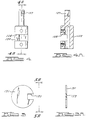
- FIG 4 is a detailed view of the throttle shaft for the throttle blade shown in the assembly views of Figures 1 and 2.
- Figure 4A is a cross-sectional view of the assembly of Figure 4.
- FIG 5 is a detail plan view of a throttle blade for the carburetor assembly of Figures 1 and 2.
- Figure 5A is an end view of the throttle blade as seen from the plane of section line 5A-5A of Figure 5.
- FIG 6 is a schematic circuit drawing of the throttle closed-loop control for the carburetor of Figures 1 and 2.
- Figure 7 is a block diagram of a secondary control loop within the closed-loop control of Figure 6 for incrementing or decrementing the throttle position after a throttle position command is developed in the Figure 6 sequence.
- FIG 8 is a flow chart showing the throttle control logic carried out by the electronic processor for the throttle control as the functions of the control of Figure 7 are executed.
- FIG. 3 shows in cross-section a crankcase and cylinder housing and a cylinder head for an internal combustion engine.
- the crankcase and cylinder housing is shown at 10.
- a piston 12 is positioned in cylinder 14 formed in the housing 10. It is connected by a piston rod 16 to a crankshaft (not shown).
- Piston rod 16 is connected to the piston by means of a wrist pin 18.
- a cylinder head 20 is bolted to the upper face 22 of the housing 10 .
- An air/fuel mixture intake valve 24 and a combustion gas exhaust valve 26 are positioned in the cylinder head above the piston.
- Valve 24 slides in a valve sleeve 28.
- a corresponding valve sleeve 30 is provided for the exhaust valve 26.
- Liquid coolant passages 32 are formed in the cylinder head, and liquid coolant passages 34 are formed in the housing 10.
- Valve spring 36 normally seats valve 24 against valve seat 38.
- Valve spring 40 normally seats the valve 26 against valve seat 42.
- the space above the piston and below the valves 24 and 26 is a combustion chamber which receives a combustible air/fuel mixture through the intake valve 24.
- An intake flow passage 44 is closed by the valve 24 when the valve 24 assumes the position shown in Figure 3.
- Passage 44 is formed in the cylinder head 20 and extends transversely with respect to the axis of the valve 24 as seen in Figure 3 at 44'.
- a carburetor assembly is shown in Figure 2. It includes a throttle body 46 having a mounting face 48 which can be bolted to the side of the cylinder head 20 so that passage 44' will communicate with fuel mixture flow passage 50.
- the throttle body is provided with a cylindrical opening 52 in alignment with the passage 50. It receives a venturi element 54 as shown in Figure 2.
- the venturi element 54 comprises a flow inlet section 56, a throat section 58 and a diffuser section 60.
- the diameter of the diffuser section progressively increases until it matches the diameter of the flow passage 50.
- An inlet air flow passage (not shown) can be received over the outside diameter of the throttle body 46.
- An air filter can be included in the air intake conduit.
- Gas fuel supply ports 62 are provided at the throat 58 of the venturi section 54. Surrounding the venturi section 54 is an annular space 64 which communicates with the ports 62.
- the throttle body 46 includes an enlarged section 66 in which is formed a gas flow passage 68 extending in a direction transverse with respect to the axis 70 of the passage 50.
- a fuel metering orifice plate 72 located in the fuel flow passage 68 contains an orifice 74 which registers with a needle valve element 76 carried by valve stem 78, which is threaded in a threaded opening 80 formed in the throttle body 46.
- the head 82 of the stem 78 can be adjusted to control the effective flow area of the orifice 74.
- Valve spring 84 maintains a proper adjustment of the valve stem 78 once it is set at a calibrated position.
- a natural gas supply conduit (not shown) can be threaded at 86 in the portion 88 of the flow passage 68 upstream from the orifice 74.
- a fuel enrichment valve assembly 90 includes a solenoid body 92 having a threaded extension 94 that is received in a threaded opening 96 in the throttle body 46.
- a bypass port 98 communicates with the passage portion 88.
- a valve element 100 carried at the end of the armature of solenoid valve 90 is adapted to normally close the port 98 as indicated in Figure 1.
- Valve element 100 is situated in a valve chamber 102, and a bypass passage 104 communicates with the chamber and with flow passage 68 on the downstream side of the orifice 74. Thus, when the solenoid is energized, valve element 100 opens passage 98 to establish communication across the orifice 74. This provides a parallel gas flow passage to the engine intake valve and enriches the mixture for starting the engine when the coolant temperature is low.
- An electric stepper motor 106 is bolted to the throttle body 46. It includes a housing having an extension 108 received in opening 110 in the throttle body 46. A fluid seal, preferably an O-ring type seal, is situated between the extension 108 and the surrounding wall of the opening 110 as shown at 112.
- the stepper motor comprises an armature shaft 114 which is received within a throttle blade shaft assembly 116, as best seen in Figure 2.
- a throttle shaft 118 forms a part of the throttle shaft assembly 116 and extends through opening 120 in the throttle body so that the shaft 118 can extend within the passage 50.
- Shaft assembly 116 includes also a sleeve 122 received over the armature shaft 114. It is held in place by set screws 124 and 126 received in threaded openings formed in the sleeve 122.
- the end of the shaft assembly portion 118 is slotted as shown in Figures 4 and 4A.
- the slot is identified by reference numeral 127.
- Throttle plate 131 as seen in Figures 5 and 5A, is circular and is provided with a recess 133.
- the recess 133 registers with the slot 127, thereby establishing a loose, lost-motion connection between the shaft 118 and the throttle plate 130.
- the diameter of the throttle plate 131 is slightly less than the diameter of the passage 50 to avoid interference.
- the sleeve portion 122 is provided with a transverse slot 128 as seen in Figures 4 and 4A.
- a wall 130 of the slot 128 is adapted to engage a stop in the form of a set screw 132 as seen in Figure 1A.
- the set screw 132 is threadably received in an opening formed in the throttle body 46. Its inner end 134 is adapted to engage wall 130 of the slot 128 when the throttle blade assumes a closed position.
- the contact between the stop and the contact wall 130 is normal to the direction of motion so no friction resistance or binding action is developed when the throttle blade is adjusted to its closed position.
- the outer end of the adjustable set screw 132 extends outwardly from the throttle body 46 and may be adjusted by a hand tool.
- a lock nut 136 threaded on the adjustment screw 132 holds the screw 132 in place after adjustment is completed.
- the engine throttle control scheme is illustrated in the block diagram of Figure 6. It includes a digital proportional-integral-derivative control algorithm in order to regulate the speed of the engine.
- the engine speed set point which is established by the engine controller, is determined at 138.
- the actual engine speed is measured at 140. This is done by using a camshaft speed sensor for the engine of Figure 3.
- the speed error is determined at the summing point 142 shown in Figure 6.
- the PID-controller is inserted into the control loop of Figure 6 as part of the forward gain of the control system. By controlling the gain, the response of the controller to an error signal can be modified so as to produce a required system response.
- the speed error signal is first applied to a MAX/MIN limiter 144.
- the output from this block is processed in three parallel paths to implement the PID logic.
- Proportional control is accomplished by multiplying the speed error signal by a constant term K p in block 158. The result is a signal proportional to speed error.
- Derivative gain is provided to improve stability and transient response.
- the derivative logic is implemented by elements 146, 150, 148 and 160.
- the summing junction 150 computes the rate of change of the speed error by subtracting the speed error computed during the previous engine cycle (output of delay element 146) from the current value of speed errors.
- the output is applied to a MAX/MIN limiter 148 and then multiplied by a derivative gain term K p 160.
- the output of the derivative loop is a signal proportional to the rate of change of the speed error.
- Integral gain provided to minimize the steady-state error, is implemented by elements 156, 157, 152 and 154.
- the speed error is multiplied by an integral gain term K1.
- K1 The result is applied to summing junction 157 where it is added to the cumulative value from previous cycles, which is the output of delay element 152.
- the result from the summing junction is then applied to MAX/MIN limiter 154.
- the output of the integral loop is a signal proportional to the value of the speed error integrated over time.
- the outputs from the three loops are combined in a summing junction, multiplied by a scaling factor and applied to a MAX/MIN limiter 162 which limits the range of travel of the throttle valve. The result is then applied to the stepper motor controller.
- the maximum and minimum limiter circuit 162 can be used to avoid the extremes in the engine throttle command before the command is passed through to the engine throttle stepper motor.
- the stepper motor for adjusting the throttle may be a 400-step-per-revolution stepper motor which steps at a rate of 800 steps per second.
- Figure 7 shows a secondary open-loop control for the throttle.
- the control of Figure 7 is under the control of a software clock, which is a function of the throttle control processor.
- a throttle position counter 164 receives control ticks from the software clock, and that count value is compared to the throttle command received from the maximum/minimum limiter 162. During start-up, the counter 164 is reset to zero as part of a start-up routine.
- the stepper motor sequencer 166 will respond to any error in the throttle position with respect to the throttle command and cause the stepper motor shown at 106 to increment or decrement.
- FIG. 8 shows the control logic for effecting the throttle adjustments.
- a test is made at the next step in the control loop as shown at 170.
- the current throttle position counter (THRCUR) is set to zero.
- the test at 170 determines whether the commanded throttle position (THR-CMD) is equal to the current throttle position. If these values are not equal, the routine proceeds to step 172 where an inquiry is made to determine whether the commanded throttle position is greater than the current throttle position. If THR-CMD is not greater than THR-CUR, the stepper motor will be actuated one step toward a closed-throttle position at step 174.
- the counter 164 then is decremented one count at step 176 before the routine returns at 178.
- the sequencer 166 will cause the stepper motor 106 to advance one step toward the open-throttle position. This occurs at step 180.
- the counter 164 then is incremented once at step 182 before the routine returns at 178.
Landscapes
- Engineering & Computer Science (AREA)
- Chemical & Material Sciences (AREA)
- Combustion & Propulsion (AREA)
- Mechanical Engineering (AREA)
- General Engineering & Computer Science (AREA)
- Chemical Kinetics & Catalysis (AREA)
- General Chemical & Material Sciences (AREA)
- Oil, Petroleum & Natural Gas (AREA)
- Control Of Throttle Valves Provided In The Intake System Or In The Exhaust System (AREA)
- Means For Warming Up And Starting Carburetors (AREA)
Abstract
Description
- Our invention relates generally to internal combustion engines using natural gas as a fuel and to improvements in a carburetor for developing a combustible mixture of natural gas and air for an internal combustion gas engine.
- It is common practice in the art of internal combustion engines to provide an air/fuel mixture carburetor having a throttle plate situated in a throttle body in the path of flow of a combustible air/fuel mixture. The throttle valve element is located on the downstream side of a venturi which develops a venturi pressure at its throat to facilitate distribution of fuel to the intake air. In the case of a liquid fuel carburetor, atomization occurs at the point of entry of the fuel into the carburetor throat. In the case of a carburetor assembly for a natural gas engine, atomization, of course, is not required; but the negative pressure developed at the throat of the venturi is used to obtain a flow of natural gas in the region of the venturi throat where it may mix with intake air. The resulting air/fuel mixture flow is controlled by the throttle plate at a point downstream from the venturi section.
- It is usual practice in carburetor assemblies of this type to control the position of the throttle plate by means of a throttle plate actuator gear train or a complex throttle linkage mechanism which would be under the control of an operator-controlled throttle element.
- Attempts have been made in prior art designs to simplify the throttle linkage mechanism by using a direct-drive connection between the throttle valve lever and the throttle plate so that an intervening gear train or throttle linkage is not required. This substantially reduces cost, reduces complexity of design, and improves reliability.
- An example of a direct-acting throttle valve plate and plate actuator assembly is shown in prior art patent 4,779,592 wherein a stepper motor under the control of an electronic processor for an internal combustion engine is connected directly to a throttle shaft to which is secured a throttle plate located in an air intake passage for an internal combustion engine. The throttle plate is carried by a throttle shaft that is journalled and supported on the wall of the air intake passage. The throttle plate is fixed to the shaft so that no adjustment of the throttle blade with respect to the shaft may occur. The shaft is connected also to an accelerator pedal by a throttle linkage mechanism so that, as the accelerator pedal is depressed, appropriate throttle blade adjustments are made.
- An electronic control system in the system disclosed in the '592 patent is adapted to detect vehicle wheel slip if the vehicle is running on a low friction surface. When slip is detected, an appropriate signal is developed by the microprocessor to adjust the stepper motor to compensate for the slip and to reduce the throttle setting, thus reducing engine torque in order to reduce the degree of wheel slip in a transient fashion. After the slip condition is avoided, the stepper motor will respond to a change in the magnitude of the slip signal by adjusting the throttle blade to the original position determined by the accelerator pedal position selected by the operator.
- Other examples of a remote operator for a throttle blade are shown in U.S. Patents 4,850,319 and 5,003,948 wherein a throttle blade for a carburetor for an internal combustion engine is actuated by an electronic throttle actuator directly connected to the throttle blade. The actuator of these prior art designs is in the form of a stepper motor which can adjust the throttle blade angle throughout a wide range of positions between a wide open-throttle position and a closed-throttle position. A throttle blade is located in the flow path for the air/fuel mixture and the blade is fixed to the shaft. The shaft itself is mounted in bearings located on opposite sides of the air flow passage.
- Our invention comprises improvements in gas carburetors adapted especially for use in a venturi-type carburetor throat wherein the venturi throat develops a negative pressure as air is induced through the air intake valve during operation of an internal combustion engine. This creates a controlled flow of natural gas through a gas flow mixture valve. The carburetor comprises a throttle body, an air inlet passage in said throttle body adapted to communicate with an air/fuel mixture inlet flow conduit;
- a shaft opening in said throttle body extending in a direction transverse to said inlet passage;
- an electric actuator motor mounted in said throttle body on the exterior thereof and having an armature shaft extending into said shaft opening;
- a throttle shaft in said shaft opening;
- a throttle plate in said inlet flow conduit, there being a mechanical connection between said throttle plate and said throttle shaft whereby rotary adjustment of said throttle shaft by said motor effects opening and closing of said inlet flow conduit; Such a carburetor is characterised by said throttle shaft being carried solely by and driven by said armature shaft, for rotation within but in isolation from said throttle body.
- It will be understood that in the carburetor of this invention, a throttle plate is located on the downstream side of the venturi section of the carburetor. The throttle plate is carried by a throttle shaft. The throttle plate is connected to the shaft by a mechanical connection which may accommodate a controlled amount of free play of the throttle plate with respect to the shaft to avoid any interference problems that may be caused by misalignment of the shaft relative to the carburetor body. This construction makes it possible to reduce clearances between the throttle plate and the carburetor body without causing interference in throttle plate movement. Leakage of air into the air/fuel mixture, furthermore, is prevented by the absence of a throttle shaft with shaft bearings in the air flow path.
- In a preferred arrangement, a stepper motor mechanism is secured to the carburetor throttle body. The armature of the stepper motor is connected to the throttle shaft by a direct connection in the form of a coupling sleeve without the necessity for using a separate bearing for either the armature shaft or the throttle shaft. further, this preferred design eliminates the need for providing a running seal on either the stepper motor shaft or the throttle shaft. In this way, the throttle setting can respond accurately to input signals delivered to the stepper motor. Throttle friction, which could cause loss of control stability, is avoided. No compensation for shaft seal friction is required and no compensation for bearing friction is required because neither shaft seals nor shaft bearings are used.
- Our preferred carburetor assembly also includes an electronically-controlled mixture enrichment valve situated in the carburetor assembly at a location adjacent the venturi element in parallel disposition with respect to the gas flow path .mb0 extending to the venturi section. The enrichment valve responds to engine oil temperature to provide a parallel flow path for the fuel that enters the venturi section when the temperature is low. This permits the fuel mixture to approach a stoichiometric condition to facilitate starting and to reduce the energy requirements for the ignition device in the engine cylinder head. When the temperature is higher than a predetermined value, the temperature-responsive enrichment valve will close the bypass flow path, thereby establishing a desired lean mixture for normal engine operation.
- The enrichment valve may respond to coolant temperature as well as oil temperature.
- Figure 1 is a partial cross-sectional view of a carburetor assembly incorporating the improvements of our invention.
- Figure 1A is a side elevation view of the assembly shown in Figures 1 and 2.
- Figure 2 is a cross-sectional view taken along the plane of section line 2-2 of Figure 1.
- Figure 3 is a view of typical internal combustion engine cylinder head assembly showing an intake valve and an exhaust valve.
- Figure 4 is a detailed view of the throttle shaft for the throttle blade shown in the assembly views of Figures 1 and 2.
- Figure 4A is a cross-sectional view of the assembly of Figure 4.
- Figure 5 is a detail plan view of a throttle blade for the carburetor assembly of Figures 1 and 2.
- Figure 5A is an end view of the throttle blade as seen from the plane of
section line 5A-5A of Figure 5. - Figure 6 is a schematic circuit drawing of the throttle closed-loop control for the carburetor of Figures 1 and 2.
- Figure 7 is a block diagram of a secondary control loop within the closed-loop control of Figure 6 for incrementing or decrementing the throttle position after a throttle position command is developed in the Figure 6 sequence.
- Figure 8 is a flow chart showing the throttle control logic carried out by the electronic processor for the throttle control as the functions of the control of Figure 7 are executed.
- Figure 3 shows in cross-section a crankcase and cylinder housing and a cylinder head for an internal combustion engine. The crankcase and cylinder housing is shown at 10. A piston 12 is positioned in
cylinder 14 formed in thehousing 10. It is connected by apiston rod 16 to a crankshaft (not shown). Pistonrod 16 is connected to the piston by means of awrist pin 18. - A
cylinder head 20 is bolted to theupper face 22 of thehousing 10 . An air/fuelmixture intake valve 24 and a combustiongas exhaust valve 26 are positioned in the cylinder head above the piston.Valve 24 slides in a valve sleeve 28. A corresponding valve sleeve 30 is provided for theexhaust valve 26.Liquid coolant passages 32 are formed in the cylinder head, and liquid coolant passages 34 are formed in thehousing 10. -
Valve spring 36 normally seatsvalve 24 againstvalve seat 38.Valve spring 40 normally seats thevalve 26 against valve seat 42. - The space above the piston and below the
valves intake valve 24. - An
intake flow passage 44 is closed by thevalve 24 when thevalve 24 assumes the position shown in Figure 3.Passage 44 is formed in thecylinder head 20 and extends transversely with respect to the axis of thevalve 24 as seen in Figure 3 at 44'. - A carburetor assembly is shown in Figure 2. It includes a
throttle body 46 having a mountingface 48 which can be bolted to the side of thecylinder head 20 so that passage 44' will communicate with fuelmixture flow passage 50. The throttle body is provided with a cylindrical opening 52 in alignment with thepassage 50. It receives aventuri element 54 as shown in Figure 2. - The
venturi element 54 comprises aflow inlet section 56, athroat section 58 and adiffuser section 60. The diameter of the diffuser section progressively increases until it matches the diameter of theflow passage 50. An inlet air flow passage (not shown) can be received over the outside diameter of thethrottle body 46. An air filter can be included in the air intake conduit. - Gas
fuel supply ports 62 are provided at thethroat 58 of theventuri section 54. Surrounding theventuri section 54 is anannular space 64 which communicates with theports 62. - As seen in Figure 1, the
throttle body 46 includes anenlarged section 66 in which is formed agas flow passage 68 extending in a direction transverse with respect to the axis 70 of thepassage 50. - A fuel metering orifice plate 72 located in the
fuel flow passage 68 contains anorifice 74 which registers with aneedle valve element 76 carried byvalve stem 78, which is threaded in a threadedopening 80 formed in thethrottle body 46. Thehead 82 of thestem 78 can be adjusted to control the effective flow area of theorifice 74.Valve spring 84 maintains a proper adjustment of thevalve stem 78 once it is set at a calibrated position. - A natural gas supply conduit (not shown) can be threaded at 86 in the
portion 88 of theflow passage 68 upstream from theorifice 74. - A fuel
enrichment valve assembly 90 includes asolenoid body 92 having a threadedextension 94 that is received in a threadedopening 96 in thethrottle body 46. Abypass port 98 communicates with thepassage portion 88. Avalve element 100 carried at the end of the armature ofsolenoid valve 90 is adapted to normally close theport 98 as indicated in Figure 1. -
Valve element 100 is situated in avalve chamber 102, and abypass passage 104 communicates with the chamber and withflow passage 68 on the downstream side of theorifice 74. Thus, when the solenoid is energized,valve element 100 openspassage 98 to establish communication across theorifice 74. This provides a parallel gas flow passage to the engine intake valve and enriches the mixture for starting the engine when the coolant temperature is low. - An
electric stepper motor 106, as seen in Figure 2, is bolted to thethrottle body 46. It includes a housing having anextension 108 received in opening 110 in thethrottle body 46. A fluid seal, preferably an O-ring type seal, is situated between theextension 108 and the surrounding wall of theopening 110 as shown at 112. - The stepper motor comprises an
armature shaft 114 which is received within a throttleblade shaft assembly 116, as best seen in Figure 2. - A
throttle shaft 118 forms a part of thethrottle shaft assembly 116 and extends throughopening 120 in the throttle body so that theshaft 118 can extend within thepassage 50.Shaft assembly 116 includes also asleeve 122 received over thearmature shaft 114. It is held in place byset screws sleeve 122. - The end of the
shaft assembly portion 118 is slotted as shown in Figures 4 and 4A. The slot is identified byreference numeral 127.Throttle plate 131, as seen in Figures 5 and 5A, is circular and is provided with arecess 133. Therecess 133 registers with theslot 127, thereby establishing a loose, lost-motion connection between theshaft 118 and thethrottle plate 130. - The diameter of the
throttle plate 131 is slightly less than the diameter of thepassage 50 to avoid interference. - The
sleeve portion 122 is provided with atransverse slot 128 as seen in Figures 4 and 4A. Awall 130 of theslot 128 is adapted to engage a stop in the form of a set screw 132 as seen in Figure 1A. The set screw 132 is threadably received in an opening formed in thethrottle body 46. Its inner end 134 is adapted to engagewall 130 of theslot 128 when the throttle blade assumes a closed position. The contact between the stop and thecontact wall 130 is normal to the direction of motion so no friction resistance or binding action is developed when the throttle blade is adjusted to its closed position. The outer end of the adjustable set screw 132 extends outwardly from thethrottle body 46 and may be adjusted by a hand tool. Alock nut 136 threaded on the adjustment screw 132 holds the screw 132 in place after adjustment is completed. - By eliminating the need for a separate throttle shaft and bearings, friction is minimized as the throttle plate is adjusted by the stepper motor. The possibility of misalignment or binding of the throttle plate within the
passage 50 is eliminated. - The engine throttle control scheme is illustrated in the block diagram of Figure 6. It includes a digital proportional-integral-derivative control algorithm in order to regulate the speed of the engine. The engine speed set point, which is established by the engine controller, is determined at 138. The actual engine speed is measured at 140. This is done by using a camshaft speed sensor for the engine of Figure 3. The speed error is determined at the summing
point 142 shown in Figure 6. - The PID-controller is inserted into the control loop of Figure 6 as part of the forward gain of the control system. By controlling the gain, the response of the controller to an error signal can be modified so as to produce a required system response.
- The speed error signal is first applied to a MAX/
MIN limiter 144. The output from this block is processed in three parallel paths to implement the PID logic. Proportional control is accomplished by multiplying the speed error signal by a constant term Kp inblock 158. The result is a signal proportional to speed error. - Derivative gain is provided to improve stability and transient response. The derivative logic is implemented by
elements junction 150 computes the rate of change of the speed error by subtracting the speed error computed during the previous engine cycle (output of delay element 146) from the current value of speed errors. The output is applied to a MAX/MIN limiter 148 and then multiplied by a derivativegain term K p 160. The output of the derivative loop is a signal proportional to the rate of change of the speed error. - Integral gain, provided to minimize the steady-state error, is implemented by
elements block 156, the speed error is multiplied by an integral gain term K₁. The result is applied to summing junction 157 where it is added to the cumulative value from previous cycles, which is the output ofdelay element 152. The result from the summing junction is then applied to MAX/MIN limiter 154. The output of the integral loop is a signal proportional to the value of the speed error integrated over time. - The outputs from the three loops are combined in a summing junction, multiplied by a scaling factor and applied to a MAX/
MIN limiter 162 which limits the range of travel of the throttle valve. The result is then applied to the stepper motor controller. - The computations in the PID loops are executed once for each engine cycle. As a result, the derivative and integral gains are affected by engine speed. To compensate for this effect, the integral gain term K₁ and the derivative gain term K₀ are made to vary with engine speed according to the equations at the bottom of Figure 6.
- If desired,the maximum and
minimum limiter circuit 162 can be used to avoid the extremes in the engine throttle command before the command is passed through to the engine throttle stepper motor. The stepper motor for adjusting the throttle may be a 400-step-per-revolution stepper motor which steps at a rate of 800 steps per second. - Figure 7 shows a secondary open-loop control for the throttle. The control of Figure 7 is under the control of a software clock, which is a function of the throttle control processor.
- A
throttle position counter 164 receives control ticks from the software clock, and that count value is compared to the throttle command received from the maximum/minimum limiter 162. During start-up, thecounter 164 is reset to zero as part of a start-up routine. Thestepper motor sequencer 166 will respond to any error in the throttle position with respect to the throttle command and cause the stepper motor shown at 106 to increment or decrement. - Figure 8 shows the control logic for effecting the throttle adjustments. After the start-up routine at 168 a test is made at the next step in the control loop as shown at 170. During the start-up routine, the current throttle position counter (THRCUR) is set to zero. The test at 170 determines whether the commanded throttle position (THR-CMD) is equal to the current throttle position. If these values are not equal, the routine proceeds to step 172 where an inquiry is made to determine whether the commanded throttle position is greater than the current throttle position. If THR-CMD is not greater than THR-CUR, the stepper motor will be actuated one step toward a closed-throttle position at
step 174. Thecounter 164 then is decremented one count atstep 176 before the routine returns at 178. - If the test at 172 is affirmative, the
sequencer 166 will cause thestepper motor 106 to advance one step toward the open-throttle position. This occurs atstep 180. Thecounter 164 then is incremented once atstep 182 before the routine returns at 178.
Claims (6)
- A carburetor for a gas engine comprising a throttle body (46), an air inlet passage (56, 58, 60) in said throttle body (46) adapted to communicate with an air/fuel mixture inlet flow conduit (50);a shaft opening (110, 120) in said throttle body (46) extending in a direction transverse to said inlet passage (56, 58, 60);an electric actuator motor (106) mounted in said throttle body (46) on the exterior thereof and having an armature shaft (114) extending into said shaft opening (110, 120);a throttle shaft (118) in said shaft opening (110, 120);a throttle plate (131) in said inlet flow conduit (50), there being a mechanical connection (127, 133) between said throttle plate (131) and said throttle shaft (118) whereby rotary adjustment of said throttle shaft (118) by said motor (106) effects opening and closing of said inlet flow conduit (50); characterised in that said throttle shaft (118) is carried solely by and is driven by said armature shaft (114) for rotation within but in isolation from said throttle body (46).
- The carburetor as set forth in claim 1, wherein said motor (106) is a stepper motor (106) and has a mounting shoulder (108) formed thereon in registry with said throttle shaft opening (110) and a seal (112) surrounding said throttle shaft (118) adjacent said shoulder (108) whereby said throttle shaft opening (110, 120) is effectively sealed from said exterior thereby eliminating friction between said throttle shaft (118) and said throttle body (46).
- The carburetor as set forth in claim 1 or dlaim 2, wherein said carburetor comprises a fuel metering orifice (74), a venturi element (54) in said inlet passage (56, 58, 60), fuel metering passage means (62, 64, 68, 76) in said throttle body (46) communicating with said venturi element (54), said fuel metering passage means (62, 64, 68, 76) being adjusted to supply combustible gas to said venturi element (54).
- The carburetor as set forth in claim 3, wherein said engine has liquid coolant passages (32, 34) and said carburetor comprises an air/fuel mixture enrichment passage (98, 102, 104) in said throttle body (46) that bypasses said orifice (74), and a solenoid operated valve means (100) for opening and closing said enrichment passage (98, 102, 104) in response to coolant temperature changes.
- The carburetor as set forth in claim 1 or claim 2, wherein said carburetor comprises a fuel metering orifice (74), a venturi element (54) in said inlet passage (56, 58, 60) fuel metering passage means (62, 64, 68, 76) in said throttle body (46) communicating with said venturi element (54), said fuel metering passage means (62, 64, 68, 76) being adjusted to supply combustible gas to said venturi element (54).
- The carburetor as set forth in any of the preceding claims, wherein said mechanical connection (127, 133) is a lost-motion connection comprising means (127, 133) for accommodating adjustment of said throttle plate (131) relative to said throttle shaft (118) whereby interference between said throttle body (46) and said throttle plate (131) is avoided as said motor (106) adjusts said throttle shaft (118).
Applications Claiming Priority (3)
| Application Number | Priority Date | Filing Date | Title |
|---|---|---|---|
| US07/914,360 US5311849A (en) | 1992-07-14 | 1992-07-14 | Carburetor assembly for an internal combustion gas engine |
| US914360 | 1992-07-14 | ||
| PCT/US1993/006072 WO1994001667A1 (en) | 1992-07-14 | 1993-06-24 | Carburetor assembly for an internal combustion gas engine |
Publications (2)
| Publication Number | Publication Date |
|---|---|
| EP0650555A1 EP0650555A1 (en) | 1995-05-03 |
| EP0650555B1 true EP0650555B1 (en) | 1996-01-31 |
Family
ID=25434249
Family Applications (1)
| Application Number | Title | Priority Date | Filing Date |
|---|---|---|---|
| EP93916760A Expired - Lifetime EP0650555B1 (en) | 1992-07-14 | 1993-06-24 | Carburetor assembly for an internal combustion gas engine |
Country Status (7)
| Country | Link |
|---|---|
| US (1) | US5311849A (en) |
| EP (1) | EP0650555B1 (en) |
| AT (1) | ATE133756T1 (en) |
| CA (1) | CA2139629A1 (en) |
| DE (1) | DE69301466T2 (en) |
| MX (1) | MX9304235A (en) |
| WO (1) | WO1994001667A1 (en) |
Families Citing this family (23)
| Publication number | Priority date | Publication date | Assignee | Title |
|---|---|---|---|---|
| HU9402209D0 (en) * | 1994-07-27 | 1994-10-28 | Magyar Gazmeroe Technika Kft | Device for consumption test and of permission gas-consumers |
| JPH0874585A (en) * | 1994-08-31 | 1996-03-19 | Yamaha Motor Co Ltd | Intake control device for 4-cycle engine |
| US5551407A (en) * | 1995-09-15 | 1996-09-03 | Greenway Environmental Research | Fuel-air mixing apparatus and method for gaseous fuel engines |
| US5738070A (en) * | 1996-12-11 | 1998-04-14 | Caterpillar Inc. | Method and apparatus for operation of a speed-governed lean burn engine to improve load response |
| US5873351A (en) * | 1997-04-16 | 1999-02-23 | Woodward Governor Company | Gas mass flow control system |
| US6016832A (en) * | 1997-04-16 | 2000-01-25 | Woodward Governor Company | Valve for controlling gas mass flow |
| US5967118A (en) * | 1998-01-12 | 1999-10-19 | Ford Motor Company | Method and system for absolute zero throttle plate position error correction |
| US5943997A (en) * | 1998-02-06 | 1999-08-31 | S&S Cycle, Inc. | Evaporative emissions control for carburetors |
| US5992378A (en) * | 1998-03-25 | 1999-11-30 | Ford Motor Company | Self-aligning throttle plate |
| US6176224B1 (en) | 1998-03-30 | 2001-01-23 | Caterpillar Inc. | Method of operating an internal combustion engine which uses a low energy gaseous fuel |
| US6419478B1 (en) * | 1999-11-23 | 2002-07-16 | Honeywell International Inc. | Stepper motor driving a linear actuator operating a pressure control regulator |
| WO2001039359A1 (en) | 1999-11-23 | 2001-05-31 | Honeywell Inc. | Detect stepper motor movement by sensing induced emf on motor windings |
| US6428308B1 (en) | 1999-11-29 | 2002-08-06 | Honeywell Inc. | Electronic fuel convertibility selection |
| US6280179B1 (en) | 1999-11-29 | 2001-08-28 | Honeywell International Inc. | Over temperature limiting scheme by reducing gas pressure |
| US6510839B1 (en) | 2001-10-09 | 2003-01-28 | Visteon Global Technologies, Inc. | Electronic throttle spring torque adaptation system |
| EP1658721B1 (en) * | 2003-08-26 | 2010-12-22 | Casio Computer Co., Ltd. | Stepping motor control circuit, electronic camera, and stepping motor control method |
| US7410152B2 (en) | 2005-09-30 | 2008-08-12 | Continental Controls Corporation | Gaseous fuel and air mixing venturi device and method for carburetor |
| US20090056042A1 (en) * | 2007-08-30 | 2009-03-05 | Daniel Pena | Cleaning tool |
| US8005603B2 (en) * | 2007-09-27 | 2011-08-23 | Continental Controls Corporation | Fuel control system and method for gas engines |
| DE102011076106B4 (en) * | 2011-05-19 | 2012-12-06 | Mtu Friedrichshafen Gmbh | Gas mixer, gas mixing system, gas engine |
| US20140261311A1 (en) * | 2013-03-14 | 2014-09-18 | Generac Power Systems, Inc. | Fuel mixer |
| US9279392B2 (en) * | 2013-08-28 | 2016-03-08 | Kohler Co. | Gaseous engine fuel delivery |
| JP7561075B2 (en) * | 2021-03-26 | 2024-10-03 | リンナイ株式会社 | Premixing Device |
Family Cites Families (23)
| Publication number | Priority date | Publication date | Assignee | Title |
|---|---|---|---|---|
| US3741737A (en) * | 1971-05-06 | 1973-06-26 | J & S Carburetor Co | Gas carburetor |
| JPS5725388B2 (en) * | 1972-07-10 | 1982-05-29 | ||
| US4181288A (en) * | 1978-04-05 | 1980-01-01 | Simon Bylsma | Fluid pressure regulator valve unit for a fluid delivery system |
| US4327894A (en) * | 1980-05-21 | 1982-05-04 | Mks Instruments, Inc. | Linearized controlled valves |
| JPS57199207A (en) * | 1981-06-02 | 1982-12-07 | Nippon Soken Inc | Driving device for rotation |
| JPS58135348A (en) * | 1982-02-08 | 1983-08-11 | Nippon Carbureter Co Ltd | Low-speed controller for engine |
| US4561158A (en) * | 1982-04-02 | 1985-12-31 | Colt Industries Operating Corp | Method for manufacturing a throttle-controlled induction passage assembly |
| US4480367A (en) * | 1982-04-02 | 1984-11-06 | Colt Industries Operating Corp | Throttle assembly |
| JPS60190626A (en) * | 1984-03-09 | 1985-09-28 | Hitachi Ltd | Throttle valve controlling device |
| JPH0639922B2 (en) * | 1985-03-26 | 1994-05-25 | 日産自動車株式会社 | Vehicle throttle control device |
| JPS61169477U (en) * | 1985-04-04 | 1986-10-21 | ||
| JPS61252860A (en) * | 1985-05-01 | 1986-11-10 | Nippon Carbureter Co Ltd | Air-fuel ratio controller for gas fuel engine |
| US4718380A (en) * | 1985-05-27 | 1988-01-12 | Nissan Motor Company, Limited | System and method for controlling the opening angle of a throttle valve according to the position of an accelerator for an automotive vehicle |
| DE3631283C2 (en) * | 1986-09-13 | 1999-11-25 | Bosch Gmbh Robert | Device for the controlled metering of combustion air in an internal combustion engine |
| JP2512918B2 (en) * | 1986-12-05 | 1996-07-03 | 日本電装株式会社 | Stepping motor and engine intake air amount control device |
| JPH01187326A (en) * | 1988-01-18 | 1989-07-26 | Kubota Ltd | Air fuel mixer for gas engine |
| US4850319A (en) * | 1988-02-18 | 1989-07-25 | Siemens-Bendix Automotive Electronics L.P. | Electronic throttle actuator |
| JPH02149733A (en) * | 1988-11-30 | 1990-06-08 | Hitachi Ltd | Power driven throttle valve controller |
| DE3926424A1 (en) * | 1989-08-10 | 1991-02-14 | Audi Ag | THROTTLE |
| US4957274A (en) * | 1989-12-26 | 1990-09-18 | Ingersoll-Rand Company | Position sensor for a rotary valve |
| US5033433A (en) * | 1990-06-14 | 1991-07-23 | Kohler Co. | Throttle with co-axial stepper motor drive |
| US5027758A (en) * | 1990-07-09 | 1991-07-02 | Frederick Siegler | Fuel system for crankcase scavenged two cycle spark ignition engines |
| US5035264A (en) * | 1990-09-27 | 1991-07-30 | Hr Textron Inc. | Adjustable stator retainer assembly |
-
1992
- 1992-07-14 US US07/914,360 patent/US5311849A/en not_active Expired - Fee Related
-
1993
- 1993-06-24 AT AT93916760T patent/ATE133756T1/en not_active IP Right Cessation
- 1993-06-24 DE DE69301466T patent/DE69301466T2/en not_active Expired - Fee Related
- 1993-06-24 EP EP93916760A patent/EP0650555B1/en not_active Expired - Lifetime
- 1993-06-24 WO PCT/US1993/006072 patent/WO1994001667A1/en not_active Ceased
- 1993-06-24 CA CA002139629A patent/CA2139629A1/en not_active Abandoned
- 1993-07-13 MX MX9304235A patent/MX9304235A/en unknown
Also Published As
| Publication number | Publication date |
|---|---|
| DE69301466T2 (en) | 1996-08-08 |
| US5311849A (en) | 1994-05-17 |
| ATE133756T1 (en) | 1996-02-15 |
| MX9304235A (en) | 1994-04-29 |
| CA2139629A1 (en) | 1994-01-20 |
| EP0650555A1 (en) | 1995-05-03 |
| DE69301466D1 (en) | 1996-03-14 |
| WO1994001667A1 (en) | 1994-01-20 |
Similar Documents
| Publication | Publication Date | Title |
|---|---|---|
| US5311849A (en) | Carburetor assembly for an internal combustion gas engine | |
| US4524745A (en) | Electronic control fuel injection system for spark ignition internal combustion engine | |
| US4416239A (en) | Electronic control system for an internal combustion engine with correction means for correcting value determined by the control system with reference to atmospheric air pressure | |
| US4305249A (en) | Multicylinder internal combustion engine, especially for automobiles and method of operating same | |
| US4453523A (en) | Pressure balanced flow regulator for gaseous fuel engine | |
| US4756161A (en) | Controller for variable geometry type turbocharger | |
| EP1243776B1 (en) | Combined control of dual fuel system for diesel cycle engines | |
| US4058101A (en) | Control apparatus for diesel engine | |
| JPS6128028Y2 (en) | ||
| US4099505A (en) | Fuel injection system | |
| US4421089A (en) | Fuel metering apparatus | |
| EP0461129B1 (en) | Internal combustion engine air supply system | |
| US4193384A (en) | Fuel injection system | |
| US4886034A (en) | Internal combustion engine control system | |
| US4214565A (en) | Fuel injection apparatus | |
| US3943899A (en) | Atmospheric pressure compensating means for an engine intake system | |
| US4153024A (en) | Device for influencing the composition of the operating mixture supplied to an internal combustion engine | |
| US4271794A (en) | Fuel delivery apparatus | |
| US4677954A (en) | Method and system incorporating zero-correction for fuel supply control for internal combustion engine | |
| CA1078281A (en) | Air-fuel ratio control apparatus for a fuel supply system of an internal combustion engine | |
| SU1444550A1 (en) | Gas fuel system to i.c. engine | |
| US4396558A (en) | Automatic choke | |
| JPS6343401Y2 (en) | ||
| JPS6231656Y2 (en) | ||
| SU1721281A1 (en) | Supplying gas internal combustion engine |
Legal Events
| Date | Code | Title | Description |
|---|---|---|---|
| PUAI | Public reference made under article 153(3) epc to a published international application that has entered the european phase |
Free format text: ORIGINAL CODE: 0009012 |
|
| 17P | Request for examination filed |
Effective date: 19950112 |
|
| AK | Designated contracting states |
Kind code of ref document: A1 Designated state(s): AT BE CH DE DK ES FR GB GR IE IT LI LU MC NL PT SE |
|
| 17Q | First examination report despatched |
Effective date: 19950703 |
|
| GRAA | (expected) grant |
Free format text: ORIGINAL CODE: 0009210 |
|
| AK | Designated contracting states |
Kind code of ref document: B1 Designated state(s): AT BE CH DE DK ES FR GB GR IE IT LI LU MC NL PT SE |
|
| PG25 | Lapsed in a contracting state [announced via postgrant information from national office to epo] |
Ref country code: LI Effective date: 19960131 Ref country code: GR Free format text: LAPSE BECAUSE OF FAILURE TO SUBMIT A TRANSLATION OF THE DESCRIPTION OR TO PAY THE FEE WITHIN THE PRESCRIBED TIME-LIMIT Effective date: 19960131 Ref country code: FR Effective date: 19960131 Ref country code: ES Free format text: THE PATENT HAS BEEN ANNULLED BY A DECISION OF A NATIONAL AUTHORITY Effective date: 19960131 Ref country code: DK Effective date: 19960131 Ref country code: CH Effective date: 19960131 Ref country code: BE Effective date: 19960131 Ref country code: AT Effective date: 19960131 |
|
| REF | Corresponds to: |
Ref document number: 133756 Country of ref document: AT Date of ref document: 19960215 Kind code of ref document: T |
|
| REG | Reference to a national code |
Ref country code: IE Ref legal event code: FG4D Free format text: 67118 |
|
| REF | Corresponds to: |
Ref document number: 69301466 Country of ref document: DE Date of ref document: 19960314 |
|
| ITF | It: translation for a ep patent filed | ||
| PG25 | Lapsed in a contracting state [announced via postgrant information from national office to epo] |
Ref country code: SE Effective date: 19960430 Ref country code: PT Effective date: 19960430 |
|
| PG25 | Lapsed in a contracting state [announced via postgrant information from national office to epo] |
Ref country code: IE Free format text: LAPSE BECAUSE OF NON-PAYMENT OF DUE FEES Effective date: 19960624 |
|
| EN | Fr: translation not filed | ||
| PG25 | Lapsed in a contracting state [announced via postgrant information from national office to epo] |
Ref country code: MC Effective date: 19960630 Ref country code: LU Free format text: LAPSE BECAUSE OF NON-PAYMENT OF DUE FEES Effective date: 19960630 |
|
| REG | Reference to a national code |
Ref country code: CH Ref legal event code: PL |
|
| PLBE | No opposition filed within time limit |
Free format text: ORIGINAL CODE: 0009261 |
|
| STAA | Information on the status of an ep patent application or granted ep patent |
Free format text: STATUS: NO OPPOSITION FILED WITHIN TIME LIMIT |
|
| 26N | No opposition filed | ||
| REG | Reference to a national code |
Ref country code: GB Ref legal event code: IF02 |
|
| PGFP | Annual fee paid to national office [announced via postgrant information from national office to epo] |
Ref country code: NL Payment date: 20080625 Year of fee payment: 16 Ref country code: DE Payment date: 20080703 Year of fee payment: 16 |
|
| PGFP | Annual fee paid to national office [announced via postgrant information from national office to epo] |
Ref country code: IT Payment date: 20080628 Year of fee payment: 16 |
|
| PGFP | Annual fee paid to national office [announced via postgrant information from national office to epo] |
Ref country code: GB Payment date: 20080625 Year of fee payment: 16 |
|
| GBPC | Gb: european patent ceased through non-payment of renewal fee |
Effective date: 20090624 |
|
| NLV4 | Nl: lapsed or anulled due to non-payment of the annual fee |
Effective date: 20100101 |
|
| PG25 | Lapsed in a contracting state [announced via postgrant information from national office to epo] |
Ref country code: GB Free format text: LAPSE BECAUSE OF NON-PAYMENT OF DUE FEES Effective date: 20090624 |
|
| PG25 | Lapsed in a contracting state [announced via postgrant information from national office to epo] |
Ref country code: DE Free format text: LAPSE BECAUSE OF NON-PAYMENT OF DUE FEES Effective date: 20100101 |
|
| PG25 | Lapsed in a contracting state [announced via postgrant information from national office to epo] |
Ref country code: NL Free format text: LAPSE BECAUSE OF NON-PAYMENT OF DUE FEES Effective date: 20100101 |
|
| PG25 | Lapsed in a contracting state [announced via postgrant information from national office to epo] |
Ref country code: IT Free format text: LAPSE BECAUSE OF NON-PAYMENT OF DUE FEES Effective date: 20090624 |