EP0650178A1 - Schnittstelle zur Anpassung für mehrpoliger Differentialschalter - Google Patents
Schnittstelle zur Anpassung für mehrpoliger Differentialschalter Download PDFInfo
- Publication number
- EP0650178A1 EP0650178A1 EP94402356A EP94402356A EP0650178A1 EP 0650178 A1 EP0650178 A1 EP 0650178A1 EP 94402356 A EP94402356 A EP 94402356A EP 94402356 A EP94402356 A EP 94402356A EP 0650178 A1 EP0650178 A1 EP 0650178A1
- Authority
- EP
- European Patent Office
- Prior art keywords
- lever
- differential switch
- interface
- linkage
- auxiliary
- Prior art date
- Legal status (The legal status is an assumption and is not a legal conclusion. Google has not performed a legal analysis and makes no representation as to the accuracy of the status listed.)
- Granted
Links
Images


Classifications
-
- H—ELECTRICITY
- H01—ELECTRIC ELEMENTS
- H01H—ELECTRIC SWITCHES; RELAYS; SELECTORS; EMERGENCY PROTECTIVE DEVICES
- H01H71/00—Details of the protective switches or relays covered by groups H01H73/00 - H01H83/00
- H01H71/02—Housings; Casings; Bases; Mountings
- H01H71/0264—Mountings or coverplates for complete assembled circuit breakers, e.g. snap mounting in panel
-
- H—ELECTRICITY
- H01—ELECTRIC ELEMENTS
- H01H—ELECTRIC SWITCHES; RELAYS; SELECTORS; EMERGENCY PROTECTIVE DEVICES
- H01H71/00—Details of the protective switches or relays covered by groups H01H73/00 - H01H83/00
- H01H71/10—Operating or release mechanisms
- H01H71/1009—Interconnected mechanisms
-
- H—ELECTRICITY
- H01—ELECTRIC ELEMENTS
- H01H—ELECTRIC SWITCHES; RELAYS; SELECTORS; EMERGENCY PROTECTIVE DEVICES
- H01H71/00—Details of the protective switches or relays covered by groups H01H73/00 - H01H83/00
- H01H71/02—Housings; Casings; Bases; Mountings
- H01H71/0264—Mountings or coverplates for complete assembled circuit breakers, e.g. snap mounting in panel
- H01H71/0271—Mounting several complete assembled circuit breakers together
- H01H2071/0278—Mounting several complete assembled circuit breakers together with at least one of juxtaposed casings dedicated to an auxiliary device, e.g. for undervoltage or shunt trip
-
- H—ELECTRICITY
- H01—ELECTRIC ELEMENTS
- H01H—ELECTRIC SWITCHES; RELAYS; SELECTORS; EMERGENCY PROTECTIVE DEVICES
- H01H71/00—Details of the protective switches or relays covered by groups H01H73/00 - H01H83/00
- H01H71/10—Operating or release mechanisms
- H01H71/12—Automatic release mechanisms with or without manual release
- H01H71/46—Automatic release mechanisms with or without manual release having means for operating auxiliary contacts additional to the main contacts
- H01H71/462—Automatic release mechanisms with or without manual release having means for operating auxiliary contacts additional to the main contacts housed in a separate casing, juxtaposed to and having the same general contour as the main casing
Definitions
- the present invention relates to an interface adapted to be interposed between electrical auxiliaries and a differential switch.
- a multi-pole differential switch of known type comprises an insulating housing containing a lever mechanism for actuating a contact-carrying shaft between an open position and a closed position and vice versa, and a differential detector with transformer- summing device electrically connected to a trip relay making it possible to cause an automatic opening of said switch.
- electrical auxiliaries we mean here devices intended to perform tripping, switching and / or signaling functions. Such electrical auxiliaries are commonly attached to and coupled to circuit breakers. These electrical auxiliaries can be classified into two main families, triggering auxiliaries and switching auxiliaries.
- a trip auxiliary is provided with a trip mechanism adapted to be activated under given conditions, said mechanism being coupled to the circuit breaker so as to cause, by its trip, the trip of said circuit breaker.
- Emission triggers or undervoltage triggers are known examples of trigger auxiliaries.
- An auxiliary switch is provided with a tripping mechanism adapted to be activated by tripping of the circuit breaker, the tripping of said mechanism causing electrical switching, in particular for the purpose of signaling the state of the circuit breaker.
- a tripping mechanism adapted to be activated by tripping of the circuit breaker, the tripping of said mechanism causing electrical switching, in particular for the purpose of signaling the state of the circuit breaker.
- Auxiliaries of the reversing auxiliary contact or fault signal contact type are known examples of switching auxiliaries.
- the present invention aims to provide an interface for adapting to a differential switch of known type the electrical auxiliary circuit breakers already existing, without modification either of one or of the others.
- auxiliary in this case a trigger
- its triggering movement resulting in a displacement of said first organ, will be transmitted to said second organ, which will act on the mechanism of tripping of the differential switch, so that the latter will be automatically opened.
- This device solves the problems of differences in strokes and forces between the mechanism of the differential switch and that of an auxiliary, and this, in a very simple manner. In particular, it does not use an additional energy source, such as an accumulation spring. Therefore it works perfectly reversible and requires no rearming.
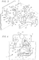
- an interface 1 comprises an insulating housing attached on the one hand to the insulating housing of a differential switch 2 and on the other hand to the insulating housing of an electrical auxiliary 3.
- the differential switch 2 is of known type comprising a lever mechanism 40 for actuating a contact-carrying shaft between an open position and a closed position and vice versa, and a differential detector with electrically connected transformer-summator to a trip relay (not detailed) allowing an automatic opening of said switch.
- this relay acts on a triggering mechanism so as to break a latch holding the contact carrier shaft, which causes the latter to rotate towards its open position.
- the mechanism of the differential switch 2 is coupled to the interface 1 by two mechanical connections: a shaft 6 extending the contact-carrying shaft of the switch axially, to transmit the rotation of this contact-carrying shaft to the interface , and a coupling pin 11 connected to a member of the triggering mechanism of the differential switch, for transmitting a triggering order from the interface to the switch.
- the member of the triggering mechanism of the differential switch to which the coupling pin 11 ends is the member which breaks the attachment holding of the contact-carrying shaft.
- the shaft 6 can be fixed end to end with the contact-holding shaft for example using a tenon and mortise couple (not shown).
- the electrical auxiliary 3 is for example an undervoltage release, the mechanism of which is capable of passing from an engaged position to a triggered position, a lever 41 allowing said trigger 3 to be reset.
- the trigger mechanism of the auxiliary 3 is coupled to the mechanism of the interface 1 by a coupling pin 10 connected to a trigger member of said mechanism of the auxiliary.
- the shaft 6 crosses the housings of the switch 2 and of the interface 1 by means of holes of suitable shape.
- the coupling fingers 10 and 11 pass through the walls of the interface and, respectively, of the auxiliary 3 and the switch 2, by means of holes, respectively 7 and 8, of oblong shapes adapted to the races. respective of these fingers.
- auxiliaries, triggers or switches can be coupled and coupled to the auxiliary 3, so that the movements of their trigger mechanisms are controlled by that of the auxiliary 3.
- an auxiliary 4 for example an auxiliary of the fault signal contact type, is attached to the auxiliary 3 and coupled to the latter by a mechanical connection 9, which connects the triggering member of the auxiliary 3 linked to the finger d coupling 10 to a corresponding member of the auxiliary 4.
- the insulating housing of the interface 1 contains a mechanism 5, shown in exploded perspective in FIG. 3.
- the shaft 6 for connection with the contact-carrying shaft of the switch 2 forms an integral part of a link 16, an elongated flange extending the end of said shaft, perpendicular to the latter .
- the shaft 6 passes through a bore 12 of the interface box, a bore which is extended by a projecting element 13, in the form of a hollow cylinder, which extends up to the travel zone of the elongated flange part of the link 16.
- this elongated flange part On the free end of this elongated flange part is provided a notch 17 forming an open oblong housing extending radially.
- This oblong housing 17 is adapted to receive a finger 21 of a lever 20.
- the lever 20 has a body 20B comprising an upper part of generally parallelepiped shape of which only one dorsal portion is extended downward, so as to form a shoulder 27.
- the upper part of the body 20B is traversed by a transverse bore 24 adapted to receive the hinge pin 31 of the lever 30.
- the lever 20 also includes a radial arm 20A which, starting from a lateral face of the upper part of this body 20, extends upward in an arc, as can be seen in FIGS. 3 and 4 .
- This radial arm 20A carries at its end the finger 21 for connection with the link 16.
- This finger 21 extends transversely on either side of the arm 20A.
- the part of this finger extending from the side of the body 20B is engaged with the oblong housing 17 of the link 16.
- the other part of this finger 21 is engaged with a window 15 formed in the housing, this making it possible to limit the movement of said axis.
- the lever 20 finally comprises, at the lower part of the body 20B, an arm 26, in the form of a plate bent at a right angle.
- This arm 26 leaves from the lateral side of the body 20B opposite to that on which the arm 20A leaves.
- a stud 25, extending transversely, is formed on the external surface of the bent end of the arm 26.
- the axes of the finger 21, the bore 24 and the stud 25 are in the same plane and the substantially radial surface 23 of the shoulder 27 extends parallel to this plane, as can be seen in FIG. 4.
- This lever 20 is articulated on a lever 30, itself mounted to pivot about a fixed axis of the interface box. 1.
- the lever 30 comprises a body 30A, of generally parallelepiped shape inside which is provided a housing adapted to receive a transverse axis 36 formed on the housing of the interface 1, as seen in FIG. 3.
- This body 30A is adapted to the size of the shoulder 27 located in the body 20B of the lever 20.
- the lever 30 also includes a radial arm 30B, in the form of an elongated flange, starting from a lateral side of the body 30A.
- This arm 30B carries, on one of its lateral sides, the finger 10, extending transversely, forming a coupling finger with the mechanism of the auxiliary 3. It carries, on its other lateral side, a stud 31, extending transversely, in engagement with the bore 24 of the lever 20, so as to form an axis of articulation of the latter.
- a shoulder 32 is provided under the arm 30B. This shoulder is of a shape adapted to receive the bent end of the arm 26 of the lever 20.
- a link 50 is pivotally mounted on the lever 20, the stud 25 of the latter being engaged with a bore 51 formed on one end of said link 50.
- this link is in the form of an elongated flange, a rear part, the end of which receives the stud 25, being slightly inclined downward relative to the rest of said link.
- the other end of the rod 50 is linked to a pivoting element 60, a transverse bore 52 of this rod receiving free rotation of a stud 61 of said pivoting element 60.
- the latter comprises a cylinder 60B rotating around a transverse axis 62 carried by the interface box 1, as seen in FIG. 3.
- the pivoting element 60 also comprises two radial arms 60A and 60C, acting at the level of one and the other respectively of the ends of the cylinder 60B, parallel, and extending in opposite directions.
- the end of the radial arm 60C carries the stud 61 in engagement with the bore 52 of the rod 50.
- the end of the radial arm 60A carries the transverse finger 11, forming a coupling finger with the triggering mechanism of the differential switch.
- the lever 20 abuts against the lever 30. More specifically, the body 30A of the lever 30 is housed under the upper part of the body 20B, by means of the shoulder 27, the substantially radial surface 35 of said body 30A abutting against the substantially radial surface 23 of the body 20B.
- the bent end of the arm 26 of the lever 20 is against the body 30A, by means of the shoulder 32.
- the finger 21 is located, on the one hand, in an upper portion of the oblong housing 17 of the link 16, as seen in FIG. 4, and, on the other hand, in abutment on a small side of the window 15 , more precisely its left side in the representation of FIG. 3.
- the finger 10 is located at the left end, in the representation of FIG. 4, of the oblong opening 7.
- the finger 11 is located at the right end, in the representation of FIG. 4, of the oblong opening 8.
- the link 16 then acts on the lever 20, via the finger 21, in connection with the pivot sliding in the housing 17.
- the lever 20 will drive the lever 30 in rotation about the axis 36, this rotation being made in a clockwise direction, if one refers to FIGS. 4 and 6.
- the two levers 20 and 30 will pivot together, without relative movement of one relative to the other, their respective surfaces 23 and 35 remaining in abutment against one another.
- the stud 25 therefore does not move during the movement of the levers 20 and 30, its axis remaining in alignment with the axis 36 around which the rotation takes place.
- the movement of the coupling finger 10 triggers the auxiliary 3 and, via the link 9, the auxiliary 4.
- This rest position corresponds to the open position of the differential switch and to the tripped position of the auxiliaries.
- the triggering auxiliary 3 When, starting from the rest position of FIG. 4, the triggering auxiliary 3 issues a triggering order, its triggering mechanism will pass from an engaged state to a triggered state, consequently causing the displacement of the coupling finger 10 towards the right end, in the representation of FIGS. 4 at 6, from the oblong opening 7.
- the lever 20 is held at its upper part by the link 16, which is itself held in position by the contact-carrying shaft of the differential switch 2. Consequently, the pivoting, clockwise, of the lever 30 will cause the lever 20 to pivot about the hinge pin 31 between these two levers. This pivoting is done counterclockwise, if one refers to Figures 4 to 6.
- the connecting rod formed by the two levers 20 and 30 behaves, in a way, like a pair of scissors which opens.
- the two levers 20 and 30 are then in a position of maximum relative opening.
- This displacement of the stud 25 causes the displacement of the rod 50 which will act on the pivoting element 60, causing it to rotate in a counterclockwise direction, if reference is made to FIGS. 4 to 6.
- the finger 11 then moves towards the left end, in the representation of FIGS. 4 to 6, of the oblong opening 8. This movement of the finger 11 actuates the triggering mechanism of the differential switch 2.
- the lever 20 By pivoting, the lever 20 returns the connecting rod assembly constituted by the link 50 and the pivoting element 60 to its initial position. Therefore, once the differential switch is open, the finger 11 stops transmitting to its mechanism a trigger order.
- the interface mechanism After the rotational movement of the contact-carrying shaft, the interface mechanism is again in the rest position shown in FIG. 6 and described above.
- the pivot axis of the link 16 is in the plane common to the axis 36 and to the axes of the finger 21 and the stud 25. Consequently, the oblong housing 17 extends radially not only with respect to the pivot axis of the link 17, but also with respect to the axes 31 and 36.
- interface 1 a device for signaling the open or closed position of the contacts of the differential switch.
- the blade 76 of such a device is pivotable by one of its ends, so as to be able to struggle between two positions in which its other end is in contact with, respectively, a stud 77 and a pad 78.
- the blade 76 is engaged with a spring which urges it toward the pad 77 or toward the pad 78, depending on its position relative to the median plane between said pads.
- This device 79 is part of an electrical circuit (not shown) in which it acts as a switch.
- This circuit may include a diode which will be in the off or on position depending on whether the blade 76 is in contact with one or the other pad 77 and 78.
- it will comprise two diodes indicating respectively that the contacts are closed and open, and the ignition of which will be subject to contact of the blade with the pad 77 for one and the pad 78 for the other.
- a lever 70 is pivotally mounted on the fixed axis 36 of the interface 1 housing.
- this lever comprises, starting from a heel 72 provided with a bore with which the pin 36 is engaged, a leg 70A and a foot 70B.
- a cam surface 71 On the end of the leg 70A is provided a cam surface 71.
- the foot 70B for its part, comprises, at its lower end, curved downward, two fingers 74 and 75, extending transversely one above the other, with a slight offset, as can be seen, by example, in Figure 4.
- a lug 73 on which is installed the end of a bias spring 80, the other end of which is engaged with a lug 82 formed on the radial arm 20A of the lever 20.
- the blade 76 of the device is in abutment, against the stud 77 while the finger 74 of the foot of the lever 70 having served to bring it into this position is located near the blade 76.
- This device therefore makes it possible to signal, via the diodes, whether the differential switch is in the open or closed position.
- the advantage is that it draws this information directly from the position of the finger 21, linked directly to the contact-carrying shaft of the differential switch. This allows in particular, as we will see now, to correctly account for the exceptional case where the contacts would be stuck in the differential switch.
- the movements of the levers 40, 41 and 42 are secured to a lever 43 installed on the housing of the interface 1.
- the control of the modular assembly is simplified.
Landscapes
- Breakers (AREA)
- Switches With Compound Operations (AREA)
- Steering Controls (AREA)
- Mechanisms For Operating Contacts (AREA)
Applications Claiming Priority (2)
| Application Number | Priority Date | Filing Date | Title |
|---|---|---|---|
| FR9312612 | 1993-10-22 | ||
| FR9312612A FR2711840B1 (fr) | 1993-10-22 | 1993-10-22 | Interface d'adaptation pour interrupteur différentiel multipolaire. |
Publications (2)
| Publication Number | Publication Date |
|---|---|
| EP0650178A1 true EP0650178A1 (de) | 1995-04-26 |
| EP0650178B1 EP0650178B1 (de) | 1998-12-30 |
Family
ID=9452119
Family Applications (1)
| Application Number | Title | Priority Date | Filing Date |
|---|---|---|---|
| EP19940402356 Expired - Lifetime EP0650178B1 (de) | 1993-10-22 | 1994-10-20 | Schnittstelle zur Anpassung für mehrpolige Differentialschalter |
Country Status (4)
| Country | Link |
|---|---|
| EP (1) | EP0650178B1 (de) |
| DE (1) | DE69415629T2 (de) |
| ES (1) | ES2126085T3 (de) |
| FR (1) | FR2711840B1 (de) |
Cited By (5)
| Publication number | Priority date | Publication date | Assignee | Title |
|---|---|---|---|---|
| EP0777251A1 (de) | 1995-12-01 | 1997-06-04 | Legrand | Schnittstelle zur Anpassung zwischen Differentialschalter und elektrisches Hilfmittel |
| EP1814133A1 (de) * | 2006-01-25 | 2007-08-01 | Mitsubishi Electric Corporation | Schaltvorrichtung |
| WO2007088003A1 (de) * | 2006-01-31 | 2007-08-09 | Moeller Gmbh | Mehrpoliges schaltgerät mit zusatzgehäuse und gegenseitige mechanische verriegelungs vorrichtung |
| FR3031233A1 (fr) * | 2014-12-30 | 2016-07-01 | Legrand France | Appareil modulaire a securite renforcee et ensemble electrique auto-protege comprenant un tel appareil modulaire assemble a un disjoncteur |
| FR3031234A1 (fr) * | 2014-12-30 | 2016-07-01 | Legrand France | Appareil modulaire a pion de liaison retractable et ensemble electrique auto-protege comprenant un tel appareil modulaire assemble a un disjoncteur |
Citations (4)
| Publication number | Priority date | Publication date | Assignee | Title |
|---|---|---|---|---|
| US2779831A (en) * | 1954-06-14 | 1957-01-29 | Gen Electric | Multipole electric circuit breakers |
| US3421128A (en) * | 1966-05-17 | 1969-01-07 | Gen Electric | Series-connected electrical circuit breaker assembly |
| FR2615323A1 (fr) * | 1987-05-11 | 1988-11-18 | Merlin Gerin | Disjoncteur modulaire a bloc declencheur auxiliaire associe a un bloc disjoncteur multipolaire |
| WO1993018535A1 (de) * | 1992-03-10 | 1993-09-16 | Heinrich Kopp Ag | Verbindungselement für mehrpolige schutzschaltgeräte |
-
1993
- 1993-10-22 FR FR9312612A patent/FR2711840B1/fr not_active Expired - Fee Related
-
1994
- 1994-10-20 ES ES94402356T patent/ES2126085T3/es not_active Expired - Lifetime
- 1994-10-20 DE DE1994615629 patent/DE69415629T2/de not_active Expired - Fee Related
- 1994-10-20 EP EP19940402356 patent/EP0650178B1/de not_active Expired - Lifetime
Patent Citations (4)
| Publication number | Priority date | Publication date | Assignee | Title |
|---|---|---|---|---|
| US2779831A (en) * | 1954-06-14 | 1957-01-29 | Gen Electric | Multipole electric circuit breakers |
| US3421128A (en) * | 1966-05-17 | 1969-01-07 | Gen Electric | Series-connected electrical circuit breaker assembly |
| FR2615323A1 (fr) * | 1987-05-11 | 1988-11-18 | Merlin Gerin | Disjoncteur modulaire a bloc declencheur auxiliaire associe a un bloc disjoncteur multipolaire |
| WO1993018535A1 (de) * | 1992-03-10 | 1993-09-16 | Heinrich Kopp Ag | Verbindungselement für mehrpolige schutzschaltgeräte |
Cited By (8)
| Publication number | Priority date | Publication date | Assignee | Title |
|---|---|---|---|---|
| EP0777251A1 (de) | 1995-12-01 | 1997-06-04 | Legrand | Schnittstelle zur Anpassung zwischen Differentialschalter und elektrisches Hilfmittel |
| FR2741992A1 (fr) * | 1995-12-01 | 1997-06-06 | Legrand Sa | Interface d'adaptation a inserer entre un interrupteur differentiel et un auxiliaire electrique |
| EP1814133A1 (de) * | 2006-01-25 | 2007-08-01 | Mitsubishi Electric Corporation | Schaltvorrichtung |
| WO2007088003A1 (de) * | 2006-01-31 | 2007-08-09 | Moeller Gmbh | Mehrpoliges schaltgerät mit zusatzgehäuse und gegenseitige mechanische verriegelungs vorrichtung |
| FR3031233A1 (fr) * | 2014-12-30 | 2016-07-01 | Legrand France | Appareil modulaire a securite renforcee et ensemble electrique auto-protege comprenant un tel appareil modulaire assemble a un disjoncteur |
| FR3031234A1 (fr) * | 2014-12-30 | 2016-07-01 | Legrand France | Appareil modulaire a pion de liaison retractable et ensemble electrique auto-protege comprenant un tel appareil modulaire assemble a un disjoncteur |
| EP3041022A1 (de) * | 2014-12-30 | 2016-07-06 | Legrand France | Modulares gerät mit einziehbarem verbindungszapfen, und selbstgeschützte elektrische anlage, die ein solches modulares gerät verbunden mit einem schutzschalter umfasst |
| EP3041021A1 (de) * | 2014-12-30 | 2016-07-06 | Legrand France | Modulares gerät mit erhöhter sicherheit, und selbstgeschützte elektrische anlage, die ein solches modulares gerät verbunden mit einem schutzschalter umfasst |
Also Published As
| Publication number | Publication date |
|---|---|
| FR2711840A1 (fr) | 1995-05-05 |
| ES2126085T3 (es) | 1999-03-16 |
| DE69415629D1 (de) | 1999-02-11 |
| EP0650178B1 (de) | 1998-12-30 |
| FR2711840B1 (fr) | 1996-01-26 |
| DE69415629T2 (de) | 1999-06-24 |
Similar Documents
| Publication | Publication Date | Title |
|---|---|---|
| EP0295155B1 (de) | Modulschutzschalter, bestehend aus einem mit einem mehrpoligen Leistungsschutzschalterblock zusammenwirkenden Auslöseblock | |
| FR2534412A1 (fr) | Interrupteur electrique avec arret de course du levier de commande en cas de soudure des contacts | |
| FR2900498A1 (fr) | Disjoncteur de circuit | |
| EP2131378B1 (de) | Steuervorrichtung für ein elektrisches Schaltgerät, das mit einer Signalisierungsvorrichtung für die Verschweißung der Kontakte ausgestattet ist, und mit dieser Vorrichtung ausgestattetes elektrisches Schaltgerät | |
| EP0205361B1 (de) | Handbetätigte Schnapp-Schliesseinrichtung eines Miniaturschutzschalters | |
| EP0338930A1 (de) | Lastschalter oder Differential-Lastschalter | |
| EP0326446B1 (de) | Steuer- und Signalhilfsschalter für mehrpoligen Modulschalter | |
| FR2605454A1 (fr) | Mecanisme de commande d'un disjoncteur electrique miniature a rearmement automatique | |
| EP0650178B1 (de) | Schnittstelle zur Anpassung für mehrpolige Differentialschalter | |
| EP0612092B1 (de) | Schutzschalter mit anpassbarer Fernbetätigungseinheit | |
| EP2717284B1 (de) | Bedienungsvorrichtung eines elektrischen Schutzschaltgeräts, und diese umfassendes elektrisches Schutzschaltgerät | |
| CH686853A5 (fr) | Appareil interrupteur de protection accouplable à un module de commande et/ou à un module de signalisation. | |
| EP0325501B1 (de) | Automatische Schalter, insbesondere Differential- und Schutzschaltern | |
| FR2614467A1 (fr) | Appareil interrupteur de protection a mecanisme de declenchement simplifie | |
| EP0798756A1 (de) | Betätigungsmechanismus für elektrischen Schutzschalter mit grossen Öffnungswinkel | |
| EP1665316B1 (de) | Abschalteinrichtung für elektrischen strom mit vollständiger unterscheidung von zuständen | |
| FR2649826A1 (fr) | Mecanisme de commande pour disjoncteur electrique | |
| EP0951044B1 (de) | Hilfseinheit mit einer Anzeigevorrichtung anpassbar für einen Leistungschutzschalter | |
| FR2628261A1 (fr) | Disjoncteur a mecanisme a franchissement de point mort | |
| FR2656155A1 (fr) | Auxiliaire d'adaptation pour interrupteur differentiel multipolaire. | |
| EP1515352B1 (de) | Vorrichtung zur elektrischen Stromabschaltung mit einem translatorisch bewegbaren Kontakt | |
| EP0032870B1 (de) | Auf ein Gestell montierbares Gerät zum Steuern der Bewegung eines Armes und Anwendung dieses Gerätes als Schalter | |
| FR2600210A1 (fr) | Disjoncteur a deux circuits de commutation dont l'un est protege | |
| EP2810294A1 (de) | Elektrische leitungsschutzvorrichtung mit versetzter sperre | |
| EP0327460A1 (de) | Elektrischer Schalter mit automatischer Ausschaltung, insbesondere Differentialschutz |
Legal Events
| Date | Code | Title | Description |
|---|---|---|---|
| PUAI | Public reference made under article 153(3) epc to a published international application that has entered the european phase |
Free format text: ORIGINAL CODE: 0009012 |
|
| AK | Designated contracting states |
Kind code of ref document: A1 Designated state(s): DE ES FR GB IT |
|
| 17P | Request for examination filed |
Effective date: 19950621 |
|
| GRAG | Despatch of communication of intention to grant |
Free format text: ORIGINAL CODE: EPIDOS AGRA |
|
| GRAG | Despatch of communication of intention to grant |
Free format text: ORIGINAL CODE: EPIDOS AGRA |
|
| GRAH | Despatch of communication of intention to grant a patent |
Free format text: ORIGINAL CODE: EPIDOS IGRA |
|
| 17Q | First examination report despatched |
Effective date: 19980327 |
|
| GRAH | Despatch of communication of intention to grant a patent |
Free format text: ORIGINAL CODE: EPIDOS IGRA |
|
| GRAA | (expected) grant |
Free format text: ORIGINAL CODE: 0009210 |
|
| AK | Designated contracting states |
Kind code of ref document: B1 Designated state(s): DE ES FR GB IT |
|
| GBT | Gb: translation of ep patent filed (gb section 77(6)(a)/1977) |
Effective date: 19981231 |
|
| REF | Corresponds to: |
Ref document number: 69415629 Country of ref document: DE Date of ref document: 19990211 |
|
| REG | Reference to a national code |
Ref country code: ES Ref legal event code: FG2A Ref document number: 2126085 Country of ref document: ES Kind code of ref document: T3 |
|
| ITF | It: translation for a ep patent filed |
Owner name: FUMERO BREVETTI S.N.C. |
|
| PLBE | No opposition filed within time limit |
Free format text: ORIGINAL CODE: 0009261 |
|
| STAA | Information on the status of an ep patent application or granted ep patent |
Free format text: STATUS: NO OPPOSITION FILED WITHIN TIME LIMIT |
|
| 26N | No opposition filed | ||
| REG | Reference to a national code |
Ref country code: GB Ref legal event code: IF02 |
|
| PGFP | Annual fee paid to national office [announced via postgrant information from national office to epo] |
Ref country code: GB Payment date: 20051007 Year of fee payment: 12 |
|
| PGFP | Annual fee paid to national office [announced via postgrant information from national office to epo] |
Ref country code: ES Payment date: 20051013 Year of fee payment: 12 |
|
| PGFP | Annual fee paid to national office [announced via postgrant information from national office to epo] |
Ref country code: DE Payment date: 20061009 Year of fee payment: 13 |
|
| PGFP | Annual fee paid to national office [announced via postgrant information from national office to epo] |
Ref country code: IT Payment date: 20061031 Year of fee payment: 13 Ref country code: FR Payment date: 20061031 Year of fee payment: 13 |
|
| REG | Reference to a national code |
Ref country code: FR Ref legal event code: CD |
|
| GBPC | Gb: european patent ceased through non-payment of renewal fee |
Effective date: 20061020 |
|
| PG25 | Lapsed in a contracting state [announced via postgrant information from national office to epo] |
Ref country code: GB Free format text: LAPSE BECAUSE OF NON-PAYMENT OF DUE FEES Effective date: 20061020 |
|
| REG | Reference to a national code |
Ref country code: ES Ref legal event code: FD2A Effective date: 20061021 |
|
| PG25 | Lapsed in a contracting state [announced via postgrant information from national office to epo] |
Ref country code: ES Free format text: LAPSE BECAUSE OF NON-PAYMENT OF DUE FEES Effective date: 20061021 |
|
| PG25 | Lapsed in a contracting state [announced via postgrant information from national office to epo] |
Ref country code: DE Free format text: LAPSE BECAUSE OF NON-PAYMENT OF DUE FEES Effective date: 20080501 |
|
| REG | Reference to a national code |
Ref country code: FR Ref legal event code: ST Effective date: 20080630 |
|
| PG25 | Lapsed in a contracting state [announced via postgrant information from national office to epo] |
Ref country code: FR Free format text: LAPSE BECAUSE OF NON-PAYMENT OF DUE FEES Effective date: 20071031 |
|
| PG25 | Lapsed in a contracting state [announced via postgrant information from national office to epo] |
Ref country code: IT Free format text: LAPSE BECAUSE OF NON-PAYMENT OF DUE FEES Effective date: 20071020 |