EP0650034A1 - Durchflussmesser nach dem Ultraschall-Prinzip - Google Patents
Durchflussmesser nach dem Ultraschall-Prinzip Download PDFInfo
- Publication number
- EP0650034A1 EP0650034A1 EP94115757A EP94115757A EP0650034A1 EP 0650034 A1 EP0650034 A1 EP 0650034A1 EP 94115757 A EP94115757 A EP 94115757A EP 94115757 A EP94115757 A EP 94115757A EP 0650034 A1 EP0650034 A1 EP 0650034A1
- Authority
- EP
- European Patent Office
- Prior art keywords
- flow
- flow channel
- reflector
- ultrasonic
- usw2
- Prior art date
- Legal status (The legal status is an assumption and is not a legal conclusion. Google has not performed a legal analysis and makes no representation as to the accuracy of the status listed.)
- Granted
Links
Images


Classifications
-
- G—PHYSICS
- G01—MEASURING; TESTING
- G01F—MEASURING VOLUME, VOLUME FLOW, MASS FLOW OR LIQUID LEVEL; METERING BY VOLUME
- G01F1/00—Measuring the volume flow or mass flow of fluid or fluent solid material wherein the fluid passes through a meter in a continuous flow
- G01F1/66—Measuring the volume flow or mass flow of fluid or fluent solid material wherein the fluid passes through a meter in a continuous flow by measuring frequency, phase shift or propagation time of electromagnetic or other waves, e.g. using ultrasonic flowmeters
- G01F1/662—Constructional details
Definitions
- the invention relates to a mass flow meter based on an ultrasonic flow meter.
- the previously known ultrasonic transducers have an almost Gaussian sensitivity distribution. Their maximum sensitivity is at the center. It decreases sharply towards the edge.
- Another problem with the ultrasonic transducers known to date is the divergence of the wavefront of the transmitted US signal. The degree of divergence is due to the converter, but cannot be suppressed.
- the sensitivity distribution is strongly influenced by the properties of the pipe wall when irradiation is carried out through the pipe wall.
- a further disadvantage of the flow meter described in DE 40 10 148 A1 is that the ultrasonic signal can not only spread in a W-shape but also on a parasitic V-shaped path due to the measuring tube structure, and therefore additional measures to suppress the resulting signal components required are.
- the invention has for its object to provide a device which has a higher measurement accuracy and whose measurement signal depends only on the flow and no longer on the type of fluid used and the current flow profile.
- the measuring device is particularly suitable for flow channels with a large diameter (> 50 mm).
- the object is achieved in that a hollow mirror-shaped reflector is introduced into the ultrasonic wave path. Its orientation is chosen so that its focal point coincides with the center of the radiation surface of the ultrasonic transducer. It is thereby achieved that the ultrasonic waves striking the concave reflector are reflected in phase and parallel to one another.
- Two ultrasonic transducers USW 1 and USW2 to be operated in an alternating sequence as transmitters and receivers are arranged on the walls of the flow channel SK (see FIG. 2) through which flow flows in any direction F.
- the flow channel SK on the side opposite to USW1 and USW2 is shaped such that the signal radiated into the flow channel SK by the ultrasonic transducers USW1, USW2 spreads out in a W-shape.
- two reflectors R1, R2 are attached in the flow channel SK.
- the reflectors R1 and R2 are partial areas of the rotation paraboloids RK1 and RK2 lying outside the central area, the main axes HA1 and HA2 of which each include an angle ⁇ with the axis of symmetry SA of the flow channel SK.
- the ultrasound signal emitted by the ultrasound transducer USW1 is reflected on the first reflector R1, on the flow channel ceiling SKD and on the second reflector R2 and then strikes the receiver, the ultrasound transducer USW2.
- the ultrasound transducers USW1, USW2 are located in the focal point BP1, BP2 of the rotational paraboloids RK1 and RK2, the ultrasound waves are reflected in parallel on the reflector R1 opposite the US transducer USW1 and in the center of the reflector R2 opposite the US transducer USW2 Converter area focused.
- the measure mentioned above results in a uniform evaluation of the flow velocities prevailing in the flow channel SK.
- the shape shown in FIG. 4 has proven to be a suitable reflector geometry.
- the exemplary embodiment relates to a flow channel SK with a rectangular cross section and one-sided bulge (FIG. 2).
- the size and position of the offset parabolic mirror R1 must be calculated from the reflection angle ⁇ resulting from the ultrasound transducer distance 1 and the height h, at which the reflection surface of the flow channel SK is inclined.
- the parameters of the mirror R1 are calculated as follows (Fig.
- a rectangular flow channel cross section was chosen.
- a square, round or oval cross section is also conceivable.
- the flow channel wall between the two ultrasonic transducers is no longer suitable as a reflection surface. Rather, another, but flat reflector should be attached here.
- the measuring device according to the invention is not only suitable for the flow measurement of a wide variety of liquids, but also for the flow measurement of a wide variety of gases and also for the water flow meters in heating / cooling systems, which are referred to as heat meters.
- the invention can be used to advantage particularly in the case of flow ducts with a large diameter (> 50 mm), since in this case the ratio of transducer diameter to flow duct diameter becomes small (1: 5 ... 1:10).
- the reflection angles from the edge of the reflector R1 to the edge of the ultrasonic transducer do not differ much from those to the focal point BP (the center of the ultrasonic transducer), i.e. the mirror properties are better used.
- the reflectors can be made of metal or plastic, advantageously of an injection-molded plastic. Soft materials such as e.g. Rubber.
- a further improvement in measuring accuracy can be achieved by connecting two measuring devices in series.
- the second measuring device is rotated by 90 ° about the longitudinal axis of the flow channel in relation to the first measuring device.
- Such a construction is expediently chosen when the fluid flows helically through the flow channel SK, which can be caused, for example, by two successive line elbows.
- Suitable ultrasonic transducers advantageously have a diameter of less than 10 mm.
- the operating frequency is approximately 2 MHz.
Landscapes
- Physics & Mathematics (AREA)
- Electromagnetism (AREA)
- Fluid Mechanics (AREA)
- General Physics & Mathematics (AREA)
- Measuring Volume Flow (AREA)
- Ultra Sonic Daignosis Equipment (AREA)
- Measurement Of Velocity Or Position Using Acoustic Or Ultrasonic Waves (AREA)
- Measuring Pulse, Heart Rate, Blood Pressure Or Blood Flow (AREA)
- Pressure-Spray And Ultrasonic-Wave- Spray Burners (AREA)
- Transducers For Ultrasonic Waves (AREA)
Abstract
Description
- Die Erfindung betrifft einen Massendurchflußmesser auf der Basis eines Ultraschalldurchflußmessers.
- Bei der Durchflußmessung von bewegten flüssigen oder gasförmigen Medien (Fluiden) mit Ultraschall besteht das Problem, daß das vom Empfänger (Ultraschallwandler) gelieferte Meßsignal nicht nur vom Durchfluß, sondern auch vom jeweiligen Strömungsprofil im Meßrohr und der Art des durchströmenden Fluids abhängt. Je nach Strömungsgeschwindigkeit ergeben sich verschiedene Strömungsprofile. Das in Figur 1a gezeigte laminare Strömungsprofil in einem Rohr mit viereckigem Querschnitt tritt bei langsamer Strömungsgeschwindigkeit auf. Die im Inneren des Rohres eingezeichneten Linien veranschaulichen Bereiche gleicher Strömungsgeschwindigkeit. Laminare Strömungsprofile können durch eine parabolische Form, vgl. Figur 1c, beschrieben werden. Die höchsten Strömungsgeschwindigkeiten treten in der Rohrmitte auf. Je größer der Durchfluß, also je höher die Strömungsgeschwindigkeit ist, desto mehr nähert sich das Strömungsprofil einer Kastenform an. Figur 1b zeigt ein turbulentes Strömungsprofil, das bei hohen Strömungsgeschwindigkeiten auftritt. In weiten Bereichen des Rohres bleibt die Strömungsgeschwindigkeit in etwa gleich.
- Die bisher bekannten Ultraschallwandler haben eine annähernd gaußförmige Empfindlichkeitsverteilung. Deren maximale Empfindlichkeit liegt in deren Zentrum. Zum Rand hin nimmt sie stark ab. Ein weiteres Problem bei den bisher bekannten Ultraschallwandlern liegt in der Divergenz der Wellenfront des ausgesandten US-Signals. Der Grad der Divergenz ist wandlerbedingt, läßt sich aber nicht unterdrücken. Zusätzlich wird die Empfindlichkeitsverteilung durch die Rohrwandeigenschaften stark beeinflußt, wenn durch die Rohrwand eingestrahlt wird.
- Beschallt man nun mit einem Ultraschallwandler in einem Strömungskanal das bewegte Medium, wie dies aus der DE 40 10 148 A1 bekannt ist, um aus der Schallaufzeit oder mittels des Dopplereffekts die Strömungsgeschwindigkeit zu bestimmen, so wird, insbesondere bei laminarem Strömungsprofil, die in der Strömungskanalmitte auftretende höchste Strömungsgeschwindigkeit starker bewertet als die am Rand des Strömungskanals auftretende niedrigere Strömungsgeschwindigkeit. Dies hat zur Folge, daß sich für jedes Strömungsprofil und für jedes Fluid ein anders Meßsignal ergibt, was dessen Auswertung erschwert.
- Weiterhin ist bei dem in der DE 40 10 148 A1 beschriebenen Durchflußmesser von Nachteil, daß das Ultraschallsignal sich aufgrund des Meßrohraufbaus nicht nur w-förmig, sondern auch auf einem parasitären v-förmigen Weg ausbreiten kann und deshalb zusätzliche Maßnahmen zur Unterdrückung der daraus resultierenden Signalanteile erforderlich sind.
- Der Erfindung liegt die Aufgabe zugrunde, eine Vorrichtung zu schaffen, die eine höhere Meßgenauigkeit hat und deren Meßsignal nurmehr vom Durchfluß und nicht mehr von der Art des verwendeten Fluids und dem vorliegenden Strömungsprofil abhängt.
- Die Meßvorrichtung eignet sich besonders für Strömungskanäle mit großem Durchmesser (> 50 mm).
- Die Aufgabe wird erfindungsgemäß durch eine Vorrichtung gemäß dem Patentanspruch 1 gelöst.
- Vorteilhafte Weiterbildungen der Erfindung ergeben sich aus den abhängigen Ansprüchen.
- Die Aufgabe wird dadurch gelöst, daß in den Ultraschallwellenweg ein hohlspiegelförmiger Reflektor eingebracht wird. Dessen Orientierung ist so gewählt, daß dessen Brennpunkt mit dem Zentrum der Abstrahlfläche des Ultraschallwandlers zusammenfällt. Damit wird erreicht, daß die auf den hohlspiegelförmigen Reflektor treffenden Ultraschallwellen gleichphasig und parallel zueinander reflektiert werden.
- Anhand der Figuren soll die Erfindung näher erläutert werden.
- Figur 1a, b, c
- zeigt ein laminares und ein turbulentes Strömungsprofil im Strömungskanalquerschnitt und mögliche Strömungsprofile im Strömungskanal in der Seitenansicht.
- Figur 2
- zeigt den prinzipiellen Aufbau der Meßvorrichtung.
- Figur 3
- zeigt die geometrischen Zusammenhänge der im Strömungskanal angebrachten hohlspiegelförmigen Reflektoren.
- Figur 4
- zeigt ein Ausführungsbeispiel eines hohlspiegelförmigen Reflektors.
- Figur 5 und 6
- zeigen weitere Möglichkeiten zur Anordnung der US-Wandler.
- An den Wanden des in beliebiger Richtung F durchflossenen Strömungskanals SK (vergl. Figur 2) sind zwei in alternierender Folge als Sender und Empfänger zu betreibende Ultraschallwandler USW 1 und USW2 angeordnet. Auf der den Ultraschallwandlern USW1 und USW2 gegenüberliegenden Seite ist der Strömungskanal SK so geformt, daß das von den Ultraschallwandlern USW1, USW2 in den Strömungskanal SK eingestrahlte Signal sich w-förmig ausbreitet. Weiterhin sind im Strömungskanal SK zwei Reflektoren R1, R2 angebracht. Die Reflektoren R1 und R2 sind jeweils außerhalb des zentralen Bereichs liegende Teilflächen der Rotationsparaboloide RK1 und RK2, deren Hauptachsen HA1 und HA2 jeweils einen Winkel φ mit der Symmetrieachse SA des Strömungskanals SK einschließen. Das vom Ultraschallwandler USW1 ausgesendete Ultraschallsignal wird am ersten Reflektor R1, an der Strömungskanaldecke SKD und am zweiten Reflektor R2 reflektiert und trifft dann auf den Empfänger, den Ultraschallwandler USW2. Weil die Ultraschallwandler USW1, USW2 sich im Brennpunkt BP1, BP2 der Rotationsparaboloide RK1 bzw. RK2 befinden, werden die Ultraschallwellen an dem dem US-Wandler USW1 gegenüberliegenden Reflektor R1 parallel reflektiert und an dem dem US-Wandler USW2 gegenüberliegenden Reflektor R2 in das Zentrum der Wandlerfläche fokussiert. Durch die obengenannte Maßnahme kommt es zu einer gleichmäßigen Bewertung der im Strömungskanal SK vorherrschenden Strömungsgeschwindigkeiten.
- Als geeignete Reflektorgeometrie hat sich die in Figur 4 gezeigte Form erwiesen. Das Ausführungsbeispiel bezieht sich auf einen Strömungskanal SK mit rechteckigem Querschnitt und einseitiger Ausbuchtung (Fig. 2). Zur Festlegung der Reflektorgeometrie muß aus dem sich aus dem Ultraschallwandlerabstand 1 und der Höhe h ergebenden Reflexionswinkel α, unter welchem die Reflexionsfläche des Strömungskanals SK geneigt ist, die Größe und Lage des Offset-Parabol-Spiegels R1 berechnet werden. Die Parameter des Spiegels R1 werden wie folgt berechnet (Fig. 3):

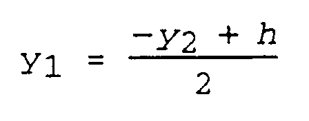

Hierbei ist die Höhe h die sich aus dem Lot auf die Strömungskanaldecke SKD im Brennpunkt BP1 und der dazu schräg verlaufenden Reflektorschnittfläche ergebende Entfernung. Der Fokusabstand ist mit f bezeichnet. Der Winkel φ ist der zum Winkel 2α komplementäre Winkel

Die Lage des Koordinatensystems für diese Beschreibung muß entsprechend der in der Figur 3 gezeigten gewählt werden. Die y-Achse des Koordinatensystems liegt parallel zur Hauptachse HA1 der parabolischen Raumkurve RK1. Entsprechendes gilt für die Lage des Reflektors R2 bezüglich des US-Wandlers USW2. - In dem Ausführungsbeispiel nach Fig. 2 wurde ein rechteckiger Strömungskanalquerschnitt gewählt. Genausogut ist ein quadratischer, runder oder ovaler Querschnitt denkbar. Bei rundem oder ovalem Querschnitt ist jedoch die Strömungskanalwand zwischen den beiden Ultraschallwandlern nicht mehr als Reflexionsfläche geeignet. Vielmehr sollte hier ein weiterer, jedoch ebener Reflektor angebracht werden.
- Die erfindungsgemäße Meßvorrichtung ist nicht nur für die Durchflußmessung verschiedenster Flüssigkeiten geeignet, sondern auch für die Durchflußmessung verschiedenster Gase und auch für die, als Wärmezähler bezeichneten, Wasser-Durchflußmesser in Heiz-/Kühlsystemen.
- Besonders bei Strömungskanälen mit großem Durchmesser (> 50 mm) kann die Erfindung vorteilhaft eingesetzt werden, da in diesem Fall das Verhältnis von Wandlerdurchmesser zu Strömungskanaldurchmesser klein wird (1:5...1:10). Dadurch bedingt unterscheiden sich die Reflexionswinkel vom Rand des Reflektors R1 zum Rand des Ultraschallwandlers nicht stark von denen bis zum Brennpunkt BP (dem Mittelpunkt des Ultraschallwandlers), d.h. die Spiegeleigenschaften werden besser genützt.
- Im nachfolgenden sind Variationsmöglichkeiten zum Aufbau der erfindungsgemäßen Meßvorrichtung angegeben:
- Wandler verschiedener Durchmesser
- Verhältnis von Wandlerdurchmesser zu Strömungskanaldurchmesser klein (1:5...1:10), dient wie oben beschrieben zur Homogenisierung des Schallfeldes
- Verhältnis Wandlerdurchmesser zu Strömungskanaldurchmesser ähnlich (1:1...1:3), dient der Signal-Intensitätssteigerung
- Aufgesetzte und/oder eingesetzte Wandler
- Kombination mit Mehrstrahlverfahren bei größeren Nennweiten (> 50 mm), wie z.B. in Fig. 5 in der Draufsicht gezeigt
- Kombination mit Strahlführungen in "V", "W" oder anderer Zickzack Form.
- quadratischer Strömungskanalquerschnitt
- rechteckiger Strömungskanalquerschnitt
- Polygonströmungskanalquerschnitt (z.B. Sechseck)
- ovaler oder runder Strömungskanalquerschnitt
- kombinierte Strömungskanalquerschnitte
- Sende- u. Empfangswandler auf einer Seite des Strömungskanals
- Sende- u. Empfangswandler gegenüberliegend
- Sende- u. Empfangswandler axial versetzt, wie z.B. in der Draufsicht in Fig. 6 gezeigt
- mehrere Sende- u. Empfangswandler verteilt auf verschiedenen Wänden des Strömungskanals
- Die Reflektoren können aus Metall oder aus Kunststoff, vorteilhafter Weise aus einem spritzgußfähigem Kunststoff bestehen.Nicht geeignet sind weiche Materialien wie z.B. Gummi.
- Eine weitere Verbesserung der Meßgenauigkeit läßt sich durch eine Serienschaltung zweier Meßvorrichtungen erzielen. Die zweite Meßvorrichtung ist dabei um 90° um die Längsachse des Strömungskanals gegenüber der ersten Meßvorrichtung gedreht. Sinnvoller Weise wird ein derartiger Aufbau dann gewählt, wenn das Fluid schraubenförmig durch den Strömungskanal SK strömt, was beispielsweise durch zwei aufeinander folgende Leitungskrümmer verursacht werden kann.
- Geeignete Ultraschallwandler haben vorteilhafter Weise einen Durchmesser kleiner als 10 mm. Die Betriebsfrequenz liegt bei ca. 2 MHz.
Claims (6)
- Vorrichtung zur Durchflußmessung in einem Strömungskanal (SK) mit einem ersten Ultraschallwandler (USW1) und einem zweiten Ultraschallwandler (USW2),
dadurch gekennzeichnet,- daß der erste Ultraschallwandler (USW1) und der zweite Ultraschallwandler (USW2) parallel zur Strömungskanalwand angeordnet sind und- daß im Strömungskanal (SK) ein erster hohlspiegelartiger Reflektor (R1) angeordnet ist. - Vorrichtung nach Anspruch 1,
dadurch gekennzeichnet,
daß der erste hohlspiegelartige Reflektor (R1) die Form eines Rotationsparaboloids hat. - Vorrichtung nach Anspruch 1 oder 2,
dadurch gekennzeichnet,
daß im Strömungskanal (SK) ein zweiter hohlspiegelartiger Reflektor (R2) angeordnet ist. - Vorrichtung nach Anspruch 3,
dadurch gekennzeichnet,
daß der zweite hohlspiegelartige Reflektor (R2) die Form eines Rotationsparaboloids hat. - Vorrichtung nach einem der vorigen Ansprüche,
dadurch gekennzeichnet,
daß die beiden Reflektoren (R1, R2) im Strömungskanal (SK) jeweils gegenüber den beiden Ultraschallwandlern (USW1, USW2) angeordnet sind. - Vorrichtung nach einem der vorigen Ansprüche,
dadurch gekennzeichnet,
daß der Strömungskanal (SK) auf der, den Ultraschallwandlern (USW1, USW2) gegenüberliegenden Seite eine wannenförmige Vertiefung aufweist, in welcher die Reflektoren (R1, R2) angeordnet sind.
Applications Claiming Priority (2)
| Application Number | Priority Date | Filing Date | Title |
|---|---|---|---|
| DE4336368A DE4336368C2 (de) | 1993-10-25 | 1993-10-25 | Vorrichtung zur Durchflußmessung |
| DE4336368 | 1993-10-25 |
Publications (2)
| Publication Number | Publication Date |
|---|---|
| EP0650034A1 true EP0650034A1 (de) | 1995-04-26 |
| EP0650034B1 EP0650034B1 (de) | 1999-07-21 |
Family
ID=6500963
Family Applications (1)
| Application Number | Title | Priority Date | Filing Date |
|---|---|---|---|
| EP94115757A Expired - Lifetime EP0650034B1 (de) | 1993-10-25 | 1994-10-06 | Durchflussmesser nach dem Ultraschall-Prinzip |
Country Status (4)
| Country | Link |
|---|---|
| EP (1) | EP0650034B1 (de) |
| AT (1) | ATE182403T1 (de) |
| DE (2) | DE4336368C2 (de) |
| DK (1) | DK0650034T3 (de) |
Cited By (8)
| Publication number | Priority date | Publication date | Assignee | Title |
|---|---|---|---|---|
| EP0708313A3 (de) * | 1994-10-20 | 1996-06-12 | Siemens Ag | Ultraschall-Durchflussmessgerät |
| EP0905487A2 (de) * | 1997-09-30 | 1999-03-31 | Siemens Aktiengesellschaft | Durchflussmesser |
| WO2000050852A1 (en) * | 1999-02-23 | 2000-08-31 | Giorgio Bergamini | An improved system for measuring the flow-rate of a gas by means of ultrasound |
| WO2007134981A1 (de) * | 2006-05-18 | 2007-11-29 | Continental Automotive Gmbh | Durchflusssensor und strömungskanal zur aufnahme des durchflusssensors |
| US7360447B2 (en) | 2005-02-17 | 2008-04-22 | Hydrometer Gmbh | Flow meter having a reflector with spherical-concave surface |
| US9335193B2 (en) | 2012-02-10 | 2016-05-10 | Endress + Hauser Flowtec Ag | Ultrasonic flow measuring device having a concave reflective surface that cancels dispersion and method for ascertaining flow velocity, respectively volume flow, of a fluid |
| WO2018011371A1 (de) * | 2016-07-13 | 2018-01-18 | Gwf Messsysteme Ag | Durchflussmesser mit messkanal |
| WO2022079213A1 (de) | 2020-10-14 | 2022-04-21 | Gwf Messsysteme Ag | Durchflussmesser |
Families Citing this family (5)
| Publication number | Priority date | Publication date | Assignee | Title |
|---|---|---|---|---|
| DK171569B1 (da) * | 1995-01-31 | 1997-01-13 | Danfoss As | Ultralydsflowmåler "W" |
| DE19632165A1 (de) * | 1996-08-09 | 1998-02-12 | Elster Produktion Gmbh | Verfahren und Vorrichtung zur Ultraschall-Durchflußmessung |
| DE29803912U1 (de) * | 1998-03-05 | 1999-04-08 | Siemens Ag | Durchflußmesser |
| DE10057342A1 (de) * | 2000-11-18 | 2002-05-23 | Elster Produktion Gmbh | Ultraschall-Durchflußmeßgerät |
| DE10120355A1 (de) * | 2001-04-26 | 2002-10-31 | Elster Gmbh | Verfahren und Vorrichtung zur Ultraschall-Durchflußmessung von Fluiden |
Citations (6)
| Publication number | Priority date | Publication date | Assignee | Title |
|---|---|---|---|---|
| US2931223A (en) * | 1954-12-10 | 1960-04-05 | Kritz Jack | Transducers for acoustic flowmeter |
| EP0172676A1 (de) * | 1984-08-23 | 1986-02-26 | General Motors Corporation | Akustischer Flüssigkeitsströmungsmesser |
| EP0392294A1 (de) * | 1989-04-13 | 1990-10-17 | Siemens Aktiengesellschaft | Durchflussmesseinrichtung für flüssige Medien nach dem Ultraschall-Laufzeitprizip |
| DE4010148A1 (de) * | 1990-03-29 | 1991-10-02 | Siemens Ag | Verbesserung fuer einen ultraschall-gas-/fluessigkeits-durchflussmesser |
| DE9205130U1 (de) * | 1991-04-26 | 1992-06-11 | Siemens Ag, 8000 Muenchen, De | |
| EP0559938A1 (de) * | 1992-03-11 | 1993-09-15 | Siemens Aktiengesellschaft | Durchflussmesseinrichtung für flüssige Medien nach dem Ultraschall-Laufzeitprinzip |
Family Cites Families (1)
| Publication number | Priority date | Publication date | Assignee | Title |
|---|---|---|---|---|
| EP0303255B1 (de) * | 1987-08-10 | 1991-03-13 | Siemens Aktiengesellschaft | Ultraschall-Durchflussmesseinrichtung |
-
1993
- 1993-10-25 DE DE4336368A patent/DE4336368C2/de not_active Expired - Fee Related
-
1994
- 1994-10-06 AT AT94115757T patent/ATE182403T1/de not_active IP Right Cessation
- 1994-10-06 DK DK94115757T patent/DK0650034T3/da active
- 1994-10-06 DE DE59408509T patent/DE59408509D1/de not_active Expired - Lifetime
- 1994-10-06 EP EP94115757A patent/EP0650034B1/de not_active Expired - Lifetime
Patent Citations (7)
| Publication number | Priority date | Publication date | Assignee | Title |
|---|---|---|---|---|
| US2931223A (en) * | 1954-12-10 | 1960-04-05 | Kritz Jack | Transducers for acoustic flowmeter |
| EP0172676A1 (de) * | 1984-08-23 | 1986-02-26 | General Motors Corporation | Akustischer Flüssigkeitsströmungsmesser |
| EP0392294A1 (de) * | 1989-04-13 | 1990-10-17 | Siemens Aktiengesellschaft | Durchflussmesseinrichtung für flüssige Medien nach dem Ultraschall-Laufzeitprizip |
| DE4010148A1 (de) * | 1990-03-29 | 1991-10-02 | Siemens Ag | Verbesserung fuer einen ultraschall-gas-/fluessigkeits-durchflussmesser |
| WO1991014925A1 (de) * | 1990-03-29 | 1991-10-03 | Siemens Aktiengesellschaft | Verbesserung für einen ultraschall-gas-/flüssigkeits-durchflussmesser |
| DE9205130U1 (de) * | 1991-04-26 | 1992-06-11 | Siemens Ag, 8000 Muenchen, De | |
| EP0559938A1 (de) * | 1992-03-11 | 1993-09-15 | Siemens Aktiengesellschaft | Durchflussmesseinrichtung für flüssige Medien nach dem Ultraschall-Laufzeitprinzip |
Non-Patent Citations (1)
| Title |
|---|
| A. VON JENA, E.A.: "ULTRASOUND GAS-FLOW METER FOR HOUSEHOLD APPLICATION", SENSORS AND ACTUATORS A, vol. 2, August 1993 (1993-08-01), LAUSANNE CH, pages 135 - 140 * |
Cited By (20)
| Publication number | Priority date | Publication date | Assignee | Title |
|---|---|---|---|---|
| EP0708313A3 (de) * | 1994-10-20 | 1996-06-12 | Siemens Ag | Ultraschall-Durchflussmessgerät |
| EP0905487A2 (de) * | 1997-09-30 | 1999-03-31 | Siemens Aktiengesellschaft | Durchflussmesser |
| EP0905487A3 (de) * | 1997-09-30 | 1999-04-14 | Siemens Aktiengesellschaft | Durchflussmesser |
| WO2000050852A1 (en) * | 1999-02-23 | 2000-08-31 | Giorgio Bergamini | An improved system for measuring the flow-rate of a gas by means of ultrasound |
| US6539812B1 (en) | 1999-02-24 | 2003-04-01 | Giorgio Bergamini | System for measuring the flow-rate of a gas by means of ultrasound |
| US7360447B2 (en) | 2005-02-17 | 2008-04-22 | Hydrometer Gmbh | Flow meter having a reflector with spherical-concave surface |
| WO2007134981A1 (de) * | 2006-05-18 | 2007-11-29 | Continental Automotive Gmbh | Durchflusssensor und strömungskanal zur aufnahme des durchflusssensors |
| US9335193B2 (en) | 2012-02-10 | 2016-05-10 | Endress + Hauser Flowtec Ag | Ultrasonic flow measuring device having a concave reflective surface that cancels dispersion and method for ascertaining flow velocity, respectively volume flow, of a fluid |
| CN109477741A (zh) * | 2016-07-13 | 2019-03-15 | Gwf梅斯席特弥股份有限公司 | 具有测量通道的流量计 |
| WO2018011372A1 (de) * | 2016-07-13 | 2018-01-18 | Gwf Messsysteme Ag | Durchflussmesser mit messkanal |
| WO2018011371A1 (de) * | 2016-07-13 | 2018-01-18 | Gwf Messsysteme Ag | Durchflussmesser mit messkanal |
| CN109477742A (zh) * | 2016-07-13 | 2019-03-15 | Gwf梅斯席特弥股份有限公司 | 具有测量通道的流量计 |
| US10704941B2 (en) | 2016-07-13 | 2020-07-07 | Gwf Messsysteme Ag | Flow meter with measuring channel |
| US10746580B2 (en) | 2016-07-13 | 2020-08-18 | Gwf Messsysteme Ag | Flow meter with measuring channel |
| EP3734236A1 (de) | 2016-07-13 | 2020-11-04 | GWF MessSysteme AG | Durchflussmesser mit messkanal |
| RU2742257C2 (ru) * | 2016-07-13 | 2021-02-04 | Гвф Мессзюстеме Аг | Измеритель расхода, имеющий измерительный канал |
| CN109477741B (zh) * | 2016-07-13 | 2021-03-26 | Gwf梅斯席特弥股份有限公司 | 具有测量通道的流量计 |
| CN109477742B (zh) * | 2016-07-13 | 2021-04-20 | Gwf梅斯席特弥股份有限公司 | 具有测量通道的流量计 |
| WO2022079213A1 (de) | 2020-10-14 | 2022-04-21 | Gwf Messsysteme Ag | Durchflussmesser |
| WO2022079214A1 (de) | 2020-10-14 | 2022-04-21 | Gwf Messsysteme Ag | Durchflussmesser |
Also Published As
| Publication number | Publication date |
|---|---|
| EP0650034B1 (de) | 1999-07-21 |
| DE4336368A1 (de) | 1995-04-27 |
| ATE182403T1 (de) | 1999-08-15 |
| DK0650034T3 (da) | 2000-02-28 |
| DE59408509D1 (de) | 1999-08-26 |
| DE4336368C2 (de) | 1995-08-03 |
Similar Documents
| Publication | Publication Date | Title |
|---|---|---|
| DE4336370C1 (de) | Vorrichtung zur Durchflußmessung | |
| EP0303255B1 (de) | Ultraschall-Durchflussmesseinrichtung | |
| EP0521855B1 (de) | Verbesserung für einen ultraschall-gas-/flüssigkeits-durchflussmesser | |
| EP1337810B1 (de) | Durchflussmesser | |
| DE69732300T2 (de) | Ultraschallwellenpuffer oder - leiter | |
| DE4336368C2 (de) | Vorrichtung zur Durchflußmessung | |
| EP1728054A1 (de) | Ultraschall-str mungssensor mit wandlerarray und reflextionsfläche | |
| DE102019110514B4 (de) | Fluidmesseinrichtung | |
| DE102013223945A1 (de) | Messvorrichtung und Verfahren zur Vermessung von Prüfobjekten | |
| EP0715155B1 (de) | Ultraschall-Durchflussmessanordnung | |
| EP2710337A1 (de) | Ultraschall-durchflussmessgerät | |
| EP1955019B1 (de) | Ultraschallmessvorrichtung zur bestimmung und/oder überwachung des volumen- oder massedurchflusses eines mediums durch eine rohrleitung | |
| DE102008055164A1 (de) | Messsystem zur Bestimmung und/oder Überwachung des Durchflusses eines Messmediums durch das Messrohr mittels Ultraschall | |
| DE19533814C2 (de) | Vorrichtung zur Ultraschall-Durchflußmessung | |
| EP3940346B1 (de) | Durchflussmessgerät und verfahren zur messung des durchflusses eines fluids | |
| EP0650035B1 (de) | Vorrichtung zur Durchflussmessung | |
| DE202012104853U1 (de) | Durchflussmengenmesser zur Bestimmung der Durchflussmenge eines Fluids | |
| EP3343185B1 (de) | Ultraschalldurchflussmessgerät und verfahren zur messung des durchflusses | |
| EP0917645B1 (de) | Verfahren und vorrichtung zur ultraschall-durchflussmessung | |
| DE19503714A1 (de) | Anordnung zur Bestimmung der Strömungsgeschwindigkeit eines Fluides in Rohren mit kreisförmigem Querschnitt mittels Ultraschall | |
| WO2018015218A1 (de) | Verfahren und anordnung zur ultraschall-clamp-on-durchflussmessung und körper zur realisierung der messung | |
| DE10120355A1 (de) | Verfahren und Vorrichtung zur Ultraschall-Durchflußmessung von Fluiden | |
| DE102014212633A1 (de) | Messvorrichtung und Verfahren zur Vermessung von Prüfobjekten | |
| DE19808642C1 (de) | Vorrichtung zur Durchflußmessung | |
| DE202019003218U1 (de) | Messrohr und Ultraschall-Durchflussmengenmesser |
Legal Events
| Date | Code | Title | Description |
|---|---|---|---|
| PUAI | Public reference made under article 153(3) epc to a published international application that has entered the european phase |
Free format text: ORIGINAL CODE: 0009012 |
|
| AK | Designated contracting states |
Kind code of ref document: A1 Designated state(s): AT CH DE DK FR GB IT LI NL SE |
|
| 17P | Request for examination filed |
Effective date: 19950518 |
|
| 17Q | First examination report despatched |
Effective date: 19970702 |
|
| GRAG | Despatch of communication of intention to grant |
Free format text: ORIGINAL CODE: EPIDOS AGRA |
|
| GRAG | Despatch of communication of intention to grant |
Free format text: ORIGINAL CODE: EPIDOS AGRA |
|
| GRAH | Despatch of communication of intention to grant a patent |
Free format text: ORIGINAL CODE: EPIDOS IGRA |
|
| GRAH | Despatch of communication of intention to grant a patent |
Free format text: ORIGINAL CODE: EPIDOS IGRA |
|
| GRAA | (expected) grant |
Free format text: ORIGINAL CODE: 0009210 |
|
| AK | Designated contracting states |
Kind code of ref document: B1 Designated state(s): AT CH DE DK FR GB IT LI NL SE |
|
| REF | Corresponds to: |
Ref document number: 182403 Country of ref document: AT Date of ref document: 19990815 Kind code of ref document: T |
|
| REG | Reference to a national code |
Ref country code: CH Ref legal event code: NV Representative=s name: SIEMENS SCHWEIZ AG Ref country code: CH Ref legal event code: EP |
|
| REF | Corresponds to: |
Ref document number: 59408509 Country of ref document: DE Date of ref document: 19990826 |
|
| ET | Fr: translation filed | ||
| ITF | It: translation for a ep patent filed |
Owner name: STUDIO JAUMANN P. & C. S.N.C. |
|
| GBT | Gb: translation of ep patent filed (gb section 77(6)(a)/1977) |
Effective date: 19991015 |
|
| REG | Reference to a national code |
Ref country code: DK Ref legal event code: T3 |
|
| PLBE | No opposition filed within time limit |
Free format text: ORIGINAL CODE: 0009261 |
|
| STAA | Information on the status of an ep patent application or granted ep patent |
Free format text: STATUS: NO OPPOSITION FILED WITHIN TIME LIMIT |
|
| 26N | No opposition filed | ||
| REG | Reference to a national code |
Ref country code: GB Ref legal event code: IF02 |
|
| PGFP | Annual fee paid to national office [announced via postgrant information from national office to epo] |
Ref country code: GB Payment date: 20021010 Year of fee payment: 9 |
|
| PGFP | Annual fee paid to national office [announced via postgrant information from national office to epo] |
Ref country code: FR Payment date: 20021023 Year of fee payment: 9 |
|
| NLS | Nl: assignments of ep-patents |
Owner name: LANDIS+GYR GMBH |
|
| PG25 | Lapsed in a contracting state [announced via postgrant information from national office to epo] |
Ref country code: GB Free format text: LAPSE BECAUSE OF NON-PAYMENT OF DUE FEES Effective date: 20031006 |
|
| GBPC | Gb: european patent ceased through non-payment of renewal fee |
Effective date: 20031006 |
|
| REG | Reference to a national code |
Ref country code: CH Ref legal event code: PUE Owner name: LANDIS+GYR GMBH Free format text: SIEMENS AKTIENGESELLSCHAFT#WITTELSBACHERPLATZ 2#80333 MUENCHEN (DE) -TRANSFER TO- LANDIS+GYR GMBH#HUMBOLDTSTRASSE 64#90459 NUERNBERG (DE) Ref country code: CH Ref legal event code: NV Representative=s name: OK PAT AG PATENTE MARKEN LIZENZEN |
|
| PG25 | Lapsed in a contracting state [announced via postgrant information from national office to epo] |
Ref country code: FR Free format text: LAPSE BECAUSE OF NON-PAYMENT OF DUE FEES Effective date: 20040630 |
|
| REG | Reference to a national code |
Ref country code: FR Ref legal event code: ST |
|
| PGFP | Annual fee paid to national office [announced via postgrant information from national office to epo] |
Ref country code: AT Payment date: 20040929 Year of fee payment: 11 |
|
| PGFP | Annual fee paid to national office [announced via postgrant information from national office to epo] |
Ref country code: SE Payment date: 20041028 Year of fee payment: 11 |
|
| PGFP | Annual fee paid to national office [announced via postgrant information from national office to epo] |
Ref country code: NL Payment date: 20041031 Year of fee payment: 11 |
|
| PGFP | Annual fee paid to national office [announced via postgrant information from national office to epo] |
Ref country code: CH Payment date: 20041125 Year of fee payment: 11 |
|
| REG | Reference to a national code |
Ref country code: CH Ref legal event code: NV Representative=s name: RENTSCH & PARTNER |
|
| PG25 | Lapsed in a contracting state [announced via postgrant information from national office to epo] |
Ref country code: IT Free format text: LAPSE BECAUSE OF NON-PAYMENT OF DUE FEES Effective date: 20051006 Ref country code: AT Free format text: LAPSE BECAUSE OF NON-PAYMENT OF DUE FEES Effective date: 20051006 |
|
| PG25 | Lapsed in a contracting state [announced via postgrant information from national office to epo] |
Ref country code: SE Free format text: LAPSE BECAUSE OF NON-PAYMENT OF DUE FEES Effective date: 20051007 |
|
| PG25 | Lapsed in a contracting state [announced via postgrant information from national office to epo] |
Ref country code: LI Free format text: LAPSE BECAUSE OF NON-PAYMENT OF DUE FEES Effective date: 20051031 Ref country code: CH Free format text: LAPSE BECAUSE OF NON-PAYMENT OF DUE FEES Effective date: 20051031 |
|
| PG25 | Lapsed in a contracting state [announced via postgrant information from national office to epo] |
Ref country code: NL Free format text: LAPSE BECAUSE OF NON-PAYMENT OF DUE FEES Effective date: 20060501 |
|
| REG | Reference to a national code |
Ref country code: CH Ref legal event code: PL |
|
| EUG | Se: european patent has lapsed | ||
| NLV4 | Nl: lapsed or anulled due to non-payment of the annual fee |
Effective date: 20060501 |
|
| PGFP | Annual fee paid to national office [announced via postgrant information from national office to epo] |
Ref country code: DK Payment date: 20131024 Year of fee payment: 20 |
|
| PGFP | Annual fee paid to national office [announced via postgrant information from national office to epo] |
Ref country code: DE Payment date: 20131218 Year of fee payment: 20 |
|
| REG | Reference to a national code |
Ref country code: DE Ref legal event code: R071 Ref document number: 59408509 Country of ref document: DE |
|
| REG | Reference to a national code |
Ref country code: DK Ref legal event code: EUP Effective date: 20141006 |