EP0649635A1 - Dispositif de synthèse des fractures de l'extrémité supérieure du fémur - Google Patents
Dispositif de synthèse des fractures de l'extrémité supérieure du fémur Download PDFInfo
- Publication number
- EP0649635A1 EP0649635A1 EP94420287A EP94420287A EP0649635A1 EP 0649635 A1 EP0649635 A1 EP 0649635A1 EP 94420287 A EP94420287 A EP 94420287A EP 94420287 A EP94420287 A EP 94420287A EP 0649635 A1 EP0649635 A1 EP 0649635A1
- Authority
- EP
- European Patent Office
- Prior art keywords
- femur
- plate
- barrels
- angle
- relative
- Prior art date
- Legal status (The legal status is an assumption and is not a legal conclusion. Google has not performed a legal analysis and makes no representation as to the accuracy of the status listed.)
- Granted
Links
Images

Classifications
-
- A—HUMAN NECESSITIES
- A61—MEDICAL OR VETERINARY SCIENCE; HYGIENE
- A61B—DIAGNOSIS; SURGERY; IDENTIFICATION
- A61B17/00—Surgical instruments, devices or methods, e.g. tourniquets
- A61B17/56—Surgical instruments or methods for treatment of bones or joints; Devices specially adapted therefor
- A61B17/58—Surgical instruments or methods for treatment of bones or joints; Devices specially adapted therefor for osteosynthesis, e.g. bone plates, screws, setting implements or the like
- A61B17/68—Internal fixation devices, including fasteners and spinal fixators, even if a part thereof projects from the skin
- A61B17/74—Devices for the head or neck or trochanter of the femur
- A61B17/742—Devices for the head or neck or trochanter of the femur having one or more longitudinal elements oriented along or parallel to the axis of the neck
- A61B17/746—Devices for the head or neck or trochanter of the femur having one or more longitudinal elements oriented along or parallel to the axis of the neck the longitudinal elements coupled to a plate opposite the femoral head
-
- A—HUMAN NECESSITIES
- A61—MEDICAL OR VETERINARY SCIENCE; HYGIENE
- A61B—DIAGNOSIS; SURGERY; IDENTIFICATION
- A61B17/00—Surgical instruments, devices or methods, e.g. tourniquets
- A61B17/56—Surgical instruments or methods for treatment of bones or joints; Devices specially adapted therefor
- A61B17/58—Surgical instruments or methods for treatment of bones or joints; Devices specially adapted therefor for osteosynthesis, e.g. bone plates, screws, setting implements or the like
- A61B17/68—Internal fixation devices, including fasteners and spinal fixators, even if a part thereof projects from the skin
- A61B17/80—Cortical plates, i.e. bone plates; Instruments for holding or positioning cortical plates, or for compressing bones attached to cortical plates
- A61B17/809—Cortical plates, i.e. bone plates; Instruments for holding or positioning cortical plates, or for compressing bones attached to cortical plates with bone-penetrating elements, e.g. blades or prongs
Definitions
- the present invention relates to a device for stabilizing fractures of the upper end of the femur.
- Devices of this type which generally include a plate which is screwed into the upper part of the femur.
- This plate includes a smooth, cylindrical barrel which is inserted inside a bore previously formed in the internal part of the femur. The barrel allows the installation of a tension screw which is tensioned to bring the cephalic ball closer to the body of the femur.
- This device has too great a fragility and an insufficient cephalic grip causing risks of axial rotation of the cephalic ball or femoral head.
- these devices expose patients to the risk of dislocations, infections or cotyloiditis.
- the device according to the present invention aims to improve the anchoring between the cephalic ball or femoral head and the femur in order to prevent any rotation of said ball relative to the body of the femur.
- the structure of this device allows patients to be quickly put back in charge, that is to say that they can quickly return to the vertical position and walk after the operation.
- the device according to the present invention comprises a plate which is screwed into the femur and comprising in its upper part two parallel and cylindrical barrels which are offset on the one hand by an angle ⁇ relative to the vertical plane passing through the middle of said plate and on the other hand by an angle ⁇ relative to the horizontal axis passing through the middle of the plate.
- the barrels are offset laterally with respect to each other by a distance X to perfectly match the morphology of the femur.
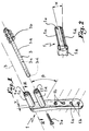
- Fig. 1 is a perspective view illustrating the plate which forms the device according to the present invention.
- Fig. 2 is a section along II-II (fig. 1) showing the offset towards the outside of the barrels.
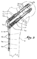
- Fig. 3 is a longitudinal section representing the positioning of the plate relative to the femur in order to repair the fracture of the femoral head.
- Fig. 4 and 5 are views illustrating a trochanteric hook which allows the improvement of the fixation of the plate in the femur.
- a device 1 for synthesis of fractures of the upper end of a femur 2 This device is provided for replacement of cephalic ball or femoral head 2 has on the body 2 of the femur.
- the device 1 comprises a plate 1 a , the profile of which is adapted to the external curvature of the femur 2.
- the lower part of the plate 1 a is pierced with several holes 1 b which allow its attachment to the femur 2.
- the upper part of the plate 1 a is formed in an arc relative to its lower portion so as to adapt perfectly to the external curvature of the femur 2 and more particularly below the greater trochanter.
- the side facing the top of the plate 1a is integral with two cylindrical barrels 1 c and 1 d of which the internal bore is smooth and slippery.
- Each barrel 1 c , 1 d is arranged so that its internal bore opens respectively into a stepped bore 1 e , 1 f formed in the upper part of the plate 1 a .
- the free end of each of the barrels 1 c and 1 d is chamfered and rounded to facilitate their positioning inside the holes which are previously drilled in the femur 2, as will be seen better below.
- Cannons 1 c and 1 d are provided parallel to each other and of lengths different.
- the barrel 1 d is provided with a length slightly greater than that of the barrel 1 c .
- the barrels 1 c and 1 d are offset towards the outside of the plate 1 a by an angle ⁇ either to the right or to the left depending on whether the stabilization relates to a right or left femur.
- the angle ⁇ is equal to approximately 13 ° relative to the vertical plane passing through the middle of the plate, so as to respond perfectly to the morphology of the femoral body.
- the barrels 1 c and 1 d are slightly offset from each other by a distance X to adapt to the torsion of the femoral neck, that is to say that the lower barrel 1 d is rather more posterior to the central axis of the plate 1 a , while the upper barrel 1 c is rather anterior to the same axis.
- the barrels 1 c and 1 d are inclined at an angle ⁇ relative to a horizontal axis passing through the middle of the plate 1 a .
- This angle ⁇ is equal to approximately 40 °.
- Each cephalic screw 3 comprises a cylindrical body 3 a whose outside diameter is adjusted relative to that of the bore of the barrels 1 c and 1 d so as to slide inside these.
- One of the ends of the cylindrical body 3 a comprises a thread 3 b with a conical and self-tapping profile which is anchored inside the cephalic ball 2 a .
- the internal part of the cylindrical body 3 a is pierced with a through hole 3 c , the end opposite to the thread 3 b is provided with a hexagonal bore 3 d allowing the screw 3 to be screwed in place of the cephalic ball 2 a .
- the hole 3 c is tapped to receive a screw 3 e .
- the plate 1 a is then fixed against the external profile of the femur 2 so that the barrels 1 c penetrate inside the latter by cooperating with the cephalic screws 3.
- a screw 3 e is screwed inside of each cephalic screw 3 in order to shoot it inside the barrels 1 c and 1 d .
- the establishment of the device 1 allows the cephalic ball 2 a to be pressed against the body of the femur 2 with a view to repairing the fracture.
- the element 4 has in its upper part a curved hook-shaped profile 4 a single or double depending on the conditions of use. Below the hook 4 a is provided a bearing face 4 b which is extended by two parallel branches 4 c . The branches 4 c are joined to each other in their lower part by a plate 4 d . The branches 4 c delimit a light 4 e which allows the positioning of the plate 1 a .
- the bearing face 4 b is pierced with two holes 4 f allowing the element 4 to be fixed in the upper part of the femur 2 and more particularly on the greater trochanter.
- the plate 4 d is pierced with several holes 4 g intersecting with each other to allow a screw to cooperate with the holes 1 b formed in the lower part of the plate 1 a .
- the element 4 has a profile adapted to the external curvature of the femur, and is mounted as a jumper on the plate 1 a .
- top of the plate 1 a is slightly collapsed so as not to come into conflict with the muscle attachments located at this location.
- the plate 1 a is made of a material such as stainless steel or any other bio-combatable material making it possible to ensure perfect function and security.
Abstract
Description
- La présente invention a trait à un dispositif pour la stabilisation des fractures de l'extrémité supérieure du fémur.
- On connaît des dispositifs de ce genre qui comprennent généralement une plaque qui est vissée dans la partie supérieure du fémur. Cette plaque comprend un canon lisse et cylindrique qui est introduit à l'intérieur d'un alésage préalablement ménagé dans la partie interne du fémur. Le canon permet la mise en place d'une vis de traction qui est mise sous tension pour rapprocher la boule céphalique du corps du fémur.
- Ce dispositif comporte une trop grande fragilité et une prise céphalique insuffisante entraînant des risques de rotation axiale de la boule céphalique ou tête fémorale. En outre, ces dispositifs exposent les patients à des risques de luxations, d'infections ou encore de cotyloïdites.
- C'est à ces inconvénients qu'entend plus particulièrement remédier la présente invention.
- Le dispositif suivant la présente invention a pour but d'améliorer l'ancrage entre la boule céphalique ou tête fémorale et le fémur en vue d'empêcher toute rotation de ladite boule par rapport au corps du fémur. De plus, la structure de ce dispositif permet la remise en charge rapide des patients, c'est-à-dire que ces derniers peuvent reprendre très vite la position verticale et la marche après l'opération.
- Le dispositif suivant la présente invention comprend une plaque qui est vissée dans le fémur et comportant dans sa partie supérieure deux canons parallèles et cylindriques qui sont décalés d'une part d'un angle α par rapport au plan vertical passant par le milieu de ladite plaque et d'autre part d'un angle β par rapport à l'axe horizontal passant par le milieu de la plaque.
- En outre, les canons sont décalés latéralement l'un par rapport à l'autre d'une distance X pour répondre parfaitement à la morphologie du fémur.
- Le dessin annexé, donné à titre d'exemple, permettra de mieux comprendre l'invention, les caractéristiques qu'elle présente et les avantages qu'elle est susceptible de procurer :
- Fig. 1 est une vue en perspective illustrant la plaque qui forme le dispositif suivant la présente invention.
- Fig. 2 est une coupe suivant II-II (fig. 1) montrant le décalage vers l'extérieur des canons.
- Fig. 3 est une coupe longitunale représentant la mise en place de la plaque par rapport au fémur en vue de réparer la fracture de la tête fémorale.
- Fig. 4 et 5 sont des vues illustrant un crochet trochantérien qui permet l'amélioration de la fixation de la plaque dans le fémur.
- On a représenté en fig. 1 à 3 un dispositif 1 de synthèse des fractures de l'extrémité supérieure d'un fémur 2. Ce dispositif est prévu pour la remise en place de la boule céphalique ou tête fémorale 2a sur le corps du fémur 2.
- Le dispositif 1 comprend une plaque 1a dont le profil est adapté à la courbure externe du fémur 2. La partie inférieure de la plaque 1a est percée de plusieurs trous 1b qui permettent sa fixation sur le fémur 2.
- La partie supérieure de la plaque 1a est conformée en arc de cercle par rapport à sa partie inférieure de manière à s'adapter parfaitement à la courbure externe du fémur 2 et plus particulièrement au dessous du grand trochanter.
- La face dirigée vers le haut de la plaque 1a est solidaire de deux canons cylindriques 1c et 1d dont l'alésage interne est lisse et glissant. Chaque canon 1c, 1d est disposé pour que son alésage interne débouche respectivement dans un alésage épaulé 1e, 1f ménagé dans la partie supérieure de la plaque 1a. L'extrémité libre de chacun des canons 1c et 1d est chamfreinée et arrondie pour faciliter leur mise en place à l'intérieur des trous qui sont préalablement percés dans le fémur 2, comme on le verra mieux plus loin.
- Les canons 1c et 1d sont prévus parallèles l'un à l'autre et de longueurs différentes. En effet, le canon 1d est prévu d'une longueur légèrement supérieure à celle du canon 1c.
- Les canons 1c et 1d sont décalés vers l'extérieur de la plaque 1a d'un angle α soit à droite, soit à gauche suivant que la stabilisation concerne un fémur droit ou gauche. L'angle α est égal à environ 13° par rapport au plan vertical passant par le milieu de la plaque, de manière à répondre parfaitement à la morphologie du corps fémoral.
- Les canons 1c et 1d sont légèrement décalés l'un par rapport à l'autre d'une distance X pour s'adapter à la torsion du col fémoral, c'est-à-dire que le canon inférieur 1d est plutôt plus postérieur par rapport à l'axe central de la plaque 1a, tandis que le canon supérieur 1c est plutôt antérieur par rapport au même axe.
- Les canons 1c et 1d sont inclinés d'un angle β par rapport à un axe horizontal passant par le milieu de la plaque 1a. Cet angle β est égal à environ 40°.
- La mise en place de la plaque 1a est classique, c'est-à-dire que l'on perce deux trous parallèles dans la partie supérieure du fémur 2 pour la mise en place de deux vis céphaliques 3. Chaque vis céphalique 3 comporte un corps cylindrique 3a dont le diamètre extérieur est ajusté par rapport à celui de l'alésage des canons 1c et 1d de manière à coulisser à l'intérieur de ceux-ci. L'une des extrémités du corps cylindrique 3a comprend un filet 3b à profil conique et auto-taraudant qui vient s'ancrer à l'intérieur de la boule céphalique 2a.
- La partie interne du corps cylindrique 3a est percée d'un trou débouchant 3c dont l'extrémité opposée au filet 3b est pourvue d'un alésage à six pans creux 3d permettant de visser en place la vis 3 à l'intérieur de la boule céphalique 2a.
- A proximité de l'alésage à six pans creux 3d, le trou 3c est taraudé pour recevoir une vis 3e.
- On fixe ensuite la plaque 1a contre le profil extérieur du fémur 2 de manière que les canons 1c pénètrent à l'intérieur de celui-ci en coopérant avec les vis céphaliques 3. Une vis 3e est vissée à l'intérieur de chaque vis céphalique 3 afin de tirer sur celle-ci à l'intérieur des canons 1c et 1d. La mise en place du dispositif 1 permet de plaquer la boule céphalique 2a contre le corps du fémur 2 en vue de la réparation de la fracture.
- On a représenté en fig. 4 et 5 un élément 4 qui permet la synthèse du massif du grand trochanter lorsque cela le nécessite en plus de la synthèse de la tête et du col du fémur.
- L'élément 4 présente dans sa partie supérieure un profil recourbé en forme de crochet 4a simple ou double suivant les conditions d'utilisation. En dessous du crochet 4a est prévue une face d'appui 4b qui se prolonge par deux branches parallèles 4c. Les branches 4c sont réunies l'une à l'autre dans leur partie inférieure par une plaque 4d. Les branches 4c délimitent une lumière 4e qui permet la mise en place de la plaque 1a.
- La face d'appui 4b est percée de deux trous 4f permettant la fixation de l'élément 4 dans la partie supérieure du fémur 2 et plus particulièrement sur le grand trochanter. La plaque 4d est percée de plusieurs trous 4g sécants les uns avec les autres pour permettre à une vis de coopérer avec les trous 1b ménagés dans la partie inférieure de la plaque 1a.
- L'élément 4 présente un profil adapté à la courbure externe du fémur, et vient se monter en cavalier sur la plaque 1a.
- On note que le sommet de la plaque 1a est légèrement affaissé pour ne pas entrer en conflit avec les attaches musculaires situées à cet endroit.
- On remarque de plus que plusieurs longueurs de plaques sont disponibles pour répondre à toutes les courbures anatomiques du fémur 2.
- On note également que la plaque 1a est réalisée en une matière telle que de l'acier inoxydable ou tout autre matériau bio-combatible permettant d'assurer une fonction et une sécurité parfaites.
Claims (7)
- Dispositif de synthèse des fractures de l'extrémité supérieure du fémur du genre comprenant une plaque qui est vissée dans le fémur et comportant un canon de glissement dans lequel est introduite une vis de mise en tension, caractérisé en ce que la plaque (1a) comporte dans sa partie supérieure deux canons (1c et 1d) parallèles et cylindriques qui sont décalés d'une part d'un angle α par rapport au plan vertical passant par le milieu de la plaque (1a) et d'autre part d'un angle β par rapport à un axe horizontal passant par le milieu de ladite plaque.
- Dispositif suivant la revendication 1, caractérisé en ce que les canons (1c et 1d) sont décalés latéralement l'un par rapport à l'autre d'une distance (X) pour répondre parfaitement à la morphologie du fémur (2).
- Dispositif suivant la revendication 1, caractérisé en ce que la partie supérieure de la plaque (1a) est conformée en arc-de-cercle de manière à s'adapter à la courbure externe du fémur (2).
- Dispositif suivant la revendication 1, caractérisé en ce que les canons (1c et 1d) comportent des alésages internes Lisses pour permettre le coulissement de vis d'ancrage (3) qui sont mises en traction à l'aide de vis (3e) pour plaquer la boule céphalique (2a) sur le fémur (2).
- Dispositif suivant la revendication 1, caractérisé en ce qu'un élément trochantérien (4) est associé au dispositif (1) par une synthèse complémentaire lors d'une fracture du massif trochantérien.
- Dispositif suivant la revendication 5, caractérisé en ce que l'élément (4) présente dans sa partie supérieure un profil recourbé en forme de crochet (4a) simple ou double en dessous duquel est prévue une face d'appui (4b) se prolongeant par deux branches parallèles (4c) qui sont réunies à leurs extrémités libres par une plaque (4d).
- Dispositif suivant la revendication 6, caractérisé en ce que la face d'appui (4a) comporte des trous (4f) pour la fixation de l'élément (4) dans la partie supérieure du fémur (2).
Applications Claiming Priority (2)
| Application Number | Priority Date | Filing Date | Title |
|---|---|---|---|
| FR9312899A FR2711505B1 (fr) | 1993-10-25 | 1993-10-25 | Dispositif de synthèse des fractures de l'extrémité supérieure du fémur. |
| FR9312899 | 1993-10-25 |
Publications (2)
| Publication Number | Publication Date |
|---|---|
| EP0649635A1 true EP0649635A1 (fr) | 1995-04-26 |
| EP0649635B1 EP0649635B1 (fr) | 2000-02-16 |
Family
ID=9452324
Family Applications (1)
| Application Number | Title | Priority Date | Filing Date |
|---|---|---|---|
| EP94420287A Expired - Lifetime EP0649635B1 (fr) | 1993-10-25 | 1994-10-24 | Dispositif de synthèse des fractures de l'extrémité supérieure du fémur |
Country Status (5)
| Country | Link |
|---|---|
| US (1) | US5591168A (fr) |
| EP (1) | EP0649635B1 (fr) |
| DE (1) | DE69423031T2 (fr) |
| ES (1) | ES2142392T3 (fr) |
| FR (1) | FR2711505B1 (fr) |
Cited By (15)
| Publication number | Priority date | Publication date | Assignee | Title |
|---|---|---|---|---|
| WO2001091660A1 (fr) | 2000-05-31 | 2001-12-06 | Vese, Silvana | Dispositif pour fixer des parties d'os separees en raison d'une fracture |
| US7229445B2 (en) | 2004-06-21 | 2007-06-12 | Synthes (Usa) | Bone plate with bladed portion |
| WO2008045278A1 (fr) * | 2006-10-04 | 2008-04-17 | Scott And White Memorial Hospital And Scott, Sherwood And Brindley Foundation | Fixation de fractures du col du fémur |
| US7951176B2 (en) | 2003-05-30 | 2011-05-31 | Synthes Usa, Llc | Bone plate |
| US10335211B2 (en) | 2004-01-26 | 2019-07-02 | DePuy Synthes Products, Inc. | Highly-versatile variable-angle bone plate system |
| US10342586B2 (en) | 2003-08-26 | 2019-07-09 | DePuy Synthes Products, Inc. | Bone plate |
| US10624686B2 (en) | 2016-09-08 | 2020-04-21 | DePuy Synthes Products, Inc. | Variable angel bone plate |
| US10772665B2 (en) | 2018-03-29 | 2020-09-15 | DePuy Synthes Products, Inc. | Locking structures for affixing bone anchors to a bone plate, and related systems and methods |
| US10820930B2 (en) | 2016-09-08 | 2020-11-03 | DePuy Synthes Products, Inc. | Variable angle bone plate |
| US10905476B2 (en) | 2016-09-08 | 2021-02-02 | DePuy Synthes Products, Inc. | Variable angle bone plate |
| US10925651B2 (en) | 2018-12-21 | 2021-02-23 | DePuy Synthes Products, Inc. | Implant having locking holes with collection cavity for shavings |
| US11013541B2 (en) | 2018-04-30 | 2021-05-25 | DePuy Synthes Products, Inc. | Threaded locking structures for affixing bone anchors to a bone plate, and related systems and methods |
| US11026727B2 (en) | 2018-03-20 | 2021-06-08 | DePuy Synthes Products, Inc. | Bone plate with form-fitting variable-angle locking hole |
| US11259851B2 (en) | 2003-08-26 | 2022-03-01 | DePuy Synthes Products, Inc. | Bone plate |
| US11291484B2 (en) | 2004-01-26 | 2022-04-05 | DePuy Synthes Products, Inc. | Highly-versatile variable-angle bone plate system |
Families Citing this family (165)
| Publication number | Priority date | Publication date | Assignee | Title |
|---|---|---|---|---|
| FR2719211B1 (fr) * | 1994-04-27 | 1996-07-19 | Mortier Jean Pierre | Matériel pour la correction de déformations du pied. |
| US5810823A (en) * | 1994-09-12 | 1998-09-22 | Synthes (U.S.A.) | Osteosynthetic bone plate and lock washer |
| US5976139A (en) | 1996-07-17 | 1999-11-02 | Bramlet; Dale G. | Surgical fastener assembly |
| EP0948293B1 (fr) | 1996-12-02 | 2002-09-25 | SYNTHES AG Chur | Clou intramedulaire plat |
| US5741256A (en) * | 1997-01-13 | 1998-04-21 | Synthes (U.S.A.) | Helical osteosynthetic implant |
| FR2768613B1 (fr) * | 1997-09-23 | 1999-12-17 | Tornier Sa | Prothese de genou a plateau rotatoire |
| DE29804268U1 (de) | 1998-03-11 | 1998-05-14 | Synthes Ag | Spiralklingen-Insertions-Instrument |
| US6183475B1 (en) * | 1998-12-18 | 2001-02-06 | Sulzer Orthopedics Inc. | Distal femoral osteotomy system and method |
| GR1003502B (el) * | 1999-04-26 | 2001-01-03 | Πλακα συγκρατησης καταγματων μειζονος τροχαντηρος | |
| FR2797178B1 (fr) * | 1999-08-05 | 2002-02-22 | Tornier Sa | Implant malleolaire pour prothese partielle ou totale de cheville et materiel ancillaire de pose d'un tel implant |
| FR2897259B1 (fr) | 2006-02-15 | 2008-05-09 | Ldr Medical Soc Par Actions Si | Cage intersomatique transforaminale a greffon de fusion intervetebrale et instrument d'implantation de la cage |
| EP1211992B1 (fr) * | 1999-09-13 | 2004-01-14 | Synthes AG Chur | Systeme de plaque vissee |
| FR2800268B1 (fr) * | 1999-10-29 | 2002-04-19 | Topline Technology Llc | Plaque orthopedique de suture et ancillaire pour la mise en place d'une telle plaque |
| AU774717B2 (en) | 1999-11-11 | 2004-07-08 | Synthes Gmbh | Radially expandable intramedullary nail |
| US6893444B2 (en) * | 2000-02-01 | 2005-05-17 | Hand Innovations, Llc | Bone fracture fixation systems with both multidirectional and unidirectional stabilization pegs |
| US6706046B2 (en) * | 2000-02-01 | 2004-03-16 | Hand Innovations, Inc. | Intramedullary fixation device for metaphyseal long bone fractures and methods of using the same |
| US20040153073A1 (en) * | 2000-02-01 | 2004-08-05 | Hand Innovations, Inc. | Orthopedic fixation system including plate element with threaded holes having divergent axes |
| US6767351B2 (en) * | 2000-02-01 | 2004-07-27 | Hand Innovations, Inc. | Fixation system with multidirectional stabilization pegs |
| US6730090B2 (en) | 2000-02-01 | 2004-05-04 | Hand Innovations, Inc. | Fixation device for metaphyseal long bone fractures |
| US7857838B2 (en) * | 2003-03-27 | 2010-12-28 | Depuy Products, Inc. | Anatomical distal radius fracture fixation plate |
| US7695502B2 (en) | 2000-02-01 | 2010-04-13 | Depuy Products, Inc. | Bone stabilization system including plate having fixed-angle holes together with unidirectional locking screws and surgeon-directed locking screws |
| US20060041260A1 (en) * | 2000-02-01 | 2006-02-23 | Orbay Jorge L | Fixation system with plate having holes with divergent axes and multidirectional fixators for use therethrough |
| US7207993B1 (en) * | 2000-02-03 | 2007-04-24 | Pioneer Laboratories, Inc. | Apparatus and method for repairing the femur |
| US7488329B2 (en) * | 2000-03-07 | 2009-02-10 | Zimmer Technology, Inc. | Method and apparatus for reducing femoral fractures |
| US7485119B2 (en) * | 2000-03-07 | 2009-02-03 | Zimmer Technology, Inc. | Method and apparatus for reducing femoral fractures |
| US7258692B2 (en) * | 2000-03-07 | 2007-08-21 | Zimmer, Inc. | Method and apparatus for reducing femoral fractures |
| US20030220646A1 (en) * | 2002-05-23 | 2003-11-27 | Thelen Sarah L. | Method and apparatus for reducing femoral fractures |
| US20030220644A1 (en) * | 2002-05-23 | 2003-11-27 | Thelen Sarah L. | Method and apparatus for reducing femoral fractures |
| US6409730B1 (en) | 2000-05-31 | 2002-06-25 | Synthes (Usa) | Humeral spiral blade |
| US6447546B1 (en) | 2000-08-11 | 2002-09-10 | Dale G. Bramlet | Apparatus and method for fusing opposing spinal vertebrae |
| DE10107369B4 (de) * | 2001-02-16 | 2016-03-24 | Ernst Wiedemann | Implantatplatte |
| US6887243B2 (en) * | 2001-03-30 | 2005-05-03 | Triage Medical, Inc. | Method and apparatus for bone fixation with secondary compression |
| US6511481B2 (en) | 2001-03-30 | 2003-01-28 | Triage Medical, Inc. | Method and apparatus for fixation of proximal femoral fractures |
| US20020156474A1 (en) * | 2001-04-20 | 2002-10-24 | Michael Wack | Polyaxial locking plate |
| FR2824261B1 (fr) | 2001-05-04 | 2004-05-28 | Ldr Medical | Prothese de disque intervertebral et procede et outils de mise en place |
| PT1389963E (pt) | 2001-05-28 | 2006-10-31 | Synthes Ag | Placa de osso para a fixacao de fracturas do umero proximal |
| FR2826859B1 (fr) * | 2001-07-09 | 2003-09-19 | Tornier Sa | Ancillaire de pose d'un composant humeral de prothese de coude |
| FR2826860B1 (fr) * | 2001-07-09 | 2004-03-05 | Tornier Sa | Ancillaire de pose d'un composant cubital et/ou d'un composant radial de prothese de coude |
| FR2827156B1 (fr) | 2001-07-13 | 2003-11-14 | Ldr Medical | Dispositif de cage vertebrale avec fixation modulaire |
| FR2827500B1 (fr) * | 2001-07-17 | 2004-04-02 | Tornier Sa | Plaque d'osteosynthese de l'extremite superieure de l'humerus |
| US20030055316A1 (en) * | 2001-09-19 | 2003-03-20 | Brannon James Kevin | Endoscopic bone debridement |
| US6607561B2 (en) * | 2001-10-02 | 2003-08-19 | James Kevin Brannon | Biaxial core compression |
| US6835197B2 (en) | 2001-10-17 | 2004-12-28 | Christoph Andreas Roth | Bone fixation system |
| US8828067B2 (en) * | 2001-10-18 | 2014-09-09 | Orthoip, Llc | Bone screw system and method |
| US7938850B2 (en) * | 2002-05-30 | 2011-05-10 | Depuy Products, Inc. | Nail plate |
| US20060149257A1 (en) * | 2002-05-30 | 2006-07-06 | Orbay Jorge L | Fracture fixation device |
| DE20208922U1 (de) * | 2002-06-05 | 2003-10-09 | Stryker Trauma Gmbh | Schenkelhalsschraube |
| US6793678B2 (en) | 2002-06-27 | 2004-09-21 | Depuy Acromed, Inc. | Prosthetic intervertebral motion disc having dampening |
| WO2004008949A2 (fr) * | 2002-07-19 | 2004-01-29 | Triage Medical, Inc. | Procede et appareil de fixation vertebrale |
| US20040111090A1 (en) * | 2002-10-03 | 2004-06-10 | The University Of North Carolina At Chapel Hill | Modification of percutaneous intrafocal plate system |
| FR2846550B1 (fr) | 2002-11-05 | 2006-01-13 | Ldr Medical | Prothese de disque intervertebral |
| US20050187551A1 (en) * | 2002-12-02 | 2005-08-25 | Orbay Jorge L. | Bone plate system with bone screws fixed by secondary compression |
| US7780664B2 (en) | 2002-12-10 | 2010-08-24 | Depuy Products, Inc. | Endosteal nail |
| FR2848183B1 (fr) * | 2002-12-10 | 2006-01-27 | Tornier Sa | Procede de conditionnement sterile d'un implant prothetique en polyethylene |
| US7070601B2 (en) * | 2003-01-16 | 2006-07-04 | Triage Medical, Inc. | Locking plate for bone anchors |
| FR2850010B1 (fr) * | 2003-01-17 | 2005-12-02 | Tornier Sa | Ancillaire de pose d'un cotyle prothetique pour une prothese de hanche |
| US20060052788A1 (en) * | 2003-02-04 | 2006-03-09 | Thelen Sarah L | Expandable fixation devices for minimally invasive surgery |
| ITTO20030034U1 (it) * | 2003-02-28 | 2004-09-01 | Vese Silvana | Placca di osteosintesi |
| EP2263584B1 (fr) * | 2003-03-07 | 2012-09-05 | Synthes GmbH | Clou intramédullaire avec vis de blocage |
| US7887544B2 (en) | 2003-03-10 | 2011-02-15 | Tornier Sas | Ancillary tool for positioning a glenoid implant |
| CN100374093C (zh) * | 2003-03-13 | 2008-03-12 | 钱本文 | 无柄人工髋关节装置 |
| US20040193155A1 (en) * | 2003-03-27 | 2004-09-30 | Hand Innovations, Inc. | Fracture fixation plate with particular plate hole and fastener engagement and methods of using the same |
| FR2854792B1 (fr) * | 2003-05-12 | 2005-09-09 | Tornier Sa | Jeu d'elements prothetiques pour un ensemble prothetique tibial |
| FR2855397B1 (fr) | 2003-05-28 | 2005-07-15 | Tornier Sa | Prothese de coude |
| BR0318327B1 (pt) * | 2003-06-12 | 2013-06-18 | garra cirérgica. | |
| ATE476148T1 (de) * | 2003-06-12 | 2010-08-15 | Synthes Gmbh | Chirurgischer nagel |
| WO2005009263A1 (fr) * | 2003-07-30 | 2005-02-03 | Synthes Ag Chur | Clou chirurgical |
| WO2005020830A1 (fr) | 2003-08-29 | 2005-03-10 | Synthes Gmbh | Clou intramedullaire |
| US7780667B2 (en) * | 2003-09-08 | 2010-08-24 | Smith & Nephew, Inc. | Orthopaedic plate and screw assembly |
| JP2007506452A (ja) * | 2003-09-08 | 2007-03-22 | ジンテーズ アクチエンゲゼルシャフト クール | 骨固定装置 |
| US7799030B2 (en) * | 2003-09-08 | 2010-09-21 | Smith & Nephew, Inc. | Orthopaedic plate and screw assembly |
| US20050055024A1 (en) * | 2003-09-08 | 2005-03-10 | James Anthony H. | Orthopaedic implant and screw assembly |
| US8105367B2 (en) * | 2003-09-29 | 2012-01-31 | Smith & Nephew, Inc. | Bone plate and bone plate assemblies including polyaxial fasteners |
| NZ546545A (en) * | 2003-10-21 | 2008-11-28 | Synthes Gmbh | Intramedullary nail |
| EP1677693B1 (fr) * | 2003-10-30 | 2009-04-15 | Synthes GmbH | Plaque d'osteosynthese |
| FR2863865B1 (fr) | 2003-12-19 | 2006-10-06 | Tornier Sa | Prothese d'epaule ou de hanche et son procede de montage |
| US7637928B2 (en) * | 2004-01-26 | 2009-12-29 | Synthes Usa, Llc | Variable angle locked bone fixation system |
| FR2865629B1 (fr) * | 2004-02-04 | 2007-01-26 | Ldr Medical | Prothese de disque intervertebral |
| ES2363154T3 (es) | 2004-02-04 | 2011-07-22 | Ldr Medical | Prótesis de disco intervertebral. |
| FR2865928B1 (fr) | 2004-02-10 | 2006-03-17 | Tornier Sa | Dispositif chirurgical d'implantation d'une prothese totale de hanche |
| US8734448B2 (en) * | 2004-04-12 | 2014-05-27 | Navin N Thakkar | Implant assembly for proximal femoral fracture |
| FR2869528B1 (fr) | 2004-04-28 | 2007-02-02 | Ldr Medical | Prothese de disque intervertebral |
| US8303665B2 (en) | 2004-06-15 | 2012-11-06 | Tornier Sas | Glenoidal component, set of such components and shoulder prosthesis incorporating such a glenoidal component |
| US7678150B2 (en) * | 2004-06-15 | 2010-03-16 | Tornier Sas | Total shoulder prosthesis of an inverted type |
| FR2871368B1 (fr) * | 2004-06-15 | 2006-08-25 | Tornier Sas | Jeu de composants humeraux pour prothese totale d'epaule |
| FR2871371B1 (fr) | 2004-06-15 | 2007-04-06 | Tornier Sas | Composant glenoidien de prothese d'epaule, jeu d'elements constitutifs d'un tel composant et prothese totale d'epaule incorporant un tel composant |
| CA2571469C (fr) * | 2004-06-22 | 2012-09-25 | Synthes (U.S.A.) | Clou intramedullaire |
| CA2571672C (fr) * | 2004-06-24 | 2012-08-28 | Synthes (U.S.A.) | Clou d'osteosynthese intramedullaire |
| FR2872025B1 (fr) * | 2004-06-28 | 2006-08-25 | Tornier Sas | Prothese d'epaule ou de hanche |
| EP1761182B1 (fr) * | 2004-06-30 | 2011-04-06 | Synthes GmbH | Clou chirurgical |
| WO2006023793A2 (fr) * | 2004-08-20 | 2006-03-02 | Triage Medical, Inc. | Procede et appareil d'administration d'un agent |
| FR2879436B1 (fr) | 2004-12-22 | 2007-03-09 | Ldr Medical | Prothese de disque intervertebral |
| EP1855605B1 (fr) * | 2005-01-28 | 2014-01-08 | Biomet C.V. | Systeme clou-plaque |
| FR2881340B1 (fr) * | 2005-02-01 | 2008-01-11 | Tornier Sas | Clou humeral |
| FR2884407B1 (fr) * | 2005-04-13 | 2007-05-25 | Tornier Sas | Dispositif chirurgical d'implantation d'une prothese partielle ou totale du genou |
| FR2884408B1 (fr) * | 2005-04-13 | 2007-05-25 | Tornier Sas | Dispositif chirurgical d'implantation d'une prothese partielle ou totale de genou |
| US8382807B2 (en) | 2005-07-25 | 2013-02-26 | Smith & Nephew, Inc. | Systems and methods for using polyaxial plates |
| CN101272743B (zh) | 2005-07-25 | 2011-01-26 | 史密夫和内修有限公司 | 使用多轴式板的系统 |
| US7468077B2 (en) * | 2005-08-02 | 2008-12-23 | Tornier Sas | Patellar retractor and method of surgical procedure on knee |
| US7905909B2 (en) * | 2005-09-19 | 2011-03-15 | Depuy Products, Inc. | Bone stabilization system including multi-directional threaded fixation element |
| FR2891135B1 (fr) | 2005-09-23 | 2008-09-12 | Ldr Medical Sarl | Prothese de disque intervertebral |
| FR2893838B1 (fr) | 2005-11-30 | 2008-08-08 | Ldr Medical Soc Par Actions Si | Prothese de disque intervertebral et instrumentation d'insertion de la prothese entre les vertebres |
| FR2896404B1 (fr) | 2006-01-24 | 2008-02-29 | Tornier Sas | Ensemble d'instrumentation chirurgicale pour poser une prothese de cheville |
| FR2896684B1 (fr) * | 2006-02-01 | 2008-09-26 | Tornier Soc Par Actions Simplifiee | Implant tibial a tige offset |
| US20070225715A1 (en) * | 2006-03-24 | 2007-09-27 | Depuy Products, Inc. | Fastening system for internal fixation |
| FR2899790B1 (fr) | 2006-04-13 | 2008-06-13 | Tornier Sas | Composant glenoidien pour prothese totale d'epaule, jeu de tels composants, et prothese totale d'epaule comprenant un tel composant |
| FR2900045B1 (fr) * | 2006-04-21 | 2009-01-16 | Tornier Sas | Prothese d'epaule ou de hanche |
| WO2008038286A1 (fr) * | 2006-09-28 | 2008-04-03 | Ogen Innovative Medical Devices Ltd. | Fixation osseuse orthopédique |
| FR2906999B1 (fr) | 2006-10-13 | 2009-06-05 | Tornier Sas | Ensemble prothetique de cheville |
| WO2008070863A2 (fr) | 2006-12-07 | 2008-06-12 | Interventional Spine, Inc. | Implant intervertébral |
| IL181211A0 (en) * | 2007-02-07 | 2007-07-04 | Nmb Medical Applic Ltd | Device and methods for strengthening long bones |
| US8465546B2 (en) | 2007-02-16 | 2013-06-18 | Ldr Medical | Intervertebral disc prosthesis insertion assemblies |
| US7722611B2 (en) * | 2007-03-05 | 2010-05-25 | Depuy Products, Inc. | Method of treating a clavicle fracture |
| US7918853B2 (en) * | 2007-03-20 | 2011-04-05 | Smith & Nephew, Inc. | Orthopaedic plate and screw assembly |
| FR2916956B1 (fr) | 2007-06-08 | 2012-12-14 | Ldr Medical | Cage intersomatique,prothese intervertebrale,dispositif d'ancrage et instrumentation d'implantation |
| US8900307B2 (en) | 2007-06-26 | 2014-12-02 | DePuy Synthes Products, LLC | Highly lordosed fusion cage |
| SE533303C2 (sv) * | 2007-07-24 | 2010-08-17 | Henrik Hansson | Anordning för fixering av benfragment vid benbrott |
| SE533302C2 (sv) * | 2007-07-24 | 2010-08-17 | Henrik Hansson | Anordning för fixering av benfragment vid benbrott |
| ES2424446T3 (es) * | 2007-11-13 | 2013-10-02 | Synthes Gmbh | Reparación de una fractura periprotésica |
| JP5441922B2 (ja) | 2008-01-17 | 2014-03-12 | ジンテス ゲゼルシャフト ミット ベシュレンクテル ハフツング | 膨張可能な椎間インプラント及び関連するその製造方法 |
| EP2262449B1 (fr) | 2008-04-05 | 2020-03-11 | Synthes GmbH | Implant intervertébral extensible |
| WO2010061410A1 (fr) * | 2008-11-25 | 2010-06-03 | Intrauma S.R.L | Plaque modulaire d'ostéosynthèse à crochet |
| ITTO20090188A1 (it) * | 2009-03-12 | 2010-09-13 | Intrauma S R L | Dispositivo di osteosintesi per fratture femorali. |
| WO2010103494A2 (fr) * | 2009-03-12 | 2010-09-16 | Intrauma S.R.L. | Plaque d'ostéosynthèse pour fractures du fémur |
| US9526620B2 (en) | 2009-03-30 | 2016-12-27 | DePuy Synthes Products, Inc. | Zero profile spinal fusion cage |
| US20100331891A1 (en) * | 2009-06-24 | 2010-12-30 | Interventional Spine, Inc. | System and method for spinal fixation |
| BRPI1011556A2 (pt) | 2009-06-30 | 2016-03-29 | Smith & Nephew Inc | implante ortopédico e montagem de fixação |
| US8449544B2 (en) | 2009-06-30 | 2013-05-28 | Smith & Nephew, Inc. | Orthopaedic implant and fastener assembly |
| EP2477566B1 (fr) * | 2009-09-14 | 2017-03-22 | Synthes GmbH | Plaque de compression à angle variable |
| BR112012005663A2 (pt) | 2009-09-17 | 2021-07-27 | Synthes Gmbh | implante intervertebral com membros de fixação óssea expansíveis |
| US9393129B2 (en) | 2009-12-10 | 2016-07-19 | DePuy Synthes Products, Inc. | Bellows-like expandable interbody fusion cage |
| CA2688903C (fr) * | 2009-12-18 | 2017-08-29 | Shahryar Ahmadi | Systeme de fixation des os |
| CN102781373B (zh) | 2009-12-31 | 2016-10-26 | Ldr医疗公司 | 锚定装置、椎间植入物和植入器械 |
| US8979860B2 (en) | 2010-06-24 | 2015-03-17 | DePuy Synthes Products. LLC | Enhanced cage insertion device |
| US8845733B2 (en) | 2010-06-24 | 2014-09-30 | DePuy Synthes Products, LLC | Lateral spondylolisthesis reduction cage |
| TW201215379A (en) | 2010-06-29 | 2012-04-16 | Synthes Gmbh | Distractible intervertebral implant |
| US9402732B2 (en) | 2010-10-11 | 2016-08-02 | DePuy Synthes Products, Inc. | Expandable interspinous process spacer implant |
| US8518042B2 (en) * | 2010-10-19 | 2013-08-27 | Biomet Manufacturing, Llc | Orthopedic plate assembly for a distal radius having re-contouring features and method for using same |
| FR2966343B1 (fr) | 2010-10-22 | 2012-12-07 | Tornier Sa | Jeu de composants glenoidiens d'une prothese d'epaule |
| BR112013032140A2 (pt) | 2011-06-15 | 2016-12-13 | Smith & Nephew Inc | implante de travamento de ângulo variável |
| CN104114113B (zh) | 2011-11-18 | 2018-02-06 | 新特斯有限责任公司 | 股骨颈骨折植入物 |
| EP2626020B1 (fr) | 2012-02-13 | 2014-04-02 | Stryker Trauma SA | Dispositif de fixation pour plaque d'os |
| FR2987256B1 (fr) | 2012-02-24 | 2014-08-08 | Ldr Medical | Dispositif d'ancrage pour implant intervertebral, implant intervertebral et instrumentation d'implantation |
| EP2877127B1 (fr) | 2012-07-26 | 2019-08-21 | Synthes GmbH | Implant expansible |
| US20140031934A1 (en) * | 2012-07-26 | 2014-01-30 | Warsaw Orthopedic, Inc. | Sacro-iliac joint implant system and method |
| US20140067069A1 (en) | 2012-08-30 | 2014-03-06 | Interventional Spine, Inc. | Artificial disc |
| US9522070B2 (en) | 2013-03-07 | 2016-12-20 | Interventional Spine, Inc. | Intervertebral implant |
| US9522028B2 (en) | 2013-07-03 | 2016-12-20 | Interventional Spine, Inc. | Method and apparatus for sacroiliac joint fixation |
| US9681960B2 (en) | 2014-05-16 | 2017-06-20 | Howmedica Osteonics Corp. | Guides for fracture system |
| US10575968B2 (en) | 2014-05-16 | 2020-03-03 | Howmedica Osteonics Corp. | Guides for fracture system |
| US11426290B2 (en) | 2015-03-06 | 2022-08-30 | DePuy Synthes Products, Inc. | Expandable intervertebral implant, system, kit and method |
| US9913727B2 (en) | 2015-07-02 | 2018-03-13 | Medos International Sarl | Expandable implant |
| GB2557840B (en) | 2015-09-18 | 2021-07-21 | Smith & Nephew Inc | Bone plate |
| CN105596069B (zh) * | 2016-02-17 | 2019-07-26 | 陆海波 | 一种治疗股骨颈骨折的内固定装置 |
| WO2018002715A2 (fr) | 2016-06-28 | 2018-01-04 | Eit Emerging Implant Technologies Gmbh | Cages intervertébrales articulées à expansion et réglage angulaire |
| WO2018002711A2 (fr) | 2016-06-28 | 2018-01-04 | Eit Emerging Implant Technologies Gmbh | Cages intervertébrales à expansion et réglage angulaire |
| US10537436B2 (en) | 2016-11-01 | 2020-01-21 | DePuy Synthes Products, Inc. | Curved expandable cage |
| US10888433B2 (en) | 2016-12-14 | 2021-01-12 | DePuy Synthes Products, Inc. | Intervertebral implant inserter and related methods |
| US10398563B2 (en) | 2017-05-08 | 2019-09-03 | Medos International Sarl | Expandable cage |
| US11344424B2 (en) | 2017-06-14 | 2022-05-31 | Medos International Sarl | Expandable intervertebral implant and related methods |
| US10940016B2 (en) | 2017-07-05 | 2021-03-09 | Medos International Sarl | Expandable intervertebral fusion cage |
| US11446156B2 (en) | 2018-10-25 | 2022-09-20 | Medos International Sarl | Expandable intervertebral implant, inserter instrument, and related methods |
| US11426286B2 (en) | 2020-03-06 | 2022-08-30 | Eit Emerging Implant Technologies Gmbh | Expandable intervertebral implant |
| US11850160B2 (en) | 2021-03-26 | 2023-12-26 | Medos International Sarl | Expandable lordotic intervertebral fusion cage |
| US11752009B2 (en) | 2021-04-06 | 2023-09-12 | Medos International Sarl | Expandable intervertebral fusion cage |
Citations (6)
| Publication number | Priority date | Publication date | Assignee | Title |
|---|---|---|---|---|
| US2772676A (en) * | 1951-12-06 | 1956-12-04 | Pohl Ernst | Connecting device for bone fractures in the neighborhood of joints |
| US3824995A (en) * | 1972-07-24 | 1974-07-23 | Villiers E | Trochanteric plate |
| FR2289154A1 (fr) * | 1974-10-31 | 1976-05-28 | Tornier Rene | Perfectionnements aux dispositifs permettant les osteosyntheses cervicales du femur |
| WO1981002388A1 (fr) * | 1980-02-19 | 1981-09-03 | Mecron Med Prod Gmbh | Dispositif de fixation d'un col de femur au corps d'un femur |
| EP0515828A1 (fr) * | 1991-05-30 | 1992-12-02 | Synthes AG, Chur | Dispositif de stabilisation du trochanter |
| DE9303830U1 (fr) * | 1993-03-11 | 1993-06-09 | Aap Gmbh & Co. Betriebs Kg, 1000 Berlin, De |
Family Cites Families (6)
| Publication number | Priority date | Publication date | Assignee | Title |
|---|---|---|---|---|
| DE303830C (fr) * | ||||
| US3489143A (en) * | 1967-12-15 | 1970-01-13 | William X Halloran | Convertible hip pin |
| US3554193A (en) * | 1968-07-05 | 1971-01-12 | Ilias Konstantinou | Femur-setting surgical device |
| FR2045724A1 (fr) * | 1969-06-27 | 1971-03-05 | Bindschedler Pierre | |
| DE8900121U1 (fr) * | 1989-01-04 | 1990-02-15 | Mecron Medizinische Produkte Gmbh, 1000 Berlin, De | |
| IT1232572B (it) * | 1989-02-10 | 1992-02-26 | Calderale Pasquale Mario | Mezzi di osteosintesi per il collegamento di segmenti di fratture ossee |
-
1993
- 1993-10-25 FR FR9312899A patent/FR2711505B1/fr not_active Expired - Fee Related
-
1994
- 1994-10-24 EP EP94420287A patent/EP0649635B1/fr not_active Expired - Lifetime
- 1994-10-24 ES ES94420287T patent/ES2142392T3/es not_active Expired - Lifetime
- 1994-10-24 DE DE69423031T patent/DE69423031T2/de not_active Expired - Lifetime
-
1996
- 1996-05-07 US US08/643,835 patent/US5591168A/en not_active Expired - Fee Related
Patent Citations (6)
| Publication number | Priority date | Publication date | Assignee | Title |
|---|---|---|---|---|
| US2772676A (en) * | 1951-12-06 | 1956-12-04 | Pohl Ernst | Connecting device for bone fractures in the neighborhood of joints |
| US3824995A (en) * | 1972-07-24 | 1974-07-23 | Villiers E | Trochanteric plate |
| FR2289154A1 (fr) * | 1974-10-31 | 1976-05-28 | Tornier Rene | Perfectionnements aux dispositifs permettant les osteosyntheses cervicales du femur |
| WO1981002388A1 (fr) * | 1980-02-19 | 1981-09-03 | Mecron Med Prod Gmbh | Dispositif de fixation d'un col de femur au corps d'un femur |
| EP0515828A1 (fr) * | 1991-05-30 | 1992-12-02 | Synthes AG, Chur | Dispositif de stabilisation du trochanter |
| DE9303830U1 (fr) * | 1993-03-11 | 1993-06-09 | Aap Gmbh & Co. Betriebs Kg, 1000 Berlin, De |
Cited By (21)
| Publication number | Priority date | Publication date | Assignee | Title |
|---|---|---|---|---|
| WO2001091660A1 (fr) | 2000-05-31 | 2001-12-06 | Vese, Silvana | Dispositif pour fixer des parties d'os separees en raison d'une fracture |
| US6902567B2 (en) | 2000-05-31 | 2005-06-07 | Silvana Vese | Device for fixing bone sections separated because of a fracture |
| US10653466B2 (en) | 2003-05-30 | 2020-05-19 | DePuy Synthes Products, Inc. | Bone plate |
| US11419647B2 (en) | 2003-05-30 | 2022-08-23 | DePuy Synthes Products, Inc. | Bone plate |
| US7951176B2 (en) | 2003-05-30 | 2011-05-31 | Synthes Usa, Llc | Bone plate |
| US9931148B2 (en) | 2003-05-30 | 2018-04-03 | DePuy Synthes Products, Inc. | Bone plate |
| US10231768B2 (en) | 2003-05-30 | 2019-03-19 | DePuy Synthes Products, Inc. | Methods for implanting bone plates |
| US10342586B2 (en) | 2003-08-26 | 2019-07-09 | DePuy Synthes Products, Inc. | Bone plate |
| US11259851B2 (en) | 2003-08-26 | 2022-03-01 | DePuy Synthes Products, Inc. | Bone plate |
| US10335211B2 (en) | 2004-01-26 | 2019-07-02 | DePuy Synthes Products, Inc. | Highly-versatile variable-angle bone plate system |
| US11291484B2 (en) | 2004-01-26 | 2022-04-05 | DePuy Synthes Products, Inc. | Highly-versatile variable-angle bone plate system |
| US7229445B2 (en) | 2004-06-21 | 2007-06-12 | Synthes (Usa) | Bone plate with bladed portion |
| WO2008045278A1 (fr) * | 2006-10-04 | 2008-04-17 | Scott And White Memorial Hospital And Scott, Sherwood And Brindley Foundation | Fixation de fractures du col du fémur |
| US10624686B2 (en) | 2016-09-08 | 2020-04-21 | DePuy Synthes Products, Inc. | Variable angel bone plate |
| US11529176B2 (en) | 2016-09-08 | 2022-12-20 | DePuy Synthes Products, Inc. | Variable angle bone plate |
| US10905476B2 (en) | 2016-09-08 | 2021-02-02 | DePuy Synthes Products, Inc. | Variable angle bone plate |
| US10820930B2 (en) | 2016-09-08 | 2020-11-03 | DePuy Synthes Products, Inc. | Variable angle bone plate |
| US11026727B2 (en) | 2018-03-20 | 2021-06-08 | DePuy Synthes Products, Inc. | Bone plate with form-fitting variable-angle locking hole |
| US10772665B2 (en) | 2018-03-29 | 2020-09-15 | DePuy Synthes Products, Inc. | Locking structures for affixing bone anchors to a bone plate, and related systems and methods |
| US11013541B2 (en) | 2018-04-30 | 2021-05-25 | DePuy Synthes Products, Inc. | Threaded locking structures for affixing bone anchors to a bone plate, and related systems and methods |
| US10925651B2 (en) | 2018-12-21 | 2021-02-23 | DePuy Synthes Products, Inc. | Implant having locking holes with collection cavity for shavings |
Also Published As
| Publication number | Publication date |
|---|---|
| FR2711505B1 (fr) | 1995-12-29 |
| FR2711505A1 (fr) | 1995-05-05 |
| US5591168A (en) | 1997-01-07 |
| EP0649635B1 (fr) | 2000-02-16 |
| DE69423031T2 (de) | 2000-08-03 |
| DE69423031D1 (de) | 2000-03-23 |
| ES2142392T3 (es) | 2000-04-16 |
Similar Documents
| Publication | Publication Date | Title |
|---|---|---|
| EP0649635B1 (fr) | Dispositif de synthèse des fractures de l'extrémité supérieure du fémur | |
| EP1926444B2 (fr) | Systeme de fixation vertebrale | |
| EP1123056B1 (fr) | Plaque anterieure pour vertebres lombaires et instrument pour son positionnement | |
| EP0599752B1 (fr) | Dispositif d'ostéosynthèse pour fractures trochantérienne ou trochantéro-diaphysaire | |
| EP0392927B1 (fr) | Implant vertébral pour dispositif d'ostéosynthèse | |
| EP1933743B1 (fr) | Ancillaire de mise en tension d'un lien souple | |
| EP0641548B1 (fr) | Vis pour fixateur lombo-sacre | |
| EP0578807A1 (fr) | Ensemble d'implants d'osteosynthese et son dispositif de pose | |
| FR2777447A1 (fr) | Dispositif de fixation reversible pour la mise en place d'un implant dans l'os | |
| WO2005023126A1 (fr) | Implant rachidien | |
| WO2002045607A1 (fr) | Dispositif de fixation d'une tige et d'une tete de vis a symetrie spherique | |
| FR2680461A1 (fr) | Implant pour dispositif d'osteosynthese notamment du rachis et dispositif correspondant pour sa mise en place. | |
| FR2718945A1 (fr) | Dispositif de retenue d'une tige de liaison d'un fixateur de rachis sur une vis pédiculaire. | |
| FR2831420A1 (fr) | Appareil de maintien du rachis a assemblage par coincement | |
| FR2790941A1 (fr) | Instrumentation d'osteosynthese rachidienne a plaque et vis pediculaire ou a connecteur transversal entre une tige vertebrale et une vis pediculaire | |
| FR2683715A1 (fr) | Prothese textile de ligament croise anterieur du genou. | |
| CH661185A5 (en) | Watch bracelet | |
| FR2712173A1 (fr) | Dispositif pour la réduction de fractures. | |
| FR2736818A1 (fr) | Prothese pour articulation permettant une flexion avec une certaine laxite laterale | |
| FR2951064A1 (fr) | Plaque pour dispositif d'osteosynthese rachidienne par voie anterieure | |
| FR3004636A1 (fr) | Ensemble de reprise pour materiel d'osteosynthese vertebrale | |
| FR2873913A1 (fr) | Ensemble de fixation intramedullaire pour tete femorale | |
| FR2740674A1 (fr) | Dispositif de fixation d'une tige au sacrum en osteosynthese du rachis | |
| FR3089110A1 (fr) | Dispositif de redressement et de stabilisation d'une colonne vertébrale | |
| WO1996031167A1 (fr) | Dispositif pour le redressement et l'etaiement d'un rachis |
Legal Events
| Date | Code | Title | Description |
|---|---|---|---|
| PUAI | Public reference made under article 153(3) epc to a published international application that has entered the european phase |
Free format text: ORIGINAL CODE: 0009012 |
|
| AK | Designated contracting states |
Kind code of ref document: A1 Designated state(s): BE CH DE ES FR GB IT LI NL |
|
| 17P | Request for examination filed |
Effective date: 19950602 |
|
| 17Q | First examination report despatched |
Effective date: 19990203 |
|
| GRAG | Despatch of communication of intention to grant |
Free format text: ORIGINAL CODE: EPIDOS AGRA |
|
| GRAG | Despatch of communication of intention to grant |
Free format text: ORIGINAL CODE: EPIDOS AGRA |
|
| GRAH | Despatch of communication of intention to grant a patent |
Free format text: ORIGINAL CODE: EPIDOS IGRA |
|
| RAP1 | Party data changed (applicant data changed or rights of an application transferred) |
Owner name: TORNIER S.A. |
|
| RTI1 | Title (correction) |
Free format text: DEVICE FOR JOINING TOGETHER FRACTURES OF THE UPPER EXTREMITY OF THE FEMUR |
|
| RAP1 | Party data changed (applicant data changed or rights of an application transferred) |
Owner name: TORNIER SA |
|
| GRAH | Despatch of communication of intention to grant a patent |
Free format text: ORIGINAL CODE: EPIDOS IGRA |
|
| GRAA | (expected) grant |
Free format text: ORIGINAL CODE: 0009210 |
|
| AK | Designated contracting states |
Kind code of ref document: B1 Designated state(s): BE CH DE ES FR GB IT LI NL |
|
| REG | Reference to a national code |
Ref country code: CH Ref legal event code: EP |
|
| REF | Corresponds to: |
Ref document number: 69423031 Country of ref document: DE Date of ref document: 20000323 |
|
| REG | Reference to a national code |
Ref country code: ES Ref legal event code: FG2A Ref document number: 2142392 Country of ref document: ES Kind code of ref document: T3 |
|
| GBT | Gb: translation of ep patent filed (gb section 77(6)(a)/1977) |
Effective date: 20000329 |
|
| ITF | It: translation for a ep patent filed |
Owner name: SOCIETA' ITALIANA BREVETTI S.P.A. |
|
| EN | Fr: translation not filed | ||
| PG25 | Lapsed in a contracting state [announced via postgrant information from national office to epo] |
Ref country code: FR Free format text: LAPSE BECAUSE OF FAILURE TO SUBMIT A TRANSLATION OF THE DESCRIPTION OR TO PAY THE FEE WITHIN THE PRESCRIBED TIME-LIMIT Effective date: 20000713 |
|
| EN4 | Fr: notification of non filing translation in an earlier bopi is erroneous | ||
| PLBE | No opposition filed within time limit |
Free format text: ORIGINAL CODE: 0009261 |
|
| STAA | Information on the status of an ep patent application or granted ep patent |
Free format text: STATUS: NO OPPOSITION FILED WITHIN TIME LIMIT |
|
| 26N | No opposition filed | ||
| REG | Reference to a national code |
Ref country code: GB Ref legal event code: IF02 |
|
| PGFP | Annual fee paid to national office [announced via postgrant information from national office to epo] |
Ref country code: NL Payment date: 20070618 Year of fee payment: 14 |
|
| PGFP | Annual fee paid to national office [announced via postgrant information from national office to epo] |
Ref country code: BE Payment date: 20071105 Year of fee payment: 14 |
|
| PGFP | Annual fee paid to national office [announced via postgrant information from national office to epo] |
Ref country code: GB Payment date: 20071016 Year of fee payment: 14 |
|
| BERE | Be: lapsed |
Owner name: S.A. *TORNIER Effective date: 20081031 |
|
| GBPC | Gb: european patent ceased through non-payment of renewal fee |
Effective date: 20081024 |
|
| NLV4 | Nl: lapsed or anulled due to non-payment of the annual fee |
Effective date: 20090501 |
|
| PG25 | Lapsed in a contracting state [announced via postgrant information from national office to epo] |
Ref country code: NL Free format text: LAPSE BECAUSE OF NON-PAYMENT OF DUE FEES Effective date: 20090501 |
|
| PG25 | Lapsed in a contracting state [announced via postgrant information from national office to epo] |
Ref country code: BE Free format text: LAPSE BECAUSE OF NON-PAYMENT OF DUE FEES Effective date: 20081031 |
|
| PG25 | Lapsed in a contracting state [announced via postgrant information from national office to epo] |
Ref country code: GB Free format text: LAPSE BECAUSE OF NON-PAYMENT OF DUE FEES Effective date: 20081024 |
|
| PGFP | Annual fee paid to national office [announced via postgrant information from national office to epo] |
Ref country code: ES Payment date: 20091027 Year of fee payment: 16 Ref country code: DE Payment date: 20091016 Year of fee payment: 16 Ref country code: CH Payment date: 20091016 Year of fee payment: 16 |
|
| PGFP | Annual fee paid to national office [announced via postgrant information from national office to epo] |
Ref country code: IT Payment date: 20091022 Year of fee payment: 16 Ref country code: FR Payment date: 20091026 Year of fee payment: 16 |
|
| REG | Reference to a national code |
Ref country code: CH Ref legal event code: PL |
|
| PG25 | Lapsed in a contracting state [announced via postgrant information from national office to epo] |
Ref country code: CH Free format text: LAPSE BECAUSE OF NON-PAYMENT OF DUE FEES Effective date: 20101031 Ref country code: LI Free format text: LAPSE BECAUSE OF NON-PAYMENT OF DUE FEES Effective date: 20101031 |
|
| REG | Reference to a national code |
Ref country code: FR Ref legal event code: ST Effective date: 20110630 |
|
| REG | Reference to a national code |
Ref country code: DE Ref legal event code: R119 Ref document number: 69423031 Country of ref document: DE Effective date: 20110502 |
|
| REG | Reference to a national code |
Ref country code: ES Ref legal event code: FD2A Effective date: 20111118 |
|
| PG25 | Lapsed in a contracting state [announced via postgrant information from national office to epo] |
Ref country code: IT Free format text: LAPSE BECAUSE OF NON-PAYMENT OF DUE FEES Effective date: 20101024 |
|
| PG25 | Lapsed in a contracting state [announced via postgrant information from national office to epo] |
Ref country code: ES Free format text: LAPSE BECAUSE OF NON-PAYMENT OF DUE FEES Effective date: 20101025 |
|
| PG25 | Lapsed in a contracting state [announced via postgrant information from national office to epo] |
Ref country code: DE Free format text: LAPSE BECAUSE OF NON-PAYMENT OF DUE FEES Effective date: 20110502 |
|
| PG25 | Lapsed in a contracting state [announced via postgrant information from national office to epo] |
Ref country code: FR Free format text: LAPSE BECAUSE OF FAILURE TO SUBMIT A TRANSLATION OF THE DESCRIPTION OR TO PAY THE FEE WITHIN THE PRESCRIBED TIME-LIMIT Effective date: 20101031 |