EP0649151B1 - Composite of high-temperature superconductive bulk form with coil magnet - Google Patents

Composite of high-temperature superconductive bulk form with coil magnet Download PDF

Info

Publication number
EP0649151B1
EP0649151B1 EP94116095A EP94116095A EP0649151B1 EP 0649151 B1 EP0649151 B1 EP 0649151B1 EP 94116095 A EP94116095 A EP 94116095A EP 94116095 A EP94116095 A EP 94116095A EP 0649151 B1 EP0649151 B1 EP 0649151B1
Authority
EP
European Patent Office
Prior art keywords
superconductor
coil
magnetic field
superconductive
temperature
Prior art date
Legal status (The legal status is an assumption and is not a legal conclusion. Google has not performed a legal analysis and makes no representation as to the accuracy of the status listed.)
Expired - Lifetime
Application number
EP94116095A
Other languages
German (de)
French (fr)
Other versions
EP0649151A1 (en
Inventor
Masato C/O Superconductivity Research L Murakami
Hiroshi /O Superconductivity Research L Takaichi
Shoji C/O Superconductivity Research Lab Tanaka
Naomichi C/O Superconductivity Research La Sakai
Current Assignee (The listed assignees may be inaccurate. Google has not performed a legal analysis and makes no representation or warranty as to the accuracy of the list.)
International Superconductivity Technology Center
Original Assignee
International Superconductivity Technology Center
Priority date (The priority date is an assumption and is not a legal conclusion. Google has not performed a legal analysis and makes no representation as to the accuracy of the date listed.)
Filing date
Publication date
Application filed by International Superconductivity Technology Center filed Critical International Superconductivity Technology Center
Publication of EP0649151A1 publication Critical patent/EP0649151A1/en
Application granted granted Critical
Publication of EP0649151B1 publication Critical patent/EP0649151B1/en
Anticipated expiration legal-status Critical
Expired - Lifetime legal-status Critical Current

Links

Images

Classifications

    • HELECTRICITY
    • H01ELECTRIC ELEMENTS
    • H01FMAGNETS; INDUCTANCES; TRANSFORMERS; SELECTION OF MATERIALS FOR THEIR MAGNETIC PROPERTIES
    • H01F6/00Superconducting magnets; Superconducting coils
    • H01F6/06Coils, e.g. winding, insulating, terminating or casing arrangements therefor

Definitions

  • Fig. 2 is a diagram showing one practical embodiment of the present invention and a sectional view showing the constitution of composite magnet of Example 2.
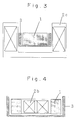
  • Fig. 3 is a diagram showing one practical embodiment of the present invention and a sectional view showing the constitution of composite magnet of Example 3.
  • Fig. 4 is a diagram showing one practical embodiment of the present invention and a sectional view showing the constitution of composite magnet of Example 4.
  • said superconductive bulk form and normal conductive or superconductive coil are arranged in the shape of holding the central axes thereof in common.
  • the embodiment of claim 2 of the present invention is one wherein the superconductive bulk form is arranged around the normal conductive or superconductive coil.
  • the superconductive bulk form is arranged around the normal conductive or superconductive coil.
  • Y 2 O 3 , BaCO 3 and CuO were mixed so as the ratio of Y:Ba:Cu to become 1.8:2.4:3.4 and calcined for 24 hours at 900 °C.
  • the mixture was quenched by using copper hammers and then pulverized finely using a mortar and pestle.
  • the pulverized powder was press-molded in a size of diameter of about 5 cm and height of 2 cm. After heating for 20 minutes at 1100 °C, this was cooled to 1000 °C over 1 hour and, after cooling to 900 °C at a rate of 1 °C per hour, it was cooled to room temperature in furnace. Thereafter, it was heated for 100 hours at 500 °C in oxygen of 1 atm.
  • the Bi type superconductor has a significant anisotropy.
  • the direction becomes advantageous for critical current, but the magnetic field exiting coil bends immediately, thus generating a magnetic field with parallel component to the face of the tape at the outer edge. For this reason, the generated magnetic field becomes small.
  • the bend of this magnetic field is suppressed and, in consequence, the critical current improves and the generating magnetic field also increases.

Landscapes

  • Engineering & Computer Science (AREA)
  • Power Engineering (AREA)
  • Superconductors And Manufacturing Methods Therefor (AREA)

Description

BACKGROUND OF THE INVENTION
The present invention relates to a bulk high-temperature superconductive magnet with freely variable strength of magnetic field obtainable by combining a high-temperature superconductive bulk form with high critical current with a superconductive coil, which allows the stabilization of conventional superconductive coil and the more extended application of superconductive magnet. The magnet with this structure is utilizable for, for example, the stabilization of superconductive coil for magnetic levitated train, etc.
With the discovery of oxide superconductor represented by R-Ba-Cu-O type (R denotes rare-earth elements, hereinafter it means the same) with critical temperature (Tc) exceeding 90 K, it has become possible to use liquid nitrogen as a coolant for superconductor. For putting the superconductor into practice, it is required to process this into a wire, tape or the like. It is the status quo however that, in this form, the critical current being most important in the practice of superconductor is low and has not reached the practical level at 77 K.
For example, Bi-Sr-Ca-Cu-O type superconductor is relatively easy to process into a tape. Thus, a tape with a length exceeding 100 m has already been made and a pancake coil that generates a magnetic field exceeding 1 T at 20 K is manufactured, but it exhibits only around 0.1 T at a temperature of liquid nitrogen at most.
In the case of Bi-Sr-Ca-Cu-O type material, the anisotropy is significant in the crystal structure and, while the critical current is relatively high when applying the magnetic field perpendicularly to the c-axis of crystal, it becomes very low when applying parallel, which is considered to be a problematic point at the time of using liquid nitrogen.
On the other hand, with R-Ba-Cu-O type superconductor made by melt process, the optimization of flux pinning effect has been achieved though in the state of bulk, and very high critical current at practical level is achieved even at a temperature of liquid nitrogen. Such bulk form exhibits a high repulsive force and attractive force through the interaction with magnetic field, hence application to bearing etc. is investigated. Moreover, trapping of magnetic field is also possible, leading to a magnetic field exceeding 1 T at a temperature of liquid nitrogen.
With the conventional superconductor, if attempting to use it in bulk form, the so-called quenching phenomenon, in which the superconductivity is broken abruptly by a small external disturbance, occurred because of low specific heat, making it impossible to utilize it in the stable state. In the case of a linear motor car, the practicality being investigated currently, this quenching is posing a problem. Whereas, the high-temperature superconductor has an advantage of being usable stably even in bulk.
As described above, there is a problem that, with bulk superconductor alone, high magnetic field can be generated, but the control of that generated magnetic field is difficult. Moreover, there is a problem that, with superconductive coil alone using a tape of high-temperature superconductor, the generating magnetic field can be controlled by the level of current, but the generating magnetic field is too weak at a temperature as high as that of liquid nitrogen.
In addition, while the superconductive coil capable of generating a large magnetic field is manufactured using low-temperature superconductive material and the application to linear motor car is investigated utilizing the mutual repulsion between magnets, it cannot necessarily be said that the practicality is high.
IEEE Translation Journal on Magnetics in Japan, vol. 6, July 1991, No. 7, pages 604-613 describes high-temperature oxide superconducting (YBa2Cu3O7-x) bulk cores and their application to quick response magnetic sensors. The superconducting cores were fabricated by compressing pre-sintered powders and sintering the resulted pellets at 910 to 1,000°C. The sintered pellets were tightly wound with polyester-covered copper wire and used as magnetic cores.
As a result of extensive investigations for overcoming the respective drawbacks of high-temperature superconductive bulk magnet, high-temperature superconductive coil and low-temperature superconductive coil, the inventors have known that a composite constituted by appropriately combining high-temperature superconductive bulk form with normal conductive or superconductive coil is possible to be utilized in the stable state, leading to the completion of the invention.
SUMMARY OF THE INVENTION
In one aspect the present invention relates to a composite magnet with a structure comprising a core of R-Ba-Cu-O type bulk superconductor made by melt process, enclosed around it with superconductive coil.
In another aspect, the present invention relates to a composite magnet consisting of a center of a normal conductive or superconductive coil, enclosed around it with ring-shaped R-Ba-Cu-O type bulk superconductor made by a melt process.
In a further aspect, the present invention relates to a composite magnet comprising a core of R-Ba-Cu-O type bulk superconductor made by a melt process, enclosed around it with a normal conductive or super conductive coil, further comprising a ring-shaped R-Ba-Cu-O type bulk superconductor made by a melt process which is disposed outside thereof.
BRIEF DESCRIPTION OF THE DRAWING
Fig. 1 is a diagram showing one practical embodiment of the present invention and a sectional view showing the constitution of composite magnet of Example 1.
Fig. 2 is a diagram showing one practical embodiment of the present invention and a sectional view showing the constitution of composite magnet of Example 2.
Fig. 3 is a diagram showing one practical embodiment of the present invention and a sectional view showing the constitution of composite magnet of Example 3.
Fig. 4 is a diagram showing one practical embodiment of the present invention and a sectional view showing the constitution of composite magnet of Example 4.
Fig. 5 is a diagram showing one practical embodiment of the present invention and a sectional view showing the constitution of composite magnet of Example 5.
DETAILED DESCRIPTION OF THE INVENTION
In the following, the invention will be illustrated in more detail referring to the drawings. Figs. 1 through 3 are diagrams each showing one practical embodiment of the present invention, and Figs. 4 and 5 show other embodiments of the present invention. In the diagrams, numeral 1 indicates a superconductive bulk form, numeral 2a, 2b or 2c, a normal conductive or superconductive coil, and numeral 3, a container.
The superconductive bulk form (1 in the diagrams) constituting the invention is a R-Ba-Cu-O type superconductor. R denotes rare-earth elements and comprises one or more elements selected from a group consisting of Y, Sm, Eu, Gd, Dy, Ho and Er. The proportion of the constituting components of this superconductor is not particularly restricted and it is only necessary to be a constituting proportion exhibiting the superconductivity. Moreover, this superconductor is one made by melt process, which gives high critical current even in a high magnetic field.
The normal conductive or superconductive coil shown by numeral 2a, 2b or 2c in the diagrams comprises, for example, normal conductive substances such as copper, Bi type and Nb-Ti type superconductive substances.
In the invention, said superconductive bulk form and normal conductive or superconductive coil are arranged in the shape of holding the central axes thereof in common.
The embodiment of claim 2 of the present invention is one wherein the superconductive bulk form is arranged around the normal conductive or superconductive coil. For more improving the synergistic effect due to such a combination of coil with bulk form, it is preferable to make the superconductive bulk form thicker than said coil in the thicknesses thereof in the direction of central axis.
These constitutional matters of the invention are accommodated in a container (3 in the diagrams) and the container is usually made of stainless steel.
When making the composite with the structure wherein the high-temperature superconductive bulk form is enclosed with superconductive coil, it becomes possible to actively control the magnetic field generated by the bulk magnet through the adjustment of the coil current. Also, when enclosing the coil made of high-temperature superconductor (e.g. Bi-Sr-Ca-Cu-O) with high-temperature superconductive (e.g. Y-Ba-Cu-O) bulk form, the bend at the outer edge portion of magnetic field is suppressed.
As described above, with Bi type material, the anisotropy of critical current is significant depending on the direction of magnetic field. Hence, with the pancake type coil manufactured with a tape using this material, the preferential direction may be available, but the influence in the direction of low critical current appears eventually because of the bend of magnetic field.
However, if covering the surroundings of said coil with bulk form as above, then the bend of magnetic field is suppressed and the critical current only in the preferential direction becomes available resulting in the improvement in generated magnetic field.
In addition, when arranging the high-temperature superconductive bulk at the center of low-temperature superconductive coil, even if the low-temperature superconductor may be quenched, for example, in the case of utilizing this for magnetic levitation etc., the bulk form keeps the state, thus allowing the alleviation of abrupt change.
In the following, the invention will be illustrated based on the examples.
Example 1
Y2O3, BaCO3 and CuO were mixed so as the ratio of Y:Ba:Cu to become 1.8:2.4:3.4 and calcined for 24 hours at 900 °C. After heating further for 20 minutes at 1400 °C, the mixture was quenched by using copper hammers and then pulverized finely using a mortar and pestle. The pulverized powder was press-molded in a size of diameter of about 5 cm and height of 2 cm. After heating for 20 minutes at 1100 °C, this was cooled to 1000 °C over 1 hour and, after cooling to 900 °C at a rate of 1 °C per hour, it was cooled to room temperature in furnace. Thereafter, it was heated for 100 hours at 500 °C in oxygen of 1 atm.
Next, around this Y-Ba-Cu-O superconductive material, a copper wire capable of passing a current of at highest 10 A was wound 1000 turns. The constitution is shown in Fig. 1. In the diagram, numeral (1) indicates the Y-Ba-Cu-O superconductor, numeral (2a), the copper coil and numeral (3), a container. With this coil, a magnetic field of about 0.1 T (1 KG) generates at the central portion in the state of passing a current of 5 A.
The superconductor was cooled in the state of passing the current of 5 A through the coil using liquid nitrogen and the current of coil was turned off. As a result of measuring the magnetic field at the central portion of the superconductor using a Hall sensor, it had 0.1T (1 KG). Following this, when passing a current of opposite direction through the coil, the magnetic field of the superconductor became smaller gradually, resulting in approximately zero at the outer circumference at 5 A.
As described, when using superconductor and copper coil, it becomes possible to control the magnetic field of the bulk superconductive magnet.
Example 2
Y-Ba-Cu-O superconductor was manufactured by the same method as manufactured in Example 1 and, around it, a Pb-Bi-Sr-Ca-Cu-O silver tape (critical temperature 105 K) made by powder-in-tube process was wound 100 turns in the shape of a pancake type coil. This tape has a critical current of about 12 A at a temperature of liquid nitrogen and a magnetic field of 0.05 T (500 G) generates only with coil.
A composite of this Y-Ba-Cu-O bulk superconductor with the Pb-Bi-Sr-Ca-Cu-O superconductive tape was dipped into liquid nitrogen and current was passed through the tape, but the inner magnetic field had approximately zero. This is because of that the magnetic field is shielded by the Y-Ba-Cu-O superconductor.
Here, next, as shown in Fig. 2, the Y-Ba-Cu-O superconductor (1) was placed in a stainless steel container (3) and separated from the Pb-Bi-Sr-Ca-Cu-O superconductive tape coil (2b). In this state, a current of 10 A was passed through the tape and then the Y-Ba-Cu-O superconductor was cooled with liquid nitrogen. Thereafter, the current of the tape was turned off. As a result of measuring the magnetic field at the central portion of superconductor with a Hall sensor, it had 0.05 T (500 G). Following this, when passing a current of opposite direction through the tape, the magnetic field in the superconductor decreased gradually resulting in the magnetic field at outer circumference being approximately zero at 10 A. In this way, by covering the surroundings of the bulk superconductor with normal conductive or superconductive coil, it becomes possible to make the magnetic field of the superconductor variable.
Example 3
A commercial NbTi superconductive coil (bore diameter 6 cm, maximum magnetic field at center 5 T) was prepared. Bore forms a space at room temperature. A stainless steel container was inserted into this bore. Next, a bulk Y-Ba-Cu-O superconductor (1) made by the method in Example 1 was placed in a stainless steel container (3). The constitution is shown in Fig. 3. In the state of being 2 T excited by the NbTi superconductive coil (2c), the superconductor was cooled with liquid nitrogen. Following this, even if demagnetizing the outer superconductive coil, the bulk superconductor remained to trap the magnetic field of 2 T.
In this state, an overcurrent was passed through the coil to quench. Thereafter, as a result of measuring the magnetic field of the bulk superconductor, it remained to be 2 T. In this way, with the superconductive coil with a core of bulk superconductor, even if the low-temperature superconductive coil may be quenched, the high-temperature superconductor can maintain the magnetic field to some extent, making it possible to hinder an abrupt change in magnetic field.
Example 4
By the same method as in Example 1, two 10 cm diameter and 4 cm high Y-Ba-Cu-O superconductors were manufactured. At the central portion thereof, a 8 cm diameter bore was provided. Next, a Pb-Bi-Sr-Ca-Cu-O superconductive tape wound in the shape of about 7.5 cm diameter pancake type coil was prepared. The generated magnetic field of this coil at a temperature of liquid nitrogen was 0.1 T (1 KG).
As shown in Fig. 4, this pancake coil (2b) was placed in a ring of Y-Ba-Cu-O superconductor (1) and current was supplied. When measuring the generated magnetic field, the magnetic field increased to 0.2 T (2 KG). This is because of that the bend of magnetic field at the outer edge of coil was suppressed by the Y-Ba-Cu-O superconductive ring. Besides, the thickness of coil (2b) in the axial direction was made thinner than that of superconductor (1) as shown in Fig. 4.
Namely, the Bi type superconductor has a significant anisotropy. Hence, when applying the magnetic field perpendicularly to the face of the tape, the direction becomes advantageous for critical current, but the magnetic field exiting coil bends immediately, thus generating a magnetic field with parallel component to the face of the tape at the outer edge. For this reason, the generated magnetic field becomes small. However, when enclosing around the coil with the Y-Ba-Cu-O superconductor ring, the bend of this magnetic field is suppressed and, in consequence, the critical current improves and the generating magnetic field also increases.
Example 5
By the same method as in Example 1, two 4 cm diameter and 2 cm high and 10 cm diameter and 3 cm high Y-Ba-Cu-O superconductors were manufactured. Next, a 8 cm diameter bore was provided through the 10 cm diameter Y-Ba-Cu-O superconductor to process to ring shape. And, as shown in Fig. 5, the 4 cm diameter Y-Ba-Cu-O superconductor (1) was placed in a stainless steel container (3), Pb-Bi-Sr-Ca-Cu-O superconductive tape coil (2b) with same quality as used in Example 2 was wound therearound, and further the surroundings thereof was enclosed with the 10 cm outer diameter Y-Ba-Cu-O superconductor ring (1).
Cooling was made with liquid nitrogen except the innermost portion and, when passing a current through the tape in this state, a magnetic field of about 0.2 T (2 KG) generated at the central portion. Next, the innermost Y-Ba-Cu-O superconductor was cooled with liquid nitrogen and the power source of the tape was turned off. In this state, a magnetic field of 0.2 T (2 KG) generated in the innermost superconductor. In such a structure, the magnetic field of Pb-Bi-Sr-Ca-Cu-O superconductive tape coil generates effectively by the outermost Y-Ba-Cu-O superconductor and the innermost Y-Ba-Cu-O superconductor acts as a magnet.
Example 6
By the same method as in Example 1, R-Ba-Cu-O (R:Sm, Eu, Gd, Dy, Ho or Er) superconductors (diameter 4 cm, height 2 cm) were manufactured. However, in the last heat treatment, the starting temperatures for gradual cooling were made as follows: Sm:1060 °C, Eu:1050 °C, Gd:1030 °C, Dy:1010 °C, Ho:990 °C and Er:980 °C. Using these as the cores, copper coil was wound around each of them. When examining the characteristic thereof, it was confirmed that all recorded a central magnetic field of about 0.1 T (1 KG) and, when inverted the current, the magnetic fields at the outer circumference became zero.
As described above, in accordance with the invention, the control of generating magnetic field is easy and relatively strong magnetic field can be obtained even at a temperature as high as that of liquid nitrogen.

Claims (5)

  1. A composite magnet comprising a core (1) of a R-Ba-Cu-O type bulk superconductor, R denoting rare-earth elements, made by melt process, enclosed around it with a superconductive coil (2a, 2b, 2c).
  2. A composite magnet consisting of a center of a normal conductive or superconductive coil (2b), enclosed around it with a ring-shaped R-Ba-Cu-O type bulk superconductor (1), R denoting rare-earth elements, made by melt process.
  3. The composite magnet of claim 2, wherein the ring-shaped bulk superconductor (1) has a thickness in axial direction larger than that of the normal conductive or superconductive coil (2b).
  4. A composite magnet comprising a core (1) of a R-Ba-Cu-O type bulk superconductor, R denoting rare-earth elements, made by melt process, enclosed around it with a normal conductive or superconductive coil (2a, 2b, 2c), further comprising a ring-shaped R-Ba-Cu-O type bulk superconductor (1), R: same as above, made by melt process, which is disposed outside thereof.
  5. The composite magnet of any ofclaims 1 through 4, wherein the rare-earth elements are one or more elements selected from the group consisting of Y, Sm, Eu, Gd, Dy, Ho and Er.
EP94116095A 1993-10-13 1994-10-12 Composite of high-temperature superconductive bulk form with coil magnet Expired - Lifetime EP0649151B1 (en)

Applications Claiming Priority (3)

Application Number Priority Date Filing Date Title
JP5280126A JP2974108B2 (en) 1993-10-13 1993-10-13 Composite of high temperature superconducting bulk and coil magnet
JP28012693 1993-10-13
JP280126/93 1993-10-13

Publications (2)

Publication Number Publication Date
EP0649151A1 EP0649151A1 (en) 1995-04-19
EP0649151B1 true EP0649151B1 (en) 1999-12-29

Family

ID=17620702

Family Applications (1)

Application Number Title Priority Date Filing Date
EP94116095A Expired - Lifetime EP0649151B1 (en) 1993-10-13 1994-10-12 Composite of high-temperature superconductive bulk form with coil magnet

Country Status (4)

Country Link
US (1) US5543768A (en)
EP (1) EP0649151B1 (en)
JP (1) JP2974108B2 (en)
DE (1) DE69422368T2 (en)

Families Citing this family (15)

* Cited by examiner, † Cited by third party
Publication number Priority date Publication date Assignee Title
US6111490A (en) * 1996-06-19 2000-08-29 Aisin Seiki Kabushiki Kaisha Superconducting magnet apparatus and method for magnetizing superconductor
DE19717283C1 (en) * 1997-04-24 1998-04-23 Karlsruhe Forschzent Method of contact free longitudinal and transversal homogeneity examination of critical current density in strip supraconductors
JPH11248810A (en) * 1998-02-27 1999-09-17 Rikagaku Kenkyusho Nuclear magnetic resonance equipment
WO2001004646A1 (en) * 1999-07-13 2001-01-18 Los Alamos National Laboratory Apparatus for measurement of critical current in superconductive tapes
JP3094104B1 (en) * 1999-08-31 2000-10-03 工業技術院長 Superconducting magnetic levitation transport system
JP4194061B2 (en) 1999-09-24 2008-12-10 財団法人鉄道総合技術研究所 Method of magnetizing a plurality of bulk superconducting magnet assemblies with different magnetic poles
JP4283406B2 (en) * 2000-01-27 2009-06-24 新日本製鐵株式会社 Method and apparatus for magnetizing oxide superconducting material
JP4317646B2 (en) * 2000-06-26 2009-08-19 独立行政法人理化学研究所 Nuclear magnetic resonance apparatus
DE10033869C2 (en) 2000-07-12 2003-07-31 Karlsruhe Forschzent HTS cryomagnet and magnetization process
JP5247957B2 (en) * 2001-05-31 2013-07-24 公益財団法人国際超電導産業技術研究センター Permanent current switch and its usage
DE102004043989B3 (en) * 2004-09-11 2006-05-11 Bruker Biospin Gmbh Superconductive Magnetspulenanrodnung
JP4807120B2 (en) * 2006-03-23 2011-11-02 アイシン精機株式会社 Superconducting magnetic field generator and sputtering film forming apparatus
CN101192463B (en) * 2006-11-29 2011-06-22 上海磁浮交通工程技术研究中心 High-temperature superconducting magnets applied to electromagnetic levitation high-speed maglev trains
JP4743150B2 (en) * 2007-04-17 2011-08-10 住友電気工業株式会社 Superconducting coil and superconducting conductor used therefor
US20160351310A1 (en) * 2013-05-29 2016-12-01 Christopher Mark Rey Low Temperature Superconductive and High Temperature Superconductive Amalgam Magnet

Family Cites Families (8)

* Cited by examiner, † Cited by third party
Publication number Priority date Publication date Assignee Title
DE3829207A1 (en) * 1988-08-29 1990-03-08 Licentia Gmbh Current-limiting induction coil
DE69003022T2 (en) * 1989-06-23 1994-04-14 Ibm Controllable levitation / suspension in a magnetic superconductor system.
JPH0416510A (en) * 1990-05-07 1992-01-21 Nippon Steel Corp Production of oxide superconducting bulk material
EP0486698B1 (en) * 1990-06-07 1995-11-08 Nippon Steel Corporation Oxide superconductor and production thereof
JPH0533827A (en) * 1991-07-26 1993-02-09 Showa Electric Wire & Cable Co Ltd Vibration isolation device
US5289150A (en) * 1991-08-30 1994-02-22 Electric Power Research Institute Method and apparatus for superconducting trapped-field energy storage and power stabilization
FR2688356A1 (en) * 1992-03-06 1993-09-10 Alsthom Cge Alcatel Current limiter using series inductance with a magnetic circuit equipped with a superconducting sheath
DE4226942C1 (en) * 1992-08-14 1994-05-26 Daimler Benz Ag Nonlinear inductive component, e.g. B. Choke and method of manufacturing the choke core

Also Published As

Publication number Publication date
JP2974108B2 (en) 1999-11-08
DE69422368D1 (en) 2000-02-03
DE69422368T2 (en) 2000-08-24
JPH07111213A (en) 1995-04-25
US5543768A (en) 1996-08-06
EP0649151A1 (en) 1995-04-19

Similar Documents

Publication Publication Date Title
US5543768A (en) Composite of high-temperature superconductive bulk form with coil magnet
US5426408A (en) Ceramic superconducting magnet using stacked modules
EP0772208A2 (en) Oxide-superconducting coil and a method for manufacturing the same
AU604827B2 (en) New superconductive compounds of the k2nif4 structural type having a high transition temperature, and method for fabricating same
JPH0643268B2 (en) Oxide high temperature superconductor
Haldar et al. Transport critical current densities of silver clad Bi‐Pb‐Sr‐Ca‐Cu‐O tapes at liquid helium and hydrogen temperatures
EP0292436B1 (en) High current conductors and high field magnets using anisotropic superconductors
US6584333B1 (en) Protected superconducting component and method for producing the same
US5659278A (en) Superconducting magnet device, magnetizing device and method for superconductor
Motowidlo et al. Influence of filament size and atmosphere on the microstructure and Jc of round multifilament Bi2Sr2Ca1Cu2Ox wires
Kitaguchi et al. Advances in Bi-Based High-Tc superconducting tapes and wires
JP4011131B2 (en) Tape-shaped oxide superconducting wire, superconducting magnet and current lead using the same
US8060169B1 (en) Superconductive compounds having high transition temperature, and methods for their use and preparation
JP3090709B2 (en) Oxide superconducting wire and method of manufacturing the same
JP2651018B2 (en) High magnetic field magnet
Jian-xun High T c superconducting materials for strong current applications: Approach at the first stage
JP2509642B2 (en) Superconducting power lead manufacturing method
Ohmatsu et al. Recent progress of HTS magnet using Bi-2223 Ag-sheathed wire
Tenbrink et al. Manufacture and properties of Bi-2212-based Ag-sheathed wires
JP2563391B2 (en) Superconducting power lead
JPH06243737A (en) Oxide superconducting coil
JPH06231950A (en) Superconducting magnet
JPH07130533A (en) Superconducting current lead and superconducting device using the same
Flükiger et al. Next generation superconductors for high field applications
Wires Manufacture and Properties of Bi-2212-Based

Legal Events

Date Code Title Description
PUAI Public reference made under article 153(3) epc to a published international application that has entered the european phase

Free format text: ORIGINAL CODE: 0009012

AK Designated contracting states

Kind code of ref document: A1

Designated state(s): DE FR GB

17P Request for examination filed

Effective date: 19950814

17Q First examination report despatched

Effective date: 19950914

GRAG Despatch of communication of intention to grant

Free format text: ORIGINAL CODE: EPIDOS AGRA

GRAG Despatch of communication of intention to grant

Free format text: ORIGINAL CODE: EPIDOS AGRA

GRAH Despatch of communication of intention to grant a patent

Free format text: ORIGINAL CODE: EPIDOS IGRA

GRAH Despatch of communication of intention to grant a patent

Free format text: ORIGINAL CODE: EPIDOS IGRA

GRAA (expected) grant

Free format text: ORIGINAL CODE: 0009210

AK Designated contracting states

Kind code of ref document: B1

Designated state(s): DE FR GB

REF Corresponds to:

Ref document number: 69422368

Country of ref document: DE

Date of ref document: 20000203

ET Fr: translation filed
PLBE No opposition filed within time limit

Free format text: ORIGINAL CODE: 0009261

STAA Information on the status of an ep patent application or granted ep patent

Free format text: STATUS: NO OPPOSITION FILED WITHIN TIME LIMIT

26N No opposition filed
REG Reference to a national code

Ref country code: GB

Ref legal event code: IF02

PGFP Annual fee paid to national office [announced via postgrant information from national office to epo]

Ref country code: DE

Payment date: 20071004

Year of fee payment: 14

PGFP Annual fee paid to national office [announced via postgrant information from national office to epo]

Ref country code: GB

Payment date: 20071010

Year of fee payment: 14

Ref country code: FR

Payment date: 20071009

Year of fee payment: 14

GBPC Gb: european patent ceased through non-payment of renewal fee

Effective date: 20081012

REG Reference to a national code

Ref country code: FR

Ref legal event code: ST

Effective date: 20090630

PG25 Lapsed in a contracting state [announced via postgrant information from national office to epo]

Ref country code: DE

Free format text: LAPSE BECAUSE OF NON-PAYMENT OF DUE FEES

Effective date: 20090501

PG25 Lapsed in a contracting state [announced via postgrant information from national office to epo]

Ref country code: FR

Free format text: LAPSE BECAUSE OF NON-PAYMENT OF DUE FEES

Effective date: 20081031

PG25 Lapsed in a contracting state [announced via postgrant information from national office to epo]

Ref country code: GB

Free format text: LAPSE BECAUSE OF NON-PAYMENT OF DUE FEES

Effective date: 20081012