EP0649130A1 - Objective lens posture adjusting mechanism for optical pickup - Google Patents
Objective lens posture adjusting mechanism for optical pickup Download PDFInfo
- Publication number
- EP0649130A1 EP0649130A1 EP94116272A EP94116272A EP0649130A1 EP 0649130 A1 EP0649130 A1 EP 0649130A1 EP 94116272 A EP94116272 A EP 94116272A EP 94116272 A EP94116272 A EP 94116272A EP 0649130 A1 EP0649130 A1 EP 0649130A1
- Authority
- EP
- European Patent Office
- Prior art keywords
- objective lens
- support base
- optical system
- cylindrical surfaces
- adjusting mechanism
- Prior art date
- Legal status (The legal status is an assumption and is not a legal conclusion. Google has not performed a legal analysis and makes no representation as to the accuracy of the status listed.)
- Granted
Links
- 230000003287 optical effect Effects 0.000 title claims abstract description 62
- 230000007246 mechanism Effects 0.000 title claims abstract description 23
- 239000000853 adhesive Substances 0.000 description 5
- 230000004048 modification Effects 0.000 description 4
- 238000012986 modification Methods 0.000 description 4
- 230000008859 change Effects 0.000 description 3
- 239000000463 material Substances 0.000 description 2
- 238000005452 bending Methods 0.000 description 1
- 238000010586 diagram Methods 0.000 description 1
- 239000002184 metal Substances 0.000 description 1
- 229920003051 synthetic elastomer Polymers 0.000 description 1
- 229920003002 synthetic resin Polymers 0.000 description 1
- 239000000057 synthetic resin Substances 0.000 description 1
- 239000005061 synthetic rubber Substances 0.000 description 1
- 230000008719 thickening Effects 0.000 description 1
Images


Classifications
-
- G—PHYSICS
- G11—INFORMATION STORAGE
- G11B—INFORMATION STORAGE BASED ON RELATIVE MOVEMENT BETWEEN RECORD CARRIER AND TRANSDUCER
- G11B7/00—Recording or reproducing by optical means, e.g. recording using a thermal beam of optical radiation by modifying optical properties or the physical structure, reproducing using an optical beam at lower power by sensing optical properties; Record carriers therefor
- G11B7/12—Heads, e.g. forming of the optical beam spot or modulation of the optical beam
- G11B7/22—Apparatus or processes for the manufacture of optical heads, e.g. assembly
-
- G—PHYSICS
- G11—INFORMATION STORAGE
- G11B—INFORMATION STORAGE BASED ON RELATIVE MOVEMENT BETWEEN RECORD CARRIER AND TRANSDUCER
- G11B7/00—Recording or reproducing by optical means, e.g. recording using a thermal beam of optical radiation by modifying optical properties or the physical structure, reproducing using an optical beam at lower power by sensing optical properties; Record carriers therefor
- G11B7/08—Disposition or mounting of heads or light sources relatively to record carriers
- G11B7/082—Aligning the head or the light source relative to the record carrier otherwise than during transducing, e.g. adjusting tilt set screw during assembly of head
Definitions
- the present invention generally relates to an optical pickup of an optical disk drive, and more particularly to an optical lens posture adjusting mechanism for an optical pickup.
- Reference numeral 1 represents a laser diode which emits a laser beam.
- the laser beam emitted from the laser diode 1 passes through a diffraction grating 2, is reflected by a beam splitter 3, and is incident upon a collimator lens 4.
- the laser beam is converted into a parallel beam by the collimator lens 4, reflected by a mirror 5, and is incident upon an objective lens 6.
- the laser beam incident upon the objective lens is converged on a signal recording surface of an optical disk 9.
- the laser beam applied to the optical disk 9 is reflected by the signal recording surface, and becomes incident upon the beam splitter 3 via the objective lens 6, mirror 5, and collimator lens 4 along the pass opposite to the incident laser beam.
- Most of the laser rays incident upon the beam splitter 3 transmit the beam splitter 3 and are incident upon a convex lens 7.
- the laser beam is converged by the convex leans 7 onto a light receiving surface of a photodiode 8 and the information recorded on the optical disk 9 is read.
- FIG. 10 represents an optical system support base which supports an optical system excepting an objective lens.
- An objective lens support base 11 is mounted with a printed circuit board 13 by screws.
- the printed circuit board 13 resiliently supports a lens holder 6a by means of four resilient members 14.
- Two pairs of confronting yokes 11b and 11c are mounted on the objective lens support base 11. Magnets 12 are mounted on the yokes 11c.
- the objective lens 6 is secured to the lens holder 6a, and the yokes 11b are inserted into holes formed in the lens holder 6a.
- a tracking coil and a focussing coil for interacting with a magnetic field generated by the yokes and magnets are secured to the lens holder 6a.
- a spherical convex 11a is formed at the objective lens support base 11, and a spherical concave 10a in surface contact with the spherical convex 11a is formed at the optical system support base 10.
- the objective lens support base 11 is aligned with the optical system support base 10 by making the spherical convex 11a in surface contact with the spherical concave 10a, and held in position by screws 17 and 15.
- the screws 17 are inserted into washers and holes formed in the optical system support base 10, and threaded into tapped holes formed in the objective lens support base 11.
- the objective lens support base 11 is attracted toward the optical system support base 10 by the force of the coil spring 15, and the spherical convex 11a is maintained in tight contact with the spherical concave 10a.
- the above-described object lens posture adjusting mechanism of an optical pickup adjusts the rotary angle of the objective lens about the X- and Y-axes by using two screws.
- adjustment is not easy because the objective lens rotates about both the X- and Y- axes even if one of the screws is rotated.
- the spherical convex 11a is formed on the central bottom surface of the objective lens support base 11, so that it is difficult to observe the contact conditions of the surfaces of the spherical convex 11a and concave 10a. If a surface contact is not perfect, a sufficient contact force at the bonded surfaces after the adjustment cannot be ensured. Also, there is a problem that adhesive agent is difficult to be applied to the whole contact surfaces.
- the mirror is required to mount under the spherical convex, thickening the optical pickup.
- the invention has been made under such circumstances, and it is an object of the present invention to provide an objective lens posture adjusting mechanism of an optical pickup capable of eliminating the influence of adjustment at least about one axis upon the rotary angle about the other axis.
- an objective lens posture adjusting mechanism of an optical pickup for adjusting an inclination angle of an objective lens about two axes relative to an optical system support base, wherein an intermediate base is superposed upon the optical system support base via first cylindrical surfaces, an object lens support base is superposed upon the intermediate base via second cylindrical surfaces having a center axis not parallel to a center axis of the first cylindrical surfaces, and the inclination angle of the objective lens about the two axes is adjusted by relative rotations of the first and second cylindrical surfaces.
- the center of the objective lens is made flush with the center axes of the first and second cylindrical surfaces.
- two tapped holes and one loose hole are formed in the intermediate base at positions not extending on one straight line
- a tapped hole is formed in the objective lens support base at the position corresponding to the loose hole
- two screws are threaded into the two tapped holes via two holes formed in the optical system support base at the positions corresponding to the two tapped holes
- one screw is threaded into the one tapped hole of the objective lens support base via a spring and a hole formed in the optical system support base at the position corresponding to the loose hole of the intermediate base
- the intermediate base and the objective lens support base superposed via the second cylindrical surfaces are biased by a spring at the position opposite to the tapped hole of the objective lens support base so as to make the intermediate base and the objective lens support base come near each other
- the inclination angle of the object lens about the two axis is adjusted by rotating each of the three screws.
- the intermediate base is fixed to the optical system support base, and without moving the intermediate base, the inclination angle about only one axis can be adjusted by relative rotations of the first cylindrical contact surfaces between the intermediate base and the objective lens support base.
- the center of the objective lens is made flush with the center axes of the first and second cylindrical contact surfaces, the height of the objective lens will not change during adjustment, and the posture adjustment will not result in an off-focus state.
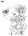
- Fig.1 is a broken perspective view showing the main part of an objective lens posture adjusting mechanism of an optical pickup according to an embodiment of the present invention.
- Fig.2A is an elevational cross sectional view of the objective lens posture adjusting mechanism taken along a bent line
- Fig.2B is a traverse cross sectional view of the objective lens posture adjusting mechanism
- Fig.2C is a partial cross sectional view showing a modification of the objective lens posture adjusting mechanism.
- Fig.3 is a perspective view showing modifications of a C-shaped spring used by the objective lens posture adjusting mechanism.
- Fig.4 is a broken perspective view showing an example of a conventional objective lens posture adjusting mechanism of an optical pickup.
- Fig.5 is a diagram illustrating an optical path of an optical pickup.
- FIG.1 to 3 An objective lens posture adjustment mechanism of an optical pickup according to an embodiment of the invention will be described with reference to Figs.1 to 3.
- elements having the same functions as a conventional mechanism are represented by using identical reference numerals, and the description thereof is omitted.
- reference numeral 18 represents an intermediate base having striped cylindrical convexes 18a and 18b between which a rectangular hole 18c is provided. Striped cylindrical concaves 10b and 10c in surface contact with the striped cylindrical convexes 18a and 18b are formed at an optical system support base 10. A mirror 5 is mounted on the optical system support base 10 between the striped cylindrical concaves 10a and 10b.
- striped cylindrical convexes 22a and 22b are formed at an objective lens support base 22.
- a rectangular hole 18d and a recess 18e are formed in the intermediate base 18 which are in line contact with the striped cylindrical convexes 22a and 22b.
- the objective lens support base 22 is formed with a bent piece 22c on which a printed circuit board 13 is mounted and yokes 22d and 22e formed by bending and cutting/folding.
- the printed circuit board 13 resiliently supports a lens holder 6a by four resilient members 14.
- a magnet 12 is mounted on the yoke 22e.
- An objective lens 6 is secured to the lens holder 6a, and the yokes 22d and 22e and magnet 12 are inserted into a hole formed in the lens holder 6a.
- a tracking coil and a focussing coil for interacting with a magnetic field generated by the yokes and magnet are secured to the lens holder 6a.
- the optical system support base 10 and intermediate base 18, and the intermediate base 18 and objective lens support base 22 are coupled by screws 19, 20, and 21.
- the screw 19 is threaded via a flanged hole 10d formed in the optical system support base 10 into a tapped hole 18f formed in the intermediate base 18.
- the screw 20 is threaded via a flanged hole 10e formed in the optical system support base 10 into a tapped hole 18g formed in the intermediate base 18.
- the screw 21 is inserted into a coil spring 16, a stepped hole 10f of the optical system support base 10, and a stepped hole 18h of the intermediate base 18, and threaded into a tapped hole 22f formed in the objective lens support base 22.
- the intermediate base 18 and objective lens support base 22 are coupled together by a C-shaped spring 23 at the right side thereof so as to make both the bases 18 and 22 come near each other.
- the intermediate base 18 and objective lens support base 22 are mounted on the optical system support base 10 by the screw in the manner described above, and a laser beam passing through the objective lens 6 is reflected by the mirror 5 and guided to the optical system such as shown in Fig.5.
- the posture of the objective lens 6 is adjusted by the screws 19, 20, and 21 by adjusting the rotary angle of cylindrical contact surfaces between the optical system support base 10 and intermediate base 18 and between the intermediate base 18 and the objective lens support base 22.
- the heights of the tapped hole of the intermediate base 18 into which the screws 19 and 20 are threaded change with the rotary angle of the intermediate base 10 about the cylindrical contact surfaces. Therefore, the rotary angle can be adjusted by adjusting the threading amount of the screws 19 and 20.
- the cylindrical contact surfaces can be maintained wholly in an contact state by setting the rotation angle ratio of the screws 19 and 20 to a proper value.
- the objective lens support base 22 is applied with resilient forces of the C-shaped spring 23 and the coil spring 16 at the right and left sides of the base 22.
- the C-shaped spring 23 biases the objective lens support base 22 in the counter clockwise direction about the line contact area of the striped convexes 22a and 22b
- the coil spring 16 fitted around the screw 21 biases the objective lens support base 22 in the clockwise direction about the line contact area of the striped convexes 22a and 22b.
- the rotary angle of the objective lens support base 22 about the line contact area can be therefore adjusted by changing the resilient force of the coil spring 16 by adjusting the rotation amount of the screw 21.
- the height of the objective lens 6 will not change and its focal point will not be shifted even if the posture of the objective lens 6 is adjusted by adjusting the rotary angles about the cylindrical contact areas and lines.
- the resilient force of the coil spring 16 attracts the objective lens support base 22 and intermediate base 18 toward the optical system support base 10 to tightly contact the cylindrical convexes with the cylindrical concaves and the end lines of the rectangular hole.
- the whole of the tight contact areas or lines can be observed from both the sides of areas or lines. It is therefore easy to maintain the cylindrical contact areas or lines in a perfect contact state. With a good contact state, the bonding force of adhesive agent applied after the adjustment can be increased.
- FIG.2C A modification of the optical system support base 10 is shown in Fig.2C.
- the cylindrical convex of the intermediate base 18 is supported by a wedge-like hollow formed in the optical system support base 10.
- a rectangular groove may be formed to support the cylindrical convex of the intermediate base 18.
- a spring indicated at (a) in Fig.3 is formed by a plate spring like the embodiment. However, the opposite ends are bent.
- a spring indicated at (b) in Fig.3 is formed by a wire spring bent in generally a channel shape.
- a spring indicated at (c) is formed by a wire spring bend circularly.
- a material having an elasticity may be used, such as metal, synthetic resin, and rubber.
- the whole of the tight contact areas or lines can be observed from both the sides of areas or lines. It is therefore easy to maintain the cylindrical contact areas or lines in a perfect contact state. With a good contact state, the bonding force of adhesive agent applied after the adjustment can be increased. Adhesive agent is easy to be coated from both the sides of areas or lines.
- the rotary angle at least about one cylindrical contact areas or lines can be adjusted independently so that the posture of an objective lens can be easily adjusted.
- a mirror can be mounted in the rectangular hole formed between the cylindrical convexes so that the optical pickup can be thinned.
- a cylindrical plane can be worked easier than a spherical plane, providing a high precision component.
Landscapes
- Physics & Mathematics (AREA)
- Optics & Photonics (AREA)
- Moving Of The Head For Recording And Reproducing By Optical Means (AREA)
- Optical Head (AREA)
- Optical Recording Or Reproduction (AREA)
- Mounting And Adjusting Of Optical Elements (AREA)
- Lens Barrels (AREA)
Abstract
Description
- The present invention generally relates to an optical pickup of an optical disk drive, and more particularly to an optical lens posture adjusting mechanism for an optical pickup.
- An example of the structure of an optical pickup of an optical disk drive is shown in Fig.5. Reference numeral 1 represents a laser diode which emits a laser beam. The laser beam emitted from the laser diode 1 passes through a diffraction grating 2, is reflected by a beam splitter 3, and is incident upon a collimator lens 4. The laser beam is converted into a parallel beam by the collimator lens 4, reflected by a
mirror 5, and is incident upon anobjective lens 6. - The laser beam incident upon the objective lens is converged on a signal recording surface of an optical disk 9. The laser beam applied to the optical disk 9 is reflected by the signal recording surface, and becomes incident upon the beam splitter 3 via the
objective lens 6,mirror 5, and collimator lens 4 along the pass opposite to the incident laser beam. Most of the laser rays incident upon the beam splitter 3 transmit the beam splitter 3 and are incident upon a convex lens 7. The laser beam is converged by the convex leans 7 onto a light receiving surface of aphotodiode 8 and the information recorded on the optical disk 9 is read. - In order to correctly read information by such an optical pickup, it is necessary to make the objective lens apply a laser beam to an optical disk in the direction perpendicular to the recording surface thereof and be reflected by the recording surface in the perpendicular direction, and to make the reflected laser beam be converged to the
photodiode 8. To this end, the optical axis of a laser beam reflected by the objective lens is required to be coincident with the optical axis of a laser beam guiding optical system. An example of a conventional objective lens posture adjusting mechanism is shown in Fig.4.Reference numeral 10 represents an optical system support base which supports an optical system excepting an objective lens. An objectivelens support base 11 is mounted with a printedcircuit board 13 by screws. The printedcircuit board 13 resiliently supports alens holder 6a by means of fourresilient members 14. - Two pairs of confronting
yokes lens support base 11.Magnets 12 are mounted on theyokes 11c. Theobjective lens 6 is secured to thelens holder 6a, and theyokes 11b are inserted into holes formed in thelens holder 6a. A tracking coil and a focussing coil for interacting with a magnetic field generated by the yokes and magnets are secured to thelens holder 6a. - A
spherical convex 11a is formed at the objectivelens support base 11, and a spherical concave 10a in surface contact with thespherical convex 11a is formed at the opticalsystem support base 10. The objectivelens support base 11 is aligned with the opticalsystem support base 10 by making thespherical convex 11a in surface contact with the spherical concave 10a, and held in position byscrews - As specifically shown in Fig.5, the
screws 17 are inserted into washers and holes formed in the opticalsystem support base 10, and threaded into tapped holes formed in the objectivelens support base 11. In the above manner, the objectivelens support base 11 is attracted toward the opticalsystem support base 10 by the force of thecoil spring 15, and thespherical convex 11a is maintained in tight contact with the spherical concave 10a. - By adjusting the threading amount of two
screws 17, the rotary angle of theobjective lens 6 about the X- and Y-axes shown in Fig.4 is controlled. A laser beam entering theobjective lens 6 passes through holes formed in thespherical convex 11a and concave 10a at the centers thereof. - The above-described object lens posture adjusting mechanism of an optical pickup adjusts the rotary angle of the objective lens about the X- and Y-axes by using two screws. However, adjustment is not easy because the objective lens rotates about both the X- and Y- axes even if one of the screws is rotated.
- Furthermore, the
spherical convex 11a is formed on the central bottom surface of the objectivelens support base 11, so that it is difficult to observe the contact conditions of the surfaces of thespherical convex 11a and concave 10a. If a surface contact is not perfect, a sufficient contact force at the bonded surfaces after the adjustment cannot be ensured. Also, there is a problem that adhesive agent is difficult to be applied to the whole contact surfaces. - Still further, space for the mirror is not available because the hole formed in the
spherical convex 11a is circular. Therefore, the mirror is required to mount under the spherical convex, thickening the optical pickup. - The invention has been made under such circumstances, and it is an object of the present invention to provide an objective lens posture adjusting mechanism of an optical pickup capable of eliminating the influence of adjustment at least about one axis upon the rotary angle about the other axis.
- It is another object of the present invention to provide an objective lens posture adjusting mechanism of an optical pickup easy to observe a surface contact state and apply adhesive agent to the surface contact area after the adjustment.
- It is a further object of the present invention to provide an object lens posture adjusting mechanism capable of thinning an optical pickup by forming a rectangular hole at the surface contact area and disposing a mirror in the hole.
- According to one aspect of the present invention, there is provided an objective lens posture adjusting mechanism of an optical pickup for adjusting an inclination angle of an objective lens about two axes relative to an optical system support base, wherein an intermediate base is superposed upon the optical system support base via first cylindrical surfaces, an object lens support base is superposed upon the intermediate base via second cylindrical surfaces having a center axis not parallel to a center axis of the first cylindrical surfaces, and the inclination angle of the objective lens about the two axes is adjusted by relative rotations of the first and second cylindrical surfaces.
- According to another aspect of the present invention, the center of the objective lens is made flush with the center axes of the first and second cylindrical surfaces.
- According to a further aspect of the invention, two tapped holes and one loose hole are formed in the intermediate base at positions not extending on one straight line, a tapped hole is formed in the objective lens support base at the position corresponding to the loose hole, two screws are threaded into the two tapped holes via two holes formed in the optical system support base at the positions corresponding to the two tapped holes, one screw is threaded into the one tapped hole of the objective lens support base via a spring and a hole formed in the optical system support base at the position corresponding to the loose hole of the intermediate base, the intermediate base and the objective lens support base superposed via the second cylindrical surfaces are biased by a spring at the position opposite to the tapped hole of the objective lens support base so as to make the intermediate base and the objective lens support base come near each other, and the inclination angle of the object lens about the two axis is adjusted by rotating each of the three screws.
- According to the object lens posture adjusting mechanism of an optical pickup, the intermediate base is fixed to the optical system support base, and without moving the intermediate base, the inclination angle about only one axis can be adjusted by relative rotations of the first cylindrical contact surfaces between the intermediate base and the objective lens support base.
- Furthermore, since the center of the objective lens is made flush with the center axes of the first and second cylindrical contact surfaces, the height of the objective lens will not change during adjustment, and the posture adjustment will not result in an off-focus state.
- Fig.1 is a broken perspective view showing the main part of an objective lens posture adjusting mechanism of an optical pickup according to an embodiment of the present invention.
- Fig.2A is an elevational cross sectional view of the objective lens posture adjusting mechanism taken along a bent line, Fig.2B is a traverse cross sectional view of the objective lens posture adjusting mechanism, and Fig.2C is a partial cross sectional view showing a modification of the objective lens posture adjusting mechanism.
- Fig.3 is a perspective view showing modifications of a C-shaped spring used by the objective lens posture adjusting mechanism.
- Fig.4 is a broken perspective view showing an example of a conventional objective lens posture adjusting mechanism of an optical pickup.
- Fig.5 is a diagram illustrating an optical path of an optical pickup.
- An objective lens posture adjustment mechanism of an optical pickup according to an embodiment of the invention will be described with reference to Figs.1 to 3. In Figs.1 to 3, elements having the same functions as a conventional mechanism are represented by using identical reference numerals, and the description thereof is omitted.
- Referring to Fig.1,
reference numeral 18 represents an intermediate base having stripedcylindrical convexes rectangular hole 18c is provided. Stripedcylindrical concaves cylindrical convexes system support base 10. Amirror 5 is mounted on the opticalsystem support base 10 between the stripedcylindrical concaves - Other striped
cylindrical convexes lens support base 22. Arectangular hole 18d and arecess 18e are formed in theintermediate base 18 which are in line contact with the stripedcylindrical convexes lens support base 22 is formed with abent piece 22c on which a printedcircuit board 13 is mounted and yokes 22d and 22e formed by bending and cutting/folding. - The printed
circuit board 13 resiliently supports alens holder 6a by fourresilient members 14. Amagnet 12 is mounted on theyoke 22e. Anobjective lens 6 is secured to thelens holder 6a, and theyokes magnet 12 are inserted into a hole formed in thelens holder 6a. A tracking coil and a focussing coil for interacting with a magnetic field generated by the yokes and magnet are secured to thelens holder 6a. - The optical
system support base 10 andintermediate base 18, and theintermediate base 18 and objectivelens support base 22 are coupled byscrews screw 19 is threaded via a flangedhole 10d formed in the opticalsystem support base 10 into a tappedhole 18f formed in theintermediate base 18. Thescrew 20 is threaded via a flangedhole 10e formed in the opticalsystem support base 10 into a tapped hole 18g formed in theintermediate base 18. Thescrew 21 is inserted into acoil spring 16, a stepped hole 10f of the opticalsystem support base 10, and a steppedhole 18h of theintermediate base 18, and threaded into a tappedhole 22f formed in the objectivelens support base 22. Theintermediate base 18 and objectivelens support base 22 are coupled together by a C-shapedspring 23 at the right side thereof so as to make both thebases - The
intermediate base 18 and objectivelens support base 22 are mounted on the opticalsystem support base 10 by the screw in the manner described above, and a laser beam passing through theobjective lens 6 is reflected by themirror 5 and guided to the optical system such as shown in Fig.5. - The posture of the
objective lens 6 is adjusted by thescrews system support base 10 andintermediate base 18 and between theintermediate base 18 and the objectivelens support base 22. - As shown in Fig.2A, the heights of the tapped hole of the
intermediate base 18 into which thescrews intermediate base 10 about the cylindrical contact surfaces. Therefore, the rotary angle can be adjusted by adjusting the threading amount of thescrews screws - As shown in Fig.2B, the objective
lens support base 22 is applied with resilient forces of the C-shapedspring 23 and thecoil spring 16 at the right and left sides of thebase 22. Specifically, the C-shapedspring 23 biases the objectivelens support base 22 in the counter clockwise direction about the line contact area of thestriped convexes coil spring 16 fitted around thescrew 21 biases the objectivelens support base 22 in the clockwise direction about the line contact area of thestriped convexes lens support base 22 about the line contact area can be therefore adjusted by changing the resilient force of thecoil spring 16 by adjusting the rotation amount of thescrew 21. - Because the central axes of the cylindrical contact members of the
intermediate base 18 and objectivelens support base 22 are aligned with the center of theobjective lens 6, the height of theobjective lens 6 will not change and its focal point will not be shifted even if the posture of theobjective lens 6 is adjusted by adjusting the rotary angles about the cylindrical contact areas and lines. - The resilient force of the
coil spring 16 attracts the objectivelens support base 22 andintermediate base 18 toward the opticalsystem support base 10 to tightly contact the cylindrical convexes with the cylindrical concaves and the end lines of the rectangular hole. However, in this condition, the whole of the tight contact areas or lines can be observed from both the sides of areas or lines. It is therefore easy to maintain the cylindrical contact areas or lines in a perfect contact state. With a good contact state, the bonding force of adhesive agent applied after the adjustment can be increased. - A modification of the optical
system support base 10 is shown in Fig.2C. In this example, the cylindrical convex of theintermediate base 18 is supported by a wedge-like hollow formed in the opticalsystem support base 10. Instead of the wedge-like hollow, a rectangular groove may be formed to support the cylindrical convex of theintermediate base 18. - Modifications of the C-shaped spring usable by the embodiment objective lens posture adjusting mechanism are shown in Fig. 3. A spring indicated at (a) in Fig.3 is formed by a plate spring like the embodiment. However, the opposite ends are bent. A spring indicated at (b) in Fig.3 is formed by a wire spring bent in generally a channel shape. A spring indicated at (c) is formed by a wire spring bend circularly. As the material of these springs, a material having an elasticity may be used, such as metal, synthetic resin, and rubber.
- According to the objective lens posture adjusting mechanism of an optical pickup of the invention, the whole of the tight contact areas or lines can be observed from both the sides of areas or lines. It is therefore easy to maintain the cylindrical contact areas or lines in a perfect contact state. With a good contact state, the bonding force of adhesive agent applied after the adjustment can be increased. Adhesive agent is easy to be coated from both the sides of areas or lines.
- Furthermore, the rotary angle at least about one cylindrical contact areas or lines can be adjusted independently so that the posture of an objective lens can be easily adjusted.
- Still further, a mirror can be mounted in the rectangular hole formed between the cylindrical convexes so that the optical pickup can be thinned. A cylindrical plane can be worked easier than a spherical plane, providing a high precision component.
Claims (3)
- An objective lens posture adjusting mechanism of an optical pickup for adjusting an inclination angle of an objective lens about two axes relative to an optical system support base, wherein an intermediate base is superposed upon the optical system support base via first cylindrical surfaces, an object lens support base is superposed upon the intermediate base via second cylindrical surfaces having a center axis not parallel to a center axis of the first cylindrical surfaces, and the inclination angle of the objective lens about the two axes is adjusted by relative rotations of the first and second cylindrical surfaces.
- An objective lens posture adjusting mechanism of an optical pickup according to claim 1, wherein the center of the objective lens is made flush with the center axes of the first and second cylindrical surfaces.
- An objective lens posture adjusting mechanism of an optical pickup according to claim 1 or 2, wherein two tapped holes and one loose hole are formed in the intermediate base at positions not extending on one straight line, a tapped hole is formed in the objective lens support base at the position corresponding to the loose hole, two screws are threaded into the two tapped holes via two holes formed in the optical system support base at the positions corresponding to the two tapped holes, one screw is threaded into the one tapped hole of the objective lens support base via a spring and a hole formed in the optical system support base at the position corresponding to the loose hole of the intermediate base, the intermediate base and the objective lend support base superposed via the second cylindrical surfaces are biased by a spring at the position opposite to the tapped hole of the objective lens support base so as to make the intermediate base and the objective lens support base come near each other, and the inclination angle of the object lens about the two axis is adjusted by rotating each of the three screws.
Applications Claiming Priority (2)
| Application Number | Priority Date | Filing Date | Title |
|---|---|---|---|
| JP281792/93 | 1993-10-15 | ||
| JP5281792A JP2908677B2 (en) | 1993-10-15 | 1993-10-15 | Objective lens attitude adjustment mechanism for optical pickup |
Publications (2)
| Publication Number | Publication Date |
|---|---|
| EP0649130A1 true EP0649130A1 (en) | 1995-04-19 |
| EP0649130B1 EP0649130B1 (en) | 1999-01-07 |
Family
ID=17644047
Family Applications (1)
| Application Number | Title | Priority Date | Filing Date |
|---|---|---|---|
| EP94116272A Expired - Lifetime EP0649130B1 (en) | 1993-10-15 | 1994-10-14 | Objective lens posture adjusting mechanism for optical pickup |
Country Status (4)
| Country | Link |
|---|---|
| US (1) | US5508851A (en) |
| EP (1) | EP0649130B1 (en) |
| JP (1) | JP2908677B2 (en) |
| DE (2) | DE649130T1 (en) |
Cited By (8)
| Publication number | Priority date | Publication date | Assignee | Title |
|---|---|---|---|---|
| EP0872832A1 (en) * | 1997-04-17 | 1998-10-21 | Mitsumi Electric Company Ltd. | Skew adjustment mechanism for an optical pick-up used in an optical disc drive |
| EP0992987A2 (en) | 1998-10-06 | 2000-04-12 | Pioneer Corporation | Optical pickup apparatus |
| EP1005030A1 (en) * | 1998-11-24 | 2000-05-31 | Philips Patentverwaltung GmbH | Apparatus for reproduction of data recorded on an information disk |
| WO2001004883A1 (en) * | 1999-07-13 | 2001-01-18 | Deutsche Thomson Brandt Gmbh | Actuator with bi-axial lens tilt adjustment |
| EP1587077A1 (en) * | 2004-04-15 | 2005-10-19 | Deutsche Thomson-Brandt Gmbh | Device for reproducing and/or recording optical recording media |
| EP1699046A1 (en) * | 2005-03-03 | 2006-09-06 | Funai Electric Co., Ltd. | Optical head and optical disc device provided therewith |
| US20120193504A1 (en) * | 2011-01-28 | 2012-08-02 | Funai Electric Co., Ltd. | Optical Element Holder and Optical Pickup Provided with Same |
| CN119986934A (en) * | 2025-03-28 | 2025-05-13 | 中国科学院西安光学精密机械研究所 | Optical six-dimensional posture adjustment method and device |
Families Citing this family (21)
| Publication number | Priority date | Publication date | Assignee | Title |
|---|---|---|---|---|
| US5715099A (en) * | 1994-04-28 | 1998-02-03 | Ricoh Company, Ltd. | Mounting method and structure for a solid-state image pickup element in an image reading-out apparatus |
| US5615053A (en) * | 1994-08-25 | 1997-03-25 | Sony Corporation | Biaxial actuator |
| US5878017A (en) * | 1995-01-23 | 1999-03-02 | Olympus Optical Company, Ltd. | Optical recording and/or reproducing apparatus having objective lens adjusting mechanism |
| EP0746138B1 (en) * | 1995-05-30 | 2000-08-02 | Océ-Technologies B.V. | Optical adjustment arrangement for a scanning system |
| US5694257A (en) * | 1996-05-06 | 1997-12-02 | New Focus, Inc. | Rotary beamsplitter prism mount |
| US6192061B1 (en) * | 1997-03-14 | 2001-02-20 | Demaria Electrooptics Systems, Inc. | RF excited waveguide laser |
| US5912773A (en) * | 1997-03-21 | 1999-06-15 | Texas Instruments Incorporated | Apparatus for spatial light modulator registration and retention |
| US6069752A (en) * | 1999-02-17 | 2000-05-30 | Eastman Kodak Company | Replaceable laser and modulator unit |
| JP3881146B2 (en) * | 2000-02-08 | 2007-02-14 | パイオニア株式会社 | Pickup and optical axis adjustment method of pickup |
| KR100684012B1 (en) * | 2000-04-03 | 2007-02-20 | 엘지전자 주식회사 | Optical pickup actuator |
| JP3727826B2 (en) * | 2000-05-08 | 2005-12-21 | アルパイン株式会社 | Optical pickup |
| US6788722B1 (en) | 2000-07-10 | 2004-09-07 | Coherent, Inc. | High power waveguide laser |
| KR100935596B1 (en) * | 2000-12-22 | 2010-01-07 | 코닌클리케 필립스 일렉트로닉스 엔.브이. | Optical scanning device and optical player comprising such a scanning device |
| KR100388565B1 (en) * | 2001-07-25 | 2003-06-25 | 삼성전기주식회사 | Optical pick-up actuator for optical center control |
| US20050117904A1 (en) * | 2001-08-01 | 2005-06-02 | Youngwan Choi | Integrated optical transmitter, receiver for free space optical communication and network system and application apparatus thereof |
| JP2004022076A (en) * | 2002-06-17 | 2004-01-22 | Funai Electric Co Ltd | Optical pickup device |
| US7050475B2 (en) * | 2003-05-02 | 2006-05-23 | Litelaser Llc | Waveguide laser |
| US7583717B2 (en) * | 2004-08-30 | 2009-09-01 | Videojet Technologies Inc | Laser system |
| WO2006049634A1 (en) * | 2004-10-27 | 2006-05-11 | Litelaser L.L.C. | Laser alignment system and method |
| EP1684272B1 (en) | 2005-01-21 | 2008-10-08 | THOMSON Licensing | Optical scanning device for an appliance for reading and/or writing to optical recording media |
| TWI259325B (en) * | 2005-02-16 | 2006-08-01 | Asia Optical Co Inc | Lens device with adjustable core |
Citations (5)
| Publication number | Priority date | Publication date | Assignee | Title |
|---|---|---|---|---|
| JPS63152027A (en) * | 1986-12-16 | 1988-06-24 | Ricoh Co Ltd | Optical pickup device |
| EP0341936A2 (en) * | 1988-05-07 | 1989-11-15 | Sharp Kabushiki Kaisha | Tilt adjustment mechanism for object lens driving |
| EP0435647A2 (en) * | 1989-12-28 | 1991-07-03 | Pioneer Electronic Corporation | Optical pickup |
| EP0525742A2 (en) * | 1991-07-29 | 1993-02-03 | Sony Corporation | Objective lens moving actuator |
| EP0538824A2 (en) * | 1991-10-22 | 1993-04-28 | SHARP Corporation | An inclination adjusting device for an objective lens for an optical information recording and reproduction apparatus |
Family Cites Families (1)
| Publication number | Priority date | Publication date | Assignee | Title |
|---|---|---|---|---|
| US4088396A (en) * | 1976-09-02 | 1978-05-09 | Ardel Kinamatic | Optical mount with independently orthogonally adjustable element |
-
1993
- 1993-10-15 JP JP5281792A patent/JP2908677B2/en not_active Expired - Fee Related
-
1994
- 1994-10-13 US US08/322,153 patent/US5508851A/en not_active Expired - Lifetime
- 1994-10-14 EP EP94116272A patent/EP0649130B1/en not_active Expired - Lifetime
- 1994-10-14 DE DE0649130T patent/DE649130T1/en active Pending
- 1994-10-14 DE DE69415762T patent/DE69415762T2/en not_active Expired - Fee Related
Patent Citations (5)
| Publication number | Priority date | Publication date | Assignee | Title |
|---|---|---|---|---|
| JPS63152027A (en) * | 1986-12-16 | 1988-06-24 | Ricoh Co Ltd | Optical pickup device |
| EP0341936A2 (en) * | 1988-05-07 | 1989-11-15 | Sharp Kabushiki Kaisha | Tilt adjustment mechanism for object lens driving |
| EP0435647A2 (en) * | 1989-12-28 | 1991-07-03 | Pioneer Electronic Corporation | Optical pickup |
| EP0525742A2 (en) * | 1991-07-29 | 1993-02-03 | Sony Corporation | Objective lens moving actuator |
| EP0538824A2 (en) * | 1991-10-22 | 1993-04-28 | SHARP Corporation | An inclination adjusting device for an objective lens for an optical information recording and reproduction apparatus |
Non-Patent Citations (1)
| Title |
|---|
| PATENT ABSTRACTS OF JAPAN vol. 12, no. 415 (P - 781) 4 November 1988 (1988-11-04) * |
Cited By (14)
| Publication number | Priority date | Publication date | Assignee | Title |
|---|---|---|---|---|
| EP0872832A1 (en) * | 1997-04-17 | 1998-10-21 | Mitsumi Electric Company Ltd. | Skew adjustment mechanism for an optical pick-up used in an optical disc drive |
| US6363038B1 (en) | 1998-10-06 | 2002-03-26 | Pioneer Corporation | Optical pickup device minimizing an undesirable astigmatism |
| EP0992987A2 (en) | 1998-10-06 | 2000-04-12 | Pioneer Corporation | Optical pickup apparatus |
| EP0992987A3 (en) * | 1998-10-06 | 2000-05-17 | Pioneer Corporation | Optical pickup apparatus |
| EP1005030A1 (en) * | 1998-11-24 | 2000-05-31 | Philips Patentverwaltung GmbH | Apparatus for reproduction of data recorded on an information disk |
| EP1074982A1 (en) * | 1999-07-13 | 2001-02-07 | Deutsche Thomson-Brandt Gmbh | Actuator with bi-axial lens tilt adjustment |
| WO2001004883A1 (en) * | 1999-07-13 | 2001-01-18 | Deutsche Thomson Brandt Gmbh | Actuator with bi-axial lens tilt adjustment |
| EP1587077A1 (en) * | 2004-04-15 | 2005-10-19 | Deutsche Thomson-Brandt Gmbh | Device for reproducing and/or recording optical recording media |
| WO2005101386A1 (en) * | 2004-04-15 | 2005-10-27 | Thomson Licensing | Device for reading and/or writing to optical recording media |
| EP1699046A1 (en) * | 2005-03-03 | 2006-09-06 | Funai Electric Co., Ltd. | Optical head and optical disc device provided therewith |
| US7668048B2 (en) | 2005-03-03 | 2010-02-23 | Funai Electric Co., Ltd. | Optical head and optical disc device provided therewith |
| US20120193504A1 (en) * | 2011-01-28 | 2012-08-02 | Funai Electric Co., Ltd. | Optical Element Holder and Optical Pickup Provided with Same |
| US9299383B2 (en) * | 2011-01-28 | 2016-03-29 | Funai Electric Co., Ltd. | Optical element holder and optical pickup provided with same |
| CN119986934A (en) * | 2025-03-28 | 2025-05-13 | 中国科学院西安光学精密机械研究所 | Optical six-dimensional posture adjustment method and device |
Also Published As
| Publication number | Publication date |
|---|---|
| EP0649130B1 (en) | 1999-01-07 |
| US5508851A (en) | 1996-04-16 |
| DE69415762D1 (en) | 1999-02-18 |
| JPH07114734A (en) | 1995-05-02 |
| DE649130T1 (en) | 1995-10-12 |
| JP2908677B2 (en) | 1999-06-21 |
| DE69415762T2 (en) | 1999-07-22 |
Similar Documents
| Publication | Publication Date | Title |
|---|---|---|
| EP0649130B1 (en) | Objective lens posture adjusting mechanism for optical pickup | |
| EP1551016B1 (en) | Spherical aberration compensation actuator and optical pickup system | |
| US5161067A (en) | Objective lens driving apparatus for an optical recording and/or reproducing apparatus | |
| US4727529A (en) | Pickup unit for use in an optical information record/reproduce system | |
| EP0121857A2 (en) | Mounting arrangement and driving apparatus suitable for optical disc player or recorder and player or recorder including such an arrangement or such apparatus | |
| US4437177A (en) | Small-sized video or audio pickup device having a beam deflector disposed within a focusing device support | |
| US4891799A (en) | Optical head apparatus for writing and reading data on an optical disk having a lens with an inclined optical axis | |
| US5805556A (en) | Optical pickup apparatus having a holographic optical element | |
| US4650294A (en) | Objective lens apparatus | |
| EP1892707A1 (en) | Optical pickup device | |
| GB2109583A (en) | Optical head devices for generating and controlling a light beam | |
| EP0735528B1 (en) | Pickup device for optical disk | |
| JPH0773486A (en) | Optical information recording / reproducing device | |
| JP3875187B2 (en) | Optical pickup device | |
| JPS59223954A (en) | light pick up | |
| JPH0452817Y2 (en) | ||
| JPH05971Y2 (en) | ||
| JPH04310632A (en) | Pick-up lens fitting structure | |
| JPH07161048A (en) | Yoke holding structure for optical pickup | |
| JP2001127376A (en) | Semiconductor laser device and optical pickup device | |
| KR0116645Y1 (en) | Optical pickup structure | |
| JPH0636500Y2 (en) | Optical head | |
| JPH0528567Y2 (en) | ||
| KR100320252B1 (en) | Optical pickup | |
| JP2563768B2 (en) | Objective lens drive |
Legal Events
| Date | Code | Title | Description |
|---|---|---|---|
| PUAI | Public reference made under article 153(3) epc to a published international application that has entered the european phase |
Free format text: ORIGINAL CODE: 0009012 |
|
| AK | Designated contracting states |
Kind code of ref document: A1 Designated state(s): DE FR GB |
|
| 17P | Request for examination filed |
Effective date: 19950330 |
|
| EL | Fr: translation of claims filed | ||
| DET | De: translation of patent claims | ||
| GRAG | Despatch of communication of intention to grant |
Free format text: ORIGINAL CODE: EPIDOS AGRA |
|
| GRAG | Despatch of communication of intention to grant |
Free format text: ORIGINAL CODE: EPIDOS AGRA |
|
| GRAH | Despatch of communication of intention to grant a patent |
Free format text: ORIGINAL CODE: EPIDOS IGRA |
|
| 17Q | First examination report despatched |
Effective date: 19980429 |
|
| GRAH | Despatch of communication of intention to grant a patent |
Free format text: ORIGINAL CODE: EPIDOS IGRA |
|
| GRAA | (expected) grant |
Free format text: ORIGINAL CODE: 0009210 |
|
| AK | Designated contracting states |
Kind code of ref document: B1 Designated state(s): DE FR GB |
|
| REF | Corresponds to: |
Ref document number: 69415762 Country of ref document: DE Date of ref document: 19990218 |
|
| ET | Fr: translation filed | ||
| PLBE | No opposition filed within time limit |
Free format text: ORIGINAL CODE: 0009261 |
|
| STAA | Information on the status of an ep patent application or granted ep patent |
Free format text: STATUS: NO OPPOSITION FILED WITHIN TIME LIMIT |
|
| 26N | No opposition filed | ||
| PGFP | Annual fee paid to national office [announced via postgrant information from national office to epo] |
Ref country code: GB Payment date: 20001011 Year of fee payment: 7 |
|
| PGFP | Annual fee paid to national office [announced via postgrant information from national office to epo] |
Ref country code: DE Payment date: 20001221 Year of fee payment: 7 |
|
| PGFP | Annual fee paid to national office [announced via postgrant information from national office to epo] |
Ref country code: FR Payment date: 20010913 Year of fee payment: 8 |
|
| PG25 | Lapsed in a contracting state [announced via postgrant information from national office to epo] |
Ref country code: GB Free format text: LAPSE BECAUSE OF NON-PAYMENT OF DUE FEES Effective date: 20011014 |
|
| REG | Reference to a national code |
Ref country code: GB Ref legal event code: IF02 |
|
| GBPC | Gb: european patent ceased through non-payment of renewal fee |
Effective date: 20011014 |
|
| PG25 | Lapsed in a contracting state [announced via postgrant information from national office to epo] |
Ref country code: FR Free format text: LAPSE BECAUSE OF NON-PAYMENT OF DUE FEES Effective date: 20020628 |
|
| PG25 | Lapsed in a contracting state [announced via postgrant information from national office to epo] |
Ref country code: DE Free format text: LAPSE BECAUSE OF NON-PAYMENT OF DUE FEES Effective date: 20020702 |
|
| REG | Reference to a national code |
Ref country code: FR Ref legal event code: ST |