EP0735528B1 - Pickup device for optical disk - Google Patents
Pickup device for optical disk Download PDFInfo
- Publication number
- EP0735528B1 EP0735528B1 EP96302198A EP96302198A EP0735528B1 EP 0735528 B1 EP0735528 B1 EP 0735528B1 EP 96302198 A EP96302198 A EP 96302198A EP 96302198 A EP96302198 A EP 96302198A EP 0735528 B1 EP0735528 B1 EP 0735528B1
- Authority
- EP
- European Patent Office
- Prior art keywords
- objective lens
- pickup device
- optical pickup
- flat
- optical
- Prior art date
- Legal status (The legal status is an assumption and is not a legal conclusion. Google has not performed a legal analysis and makes no representation as to the accuracy of the status listed.)
- Expired - Lifetime
Links
Images


Classifications
-
- G—PHYSICS
- G11—INFORMATION STORAGE
- G11B—INFORMATION STORAGE BASED ON RELATIVE MOVEMENT BETWEEN RECORD CARRIER AND TRANSDUCER
- G11B7/00—Recording or reproducing by optical means, e.g. recording using a thermal beam of optical radiation by modifying optical properties or the physical structure, reproducing using an optical beam at lower power by sensing optical properties; Record carriers therefor
- G11B7/12—Heads, e.g. forming of the optical beam spot or modulation of the optical beam
- G11B7/22—Apparatus or processes for the manufacture of optical heads, e.g. assembly
Definitions
- the present invention relates to a pickup device for an optical disk adapted to record information on an optical disk or reproduce the information recorded thereon.
- An optical pickup device for recording and reproducing information by irradiating a light beam to an optical disk is well known in the conventional art.
- Such an optical pickup device is composed of a body, to which an optical system including a light source, a beam splitter and a light detector is mounted, and an objective lens driving unit including an objective lens and a driving means for driving the objective lens.
- the light is irradiated from the light source to an optical disk through the objective lens and a light reflected from the optical disk is received by the light detector through the objective lens to thereby record or reproduce the information.
- the optical pickup device of this type is also provided with a mechanism for freely adjusting an inclination of the objective lens with respect to a disk surface for correctly performing the recording and reproducing of the information.
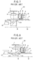
- FIG. 7 shows an example of an optical pickup device having a conventional structure mentioned above.
- a drive coil 3 comprising a focus coil 2 and a tracking coil is mounted to a lens holder 4, which is supported in a cantilevered manner to a suspension support member 6 secured to a yoke base 7 through a suspension member 5 consisting of four fine metal wires, and according to this arrangement, the lens holder 4 is supported in a floating manner as shown in FIG. 7.
- the yoke base 7 has an upper, as viewed, surface to which is secured a yoke 9 having a pair of rising pieces, to one of which a magnet 8 is mounted.
- the magnet 8 and yoke 9 constitute a magnetic circuit adapted to apply a magnetic flux to the drive coil mentioned above.
- the yoke base 7 is formed with a circular hole through which the light beam from a body 10 passes, and a plurality of protruded pieces 7x, each having a spherical surface, are formed around the circular hole.
- an objective lens drive unit 30 is constituted by the lens holder 4, the suspension member 5, the suspension support member 6, the yoke base 7, etc.
- the body 10 has an inner hollow portion in which an optical unit 13, including a light source, a beam splitter and an optical detector, and a rise-up mirror 14 adapted to change the direction of and supply the light beam to the objective lens 2.
- An optical unit 13 including a light source, a beam splitter and an optical detector, and a rise-up mirror 14 adapted to change the direction of and supply the light beam to the objective lens 2.
- a plurality of receiving portions 10x, against which the corresponding protruded pieces 7x abut, respectively, are formed to the peripheral portion of the rise-up mirror 14.
- the objective lens drive unit 30 is supported by the body 10 under the condition that the spherical protruded pieces 7x abut against the receiving portions 10x, respectively, and accordingly, the inclination of the objective lens 2 can be adjusted by relatively sliding these spherical protruded portions 7x and receiving portions 10x.
- the thickness of the device in the optical axis direction is larger than the sum of the thicknesses of the lens holder 4, the yoke base 7 and the rise-up mirror 14.
- a relatively large thickness is required for the lens holder 4 because the drive coil 3 is secured to the lens holder 4, and a relatively large mass is also required for the rise-up mirror 14 in order to surely guide the beam to the objective lens. According to such requirements, it is difficult for the conventional structure to make thin the optical pickup device.
- FIG. 8 Another optical pickup device of conventional structure for solving the above problem is shown in FIG. 8, in which like reference numerals are added to elements corresponding to those shown in FIG. 7.
- the lens holder 4 has a portion to which the objective lens 2 is secured, and the portion has a thickness thinner than that of a portion to which the drive coil 3 is secured. According to this structure, since the rise-up mirror 14 is arranged near the objective lens 2, thus reducing the thickness of the pickup device, in comparison with the structure of FIG. 7.
- Document D1 PATENT ABSTRACTS OF JAPAN vol. 018, no. 172 (P-1715), 23 March 1994 & JP-A-05 334684 (SONY CORP), 17 December 1993
- the actuator base is slidably supported by a body and is adjustable in angular directions.
- the body comprises the laser diode and other optical components.
- Angular adjustment is performed by an adjustment screw which is screwed into the actuator base, while the actuator base is pressed against a spring-plate.
- Sliding is performed by a ball-shaped form of an actuator base portion, fitting into a hole of the body. Because this ball-shaped sliding area is relatively small, the adjusting position is not very stable.
- the present invention seeks to substantially alleviate defects or drawbacks encountered in the prior art described above and to provide an optical pickup device having a thin structure particularly provided with an adjusting mechanism capable of effectively adjusting an inclination of an optical axis.
- the present invention therefore provides an optical pick up device as set out in claim 1.
- the actuator base is further provided with a connecting portion connecting the first and second flat portions.
- the central portions of the spherical end surfaces of the first and second protruded pieces will preferably accord with an optical principal point of the objective lens.
- the adjusting mechanism can comprise screws engaging the actuator base and the body.
- the first and second receiving portions preferably provide flat receiving surfaces against which the spherical end surfaces of the first and second protruded pieces abut.
- the first and second receiving portions can be formed as recessed portions having recessed spherical surfaces against which the spherical end surfaces of the first and second protruded pieces abut.
- the spherical end surface of the first protruded piece will then preferably have a curvature smaller or larger than that of the first receiving portion.
- the optical pickup device comprises an objective lens driving means supporting an objective lens in a floating manner so that the objective lens faces a surface of an optical disk; and a body from which a light beam is projected towards the objective lens
- the objective lens driving means comprises an actuator base and an objective lens holder supported in a floating manner with respect to the actuator base, the actuator base being provided with a first flat portion positioned in a vicinity of the optical disk surface, a second flat portion apart from the optical disk surface, and an oblique connecting portion connecting the first and second flat portions, said first flat portion being formed with a through hole through which the light beam passes and the second flat portion being formed with a magnetic circuit
- said objective lens holder is composed of a thin thickness portion holding the objective lens and a portion, thicker than the thin portion, holding a drive coil applied with magnetic flux by the magnetic coil in which the objective lens holder is supported in a floating manner so that thin portion faces the first flat portion and the thicker portion faces the second flat portion
- the body is composed of a first supporting
- the first and second flat portions are formed with first and second protruded pieces having spherical distal end surfaces, respectively, the first and second supporting portions being formed with first and second receiving portions against which the first and second protruded pieces abut, respectively, the first spherical distal end surface having a curvature different from that of the second spherical distal end surface and wherein an inclination of the objective lens by relatively sliding the first and second protruded portions with respect to the first and second receiving portions in abutting manner.
- the first and second receiving portions can then provide flat receiving surfaces against which the spherical end surfaces of the first and second protruded pieces abut.
- the first and second receiving portions are preferably formed as recessed portions having recessed spherical surfaces against which the spherical end surfaces of the first and second protruded pieces abut.
- the spherical end surface of said first protruded piece will then preferably have a curvature smaller or larger than that of said first receiving portion.
- the inclination of the objective lens is preferably adjustable by means of screws engaging said actuator base and said body.
- the member for reflecting the light beam is suitably a rise-up mirror reflecting the light beam parallel to the disk surface to the light beam vertical thereto.
- the respective protruded pieces having the spherical end surfaces are disposed so that the central portion of the spherical surfaces are near the objective lens, and accordingly, the inclination of the optical axis of the objective lens can be adjusted without changing the distance between the objective lens and the disk surface even in a case where the distances between the objective lens and the respective protruded pieces are different.
- the entire structure of the optical pickup device can be made compact without obstructing the light beam path by the actuator base.
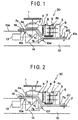
- FIG. 1 shows a whole structure of an optical pickup device for recording or reproducing information on or from an optical disk 1, which basically comprises elements or members similar to those of the device shown in FIG. 7 or 8.
- the lens holder 4 has a portion 4a having a thin thickness in a direction perpendicular to the surface of the disk 1 and a portion 4b having a thickness larger than that of the portion 4a.
- the objective lens 2 is mounted to the thin thickness portion 4a and the drive coil 3 is mounted to the thicker portion 4b.
- the lens holder 4 is connected to the suspension support member 6 secured to the yoke base 7 through the suspension member 5 composed of four fine metal wires to thereby support the lens holder 4 to be movable in a floating manner.
- the yoke base 7 constituting an actuator base has a plate-like bent structure having a first flat portion 7a located near the surface of the disk 1, a second flat portion 7b apart from the disk surface and an intermediate connection portion 7c connecting the first and second flat portions 7a and 7b so as to provide a stepped structure as shown in FIG. 1 as a side view.
- the first flat portion 7a is located to a portion facing the thin thickness portion 4a of the lens holder 4 and provided with a circular hole 7f through which a light beam from the body 10 passes.
- a first spherical protruded piece 7d is formed to the lower surface of the first flat portion 7a so as to extend downward.
- the second flat portion 7b is located to a portion facing the portion 4b of the lens holder 4.
- a magnetic circuit composed of the suspension member 6, the magnet 8 and the yoke 9 is mounted to the upper surface of the second flat portion 7b, and the magnetic circuit itself has a structure similar to the conventional structure.
- a second spherical protruded piece 7e is formed to the lower surface of the second flat portion 7a so as to extend downward.
- two second spherical protruded pieces 7e are located at symmetric positions.
- the optical unit 13 comprises a light source, a beam splitter and an optical detector, and the rise-up mirror 14 for reflecting the light beam from the optical unit 13 and collecting it on the objective lens 2 are provided to the body 10.
- the rise-up mirror 14 is positioned directly below the first flat portion 7a of the yoke base 7.
- the body 10 has a first support portion 10a supporting the first flat portion 7a of the yoke base 7 and a second support portion 10b supporting the second flat portion 7b, both portions 10a and 10b being disposed in the vicinity of the rise-up mirror 14, in which the first support portion 10a is positioned near the disk 1 in comparison with the second support portion 10b.
- the first support portion 10a is formed with a first receiving portion 10c against which the first spherical protruded piece 7d abuts
- the second support portion 10b is formed with a second receiving portion 10d against which the second spherical protruded pieces 7e abut.
- the first flat portion 7a of the yoke base 7 is supported by the first support portion 10a of the body 10 at a portion apart from the light beam path between the optical unit 13 and the rise-up mirror 14 so that the light beam path is not interfered with the yoke base 7.
- the objective lens drive unit 30 is supported by the body 10 in a manner such that the first spherical protruded piece 7d abuts against the first receiving portion 10c and the second spherical protruded pieces 7e abut against the second receiving portion 10d. According to such structure, when these abutting surfaces are relatively slid to each other, the inclination of the objective lens 2 can be adjusted.
- reference numerals 19 and 20 denote adjusting screws which engages the body 10 and the yoke base 7, and the respective spherical protruded pieces are slid through the adjustment of the screws 19 and 20, whereby the inclination of the objective lens 2 can be adjusted.
- the first and second protruded pieces 7d and 7e are designed so that the centers of the spherical surfaces thereof accord with the optical principal point of the objective lens 2 and that the curvatures of these spherical protruded pieces are different from each other. Accordingly, even if the inclination of the objective lens 2 is adjusted by relatively sliding the respective spherical protruded pieces and the corresponding receiving portions, the distance between the disk 1 and the objective lens 2 can be always maintained constant.
- FIG. 2 represents a second embodiment of the present invention, in which a first spherical recessed portion 10e, corresponding in its shape to the first spherical protruded piece 7d is formed to the first support portion 10a in place of the first receiving portion 10c in the first embodiment, and a second spherical recessed portion 10f, corresponding in its shape to the second spherical piece 7e is formed to the second support portion 10b in place of the second receiving portion 10d in the first embodiment.
- the relative sliding motion between the spherical protruded pieces and the spherical recessed portions can be done with high performance.
- FIG. 4 shows a state in which the first receiving portion 10c, against which the first spherical protruded piece 7d formed to the yoke base 7 abuts, is formed so as to provide a flat surface. According to this example, the surface working to the receiving portion can be easily done, thus being advantageous.
- FIG. 5 shows a state in which the curvature of the spherical end surface of the first spherical protruded piece 7d formed to the yoke base 7 is made smaller than the curvature of the spherical surface of the first receiving portion 10c against which the protruded piece 7d abuts. According to this example, a good sliding performance can be achieved even if a working error to the spherical protruded piece 7d exists, and a range for inclination allowance of the objective lens can be made wide.
- FIG. 6 shows a modification of the first receiving portion.
- the first receiving portion 10c is replaced with a protruding portion 10c' to abut against and support the first spherical protruded piece 7d.
- the curvature of the spherical front surface of the first spherical protruded piece 7d formed to the yoke base 7 is made larger than the curvature of the spherical surface of the protruding portion 10c' against which the protruded piece 7d abuts.
- a range for inclination allowance of the objective lens can be made wide like the example of FIG. 5.
- the inclination of the optical axis of the objective lens can be adjusted without changing the distance between the objective lens and the disk surface even in a case where the distances between the objective lens and the respective spherical protruded pieces formed to the yoke base are different. Accordingly, even in a case where the yoke base has a bent structure, the inclination of the objective lens can be effectively adjusted, so that the freedom in design of the objective lens drive unit can be improved and the optical pickup device can be hence made compact and thin.
Description
- The present invention relates to a pickup device for an optical disk adapted to record information on an optical disk or reproduce the information recorded thereon.
- An optical pickup device for recording and reproducing information by irradiating a light beam to an optical disk is well known in the conventional art. Such an optical pickup device is composed of a body, to which an optical system including a light source, a beam splitter and a light detector is mounted, and an objective lens driving unit including an objective lens and a driving means for driving the objective lens. In such an optical pickup device, the light is irradiated from the light source to an optical disk through the objective lens and a light reflected from the optical disk is received by the light detector through the objective lens to thereby record or reproduce the information. Further, the optical pickup device of this type is also provided with a mechanism for freely adjusting an inclination of the objective lens with respect to a disk surface for correctly performing the recording and reproducing of the information.
- FIG. 7 shows an example of an optical pickup device having a conventional structure mentioned above. With reference to FIG. 7, a
drive coil 3 comprising afocus coil 2 and a tracking coil is mounted to alens holder 4, which is supported in a cantilevered manner to asuspension support member 6 secured to ayoke base 7 through asuspension member 5 consisting of four fine metal wires, and according to this arrangement, thelens holder 4 is supported in a floating manner as shown in FIG. 7. Theyoke base 7 has an upper, as viewed, surface to which is secured ayoke 9 having a pair of rising pieces, to one of which amagnet 8 is mounted. Accordingly, themagnet 8 andyoke 9 constitute a magnetic circuit adapted to apply a magnetic flux to the drive coil mentioned above. Theyoke base 7 is formed with a circular hole through which the light beam from abody 10 passes, and a plurality ofprotruded pieces 7x, each having a spherical surface, are formed around the circular hole. As described above, an objectivelens drive unit 30 is constituted by thelens holder 4, thesuspension member 5, thesuspension support member 6, theyoke base 7, etc. - The
body 10 has an inner hollow portion in which anoptical unit 13, including a light source, a beam splitter and an optical detector, and a rise-upmirror 14 adapted to change the direction of and supply the light beam to theobjective lens 2. A plurality of receivingportions 10x, against which the correspondingprotruded pieces 7x abut, respectively, are formed to the peripheral portion of the rise-upmirror 14. - As shown in FIG. 7, the objective
lens drive unit 30 is supported by thebody 10 under the condition that the spherical protrudedpieces 7x abut against the receivingportions 10x, respectively, and accordingly, the inclination of theobjective lens 2 can be adjusted by relatively sliding these spherical protrudedportions 7x and receivingportions 10x. - In the arrangement of the conventional optical pickup device shown in FIG. 7, since the center of the radius of each of the spherical protruded
portions 7x is set so that it accords with an optical principal point of theobjective lens 2, the distance between the surface of thedisk 1 and theobjective lens 2 is maintained constant even if theprotruded pieces 7x and thereceiving portions 10x are relatively slid for adjusting the inclination of theobjective lens 2. - As can be seen from FIG. 7, in the conventional optical pickup device, the thickness of the device in the optical axis direction (direction perpendicular to the disk surface) is larger than the sum of the thicknesses of the
lens holder 4, theyoke base 7 and the rise-upmirror 14. In such arrangement of the conventional structure, a relatively large thickness is required for thelens holder 4 because thedrive coil 3 is secured to thelens holder 4, and a relatively large mass is also required for the rise-upmirror 14 in order to surely guide the beam to the objective lens. According to such requirements, it is difficult for the conventional structure to make thin the optical pickup device. - Another optical pickup device of conventional structure for solving the above problem is shown in FIG. 8, in which like reference numerals are added to elements corresponding to those shown in FIG. 7.
- Referring to FIG. 8, the
lens holder 4 has a portion to which theobjective lens 2 is secured, and the portion has a thickness thinner than that of a portion to which thedrive coil 3 is secured. According to this structure, since the rise-upmirror 14 is arranged near theobjective lens 2, thus reducing the thickness of the pickup device, in comparison with the structure of FIG. 7. - However, in the structure of FIG. 8, since the
end portion 7a of theyoke base 7 is positioned near a portion between the rise-upmirror 14 and theoptical unit 13, it is required that theoptical unit 13 is set so that the light passage of the light beam from theoptical unit 13 is formed without being interfered with theend portion 7a of theyoke base 7, resulting in restriction of the arrangement of theoptical unit 13. - Document D1 (PATENT ABSTRACTS OF JAPAN vol. 018, no. 172 (P-1715), 23 March 1994 & JP-A-05 334684 (SONY CORP), 17 December 1993) which is used for defining the preamble of
independent claim 1, describes an optical pickup device comprising an actuator base supporting an objective lens. The actuator base is slidably supported by a body and is adjustable in angular directions. The body comprises the laser diode and other optical components. Angular adjustment is performed by an adjustment screw which is screwed into the actuator base, while the actuator base is pressed against a spring-plate. Sliding is performed by a ball-shaped form of an actuator base portion, fitting into a hole of the body. Because this ball-shaped sliding area is relatively small, the adjusting position is not very stable. - The present invention seeks to substantially alleviate defects or drawbacks encountered in the prior art described above and to provide an optical pickup device having a thin structure particularly provided with an adjusting mechanism capable of effectively adjusting an inclination of an optical axis.
- The present invention therefore provides an optical pick up device as set out in
claim 1. - In preferred embodiments, the actuator base is further provided with a connecting portion connecting the first and second flat portions.
- The central portions of the spherical end surfaces of the first and second protruded pieces will preferably accord with an optical principal point of the objective lens.
- The adjusting mechanism can comprise screws engaging the actuator base and the body.
- The first and second receiving portions preferably provide flat receiving surfaces against which the spherical end surfaces of the first and second protruded pieces abut. The first and second receiving portions can be formed as recessed portions having recessed spherical surfaces against which the spherical end surfaces of the first and second protruded pieces abut. The spherical end surface of the first protruded piece will then preferably have a curvature smaller or larger than that of the first receiving portion.
- It is further preferred that the optical pickup device comprises an objective lens driving means supporting an objective lens in a floating manner so that the objective lens faces a surface of an optical disk; and a body from which a light beam is projected towards the objective lens, wherein the objective lens driving means comprises an actuator base and an objective lens holder supported in a floating manner with respect to the actuator base, the actuator base being provided with a first flat portion positioned in a vicinity of the optical disk surface, a second flat portion apart from the optical disk surface, and an oblique connecting portion connecting the first and second flat portions, said first flat portion being formed with a through hole through which the light beam passes and the second flat portion being formed with a magnetic circuit, and said objective lens holder is composed of a thin thickness portion holding the objective lens and a portion, thicker than the thin portion, holding a drive coil applied with magnetic flux by the magnetic coil in which the objective lens holder is supported in a floating manner so that thin portion faces the first flat portion and the thicker portion faces the second flat portion, and wherein the body is composed of a first supporting portion for supporting the first flat portion, a second supporting portion for supporting the second flat portion and an intermediate portion disposed below the through hole formed to the first flat portion, and a member disposed to the intermediate portion of the body for reflecting the light beam from a light beam source towards the optical disk surface through the through hole and the objective lens.
- In a preferred embodiment, the first and second flat portions are formed with first and second protruded pieces having spherical distal end surfaces, respectively, the first and second supporting portions being formed with first and second receiving portions against which the first and second protruded pieces abut, respectively, the first spherical distal end surface having a curvature different from that of the second spherical distal end surface and wherein an inclination of the objective lens by relatively sliding the first and second protruded portions with respect to the first and second receiving portions in abutting manner. The first and second receiving portions can then provide flat receiving surfaces against which the spherical end surfaces of the first and second protruded pieces abut.
- The first and second receiving portions are preferably formed as recessed portions having recessed spherical surfaces against which the spherical end surfaces of the first and second protruded pieces abut. The spherical end surface of said first protruded piece will then preferably have a curvature smaller or larger than that of said first receiving portion.
- The inclination of the objective lens is preferably adjustable by means of screws engaging said actuator base and said body.
- The member for reflecting the light beam is suitably a rise-up mirror reflecting the light beam parallel to the disk surface to the light beam vertical thereto.
- According to the preferred embodiments of the present invention described above, the respective protruded pieces having the spherical end surfaces are disposed so that the central portion of the spherical surfaces are near the objective lens, and accordingly, the inclination of the optical axis of the objective lens can be adjusted without changing the distance between the objective lens and the disk surface even in a case where the distances between the objective lens and the respective protruded pieces are different.
- Since the portion of the lens holder at which the objective lens is supported is made thin in thickness and the reflecting member is disposed directly below the thin portion, the entire structure of the optical pickup device can be made compact without obstructing the light beam path by the actuator base.
- The nature and further features of the optical pickup device of the present invention will be made more clear from the following descriptions of preferred embodiments made with reference to the following drawings;
- FIG. 1 is a schematic side view of a first embodiment of an optical pickup device according to the present invention;
- FIG. 2 is a schematic side view of a second embodiment of an optical pickup device according to the present invention;
- FIG. 3 is a plan view of a yoke base of the optical pickup device of the present invention;
- FIG. 4 is a view, in an enlarged scale, showing one example of a structural relationship between a yoke base and a body, in an abutting state, of the optical pickup device of the present invention;
- FIG. 5 is a view, in an enlarged scale, showing another example of a structural relationship between a yoke base and a body, in an abutting state, of the optical pickup device of the present invention;
- FIG. 6 is a view, in an enlarged scale, showing a further example of a structural relationship between a yoke base and a body, in an abutting state, of the optical pickup device of the present invention;
- FIG. 7 is a schematic side view of one example of an optical pickup device of a conventional structure; and
- FIG. 8 is a schematic side view of another example of an optical pickup device of a conventional structure.
-
- In the followings, it is first to be noted that like reference numerals are added to elements or members of embodiments of the present invention corresponding to those of the conventional structures shown in FIGs. 7 and 8.
- FIG. 1 shows a whole structure of an optical pickup device for recording or reproducing information on or from an
optical disk 1, which basically comprises elements or members similar to those of the device shown in FIG. 7 or 8. - According to the structure of FIG. 1, the
lens holder 4 has aportion 4a having a thin thickness in a direction perpendicular to the surface of thedisk 1 and aportion 4b having a thickness larger than that of theportion 4a. Theobjective lens 2 is mounted to thethin thickness portion 4a and thedrive coil 3 is mounted to thethicker portion 4b. Thelens holder 4 is connected to thesuspension support member 6 secured to theyoke base 7 through thesuspension member 5 composed of four fine metal wires to thereby support thelens holder 4 to be movable in a floating manner. - The
yoke base 7 constituting an actuator base has a plate-like bent structure having a firstflat portion 7a located near the surface of thedisk 1, a secondflat portion 7b apart from the disk surface and anintermediate connection portion 7c connecting the first and secondflat portions flat portion 7a is located to a portion facing thethin thickness portion 4a of thelens holder 4 and provided with acircular hole 7f through which a light beam from thebody 10 passes. A first spherical protrudedpiece 7d is formed to the lower surface of the firstflat portion 7a so as to extend downward. The secondflat portion 7b is located to a portion facing theportion 4b of thelens holder 4. A magnetic circuit composed of thesuspension member 6, themagnet 8 and theyoke 9 is mounted to the upper surface of the secondflat portion 7b, and the magnetic circuit itself has a structure similar to the conventional structure. A secondspherical protruded piece 7e is formed to the lower surface of the secondflat portion 7a so as to extend downward. - With reference to FIG. 3 showing a plan view of the
yoke base 7, two second spherical protrudedpieces 7e are located at symmetric positions. - As mentioned with respect to the conventional structure of FIG. 7 or 8, the
optical unit 13 comprises a light source, a beam splitter and an optical detector, and the rise-up mirror 14 for reflecting the light beam from theoptical unit 13 and collecting it on theobjective lens 2 are provided to thebody 10. The rise-up mirror 14 is positioned directly below the firstflat portion 7a of theyoke base 7. - The
body 10 has afirst support portion 10a supporting the firstflat portion 7a of theyoke base 7 and asecond support portion 10b supporting the secondflat portion 7b, bothportions up mirror 14, in which thefirst support portion 10a is positioned near thedisk 1 in comparison with thesecond support portion 10b. Thefirst support portion 10a is formed with afirst receiving portion 10c against which the firstspherical protruded piece 7d abuts, and thesecond support portion 10b is formed with asecond receiving portion 10d against which the second spherical protrudedpieces 7e abut. According to this structure, the firstflat portion 7a of theyoke base 7 is supported by thefirst support portion 10a of thebody 10 at a portion apart from the light beam path between theoptical unit 13 and the rise-up mirror 14 so that the light beam path is not interfered with theyoke base 7. - Further with reference to FIG. 1, the objective
lens drive unit 30 is supported by thebody 10 in a manner such that the firstspherical protruded piece 7d abuts against the first receivingportion 10c and the second spherical protrudedpieces 7e abut against thesecond receiving portion 10d. According to such structure, when these abutting surfaces are relatively slid to each other, the inclination of theobjective lens 2 can be adjusted. In FIG. 1,reference numerals body 10 and theyoke base 7, and the respective spherical protruded pieces are slid through the adjustment of thescrews objective lens 2 can be adjusted. - In this embodiment, the first and second protruded
pieces objective lens 2 and that the curvatures of these spherical protruded pieces are different from each other. Accordingly, even if the inclination of theobjective lens 2 is adjusted by relatively sliding the respective spherical protruded pieces and the corresponding receiving portions, the distance between thedisk 1 and theobjective lens 2 can be always maintained constant. - FIG. 2 represents a second embodiment of the present invention, in which a first spherical recessed
portion 10e, corresponding in its shape to the firstspherical protruded piece 7d is formed to thefirst support portion 10a in place of the first receivingportion 10c in the first embodiment, and a second spherical recessedportion 10f, corresponding in its shape to the secondspherical piece 7e is formed to thesecond support portion 10b in place of thesecond receiving portion 10d in the first embodiment. According to this second embodiment, the relative sliding motion between the spherical protruded pieces and the spherical recessed portions can be done with high performance. - The relative relationships in the surface shapes between the respective spherical protruded pieces and receiving portions will be described hereunder with reference to FIGs. 4 to 6.
- FIG. 4 shows a state in which the first receiving
portion 10c, against which the firstspherical protruded piece 7d formed to theyoke base 7 abuts, is formed so as to provide a flat surface. According to this example, the surface working to the receiving portion can be easily done, thus being advantageous. - FIG. 5 shows a state in which the curvature of the spherical end surface of the first
spherical protruded piece 7d formed to theyoke base 7 is made smaller than the curvature of the spherical surface of the first receivingportion 10c against which the protrudedpiece 7d abuts. According to this example, a good sliding performance can be achieved even if a working error to thespherical protruded piece 7d exists, and a range for inclination allowance of the objective lens can be made wide. - FIG. 6 shows a modification of the first receiving portion. As seen, the first receiving
portion 10c is replaced with a protrudingportion 10c' to abut against and support the firstspherical protruded piece 7d. The curvature of the spherical front surface of the firstspherical protruded piece 7d formed to theyoke base 7 is made larger than the curvature of the spherical surface of the protrudingportion 10c' against which the protrudedpiece 7d abuts. According to this example, a range for inclination allowance of the objective lens can be made wide like the example of FIG. 5. - According to the optical pickup device of the present invention, the inclination of the optical axis of the objective lens can be adjusted without changing the distance between the objective lens and the disk surface even in a case where the distances between the objective lens and the respective spherical protruded pieces formed to the yoke base are different. Accordingly, even in a case where the yoke base has a bent structure, the inclination of the objective lens can be effectively adjusted, so that the freedom in design of the objective lens drive unit can be improved and the optical pickup device can be hence made compact and thin. In the preferred embodiment, there is provided a structure in which the light beam passage in the body cannot be prevented by the actuator base.
Claims (11)
- An optical pickup device comprising:an objective lens assembly (4) including an objective lens (2) facing a surface of an optical disk (1);an actuator base (7) supporting the objective lens to be movable;a body (10) in which an optical element (13) is accommodated and from which light beam is projected towards the objective lens, said actuator base being supported by said body to be slidable,the device being characterized in thatsaid actuator base being provided with a first flat portion (10a) positioned facing the optical disk surface but spaced therefrom, and a second flat portion (10b) facing the optical disk surface and being spaced further from the optical disk surface, said first and second flat portions being formed with first and second protruded pieces (7d, 7e) having first and second spherical end surfaces, respectively, said body being formed with first and second receiving portions (10c, 10d, 10e, 10f) against which said first and second protruded pieces abut, respectively, said first spherical end surface having a curvature different from that of said second spherical end surface; andmeans (19, 20) for adjusting an inclination of the objective lens by relatively sliding said first and second protruded pieces with respect to said first and second receiving portions in abutting manner.
- An optical pickup device according to claim 1 or claim 2, wherein said actuator base is further provided with a connection portion (7c) connecting said first and second flat portions.
- An optical pickup device according to any preceding claim, wherein central portions of the spherical end surfaces of said first and second protruded pieces accord with an optical principal point of the objective lens.
- An optical pickup device according to any preceding claim, wherein said body is composed of a first supporting portion (10a) for supporting said first flat portion, a second supporting portion (10b) for supporting said second flat portion and an intermediate portion disposed below the first flat portion and wherein means for reflecting the light beam (14) from a light beam source (13) towards the optical disk surface through the objective lens is disposed to the intermediate portion of said body.
- An optical pickup device according to claim 4
said objective lens assembly comprises said actuator base (7) and an objective lens holder supported in a floating manner with respect to said actuator base, furthermore an oblique connection portion (7c) connecting said first and second flat portions, said first flat portion is formed with a through bole through which the light beam passes and said second flat portion being formed with a magnetic circuit (8, 9),
said objective lens holder being composed of a thin thickness portion (4a) holding the objective lens and a portion (4b), thicker than the thin thickness portion, holding a drive coil (3) applied with magnetic flux by the magnetic coil in which said objective lens holder is supported in a floating manner so that thin thickness portion faces said first flat portion and said thicker portion faces said second flat portion. - An optical pickup device according to any one of claims 1 to 5, wherein said first and second receiving portions provide flat receiving surfaces against which the spherical end surfaces of said first and second protruded pieces abut.
- An optical pickup device according to any one of claims 1 to 5, wherein said first and second receiving portions are formed as recessed portions having recessed spherical surfaces against which the spherical end surfaces of said first and second protruded pieces abut.
- An optical pickup device according to claim 7, wherein the spherical end surface of said first protruded piece has a curvature smaller than that of said first receiving portion.
- An optical pickup device according to claim 7, wherein the spherical end surface of said first protruded piece has a curvature larger than that of said first receiving portion.
- An optical pickup device according to any one of claims 1 to 5, wherein the inclination of the objective lens is adjusted by means of screws (19, 20) engaging said actuator base and said body.
- An optical pickup device according to any one of claims 4 to 10, wherein said means for reflecting the light beam is a rise-up mirror (14) reflecting the light beam parallel to the disk surface to the light beam vertical thereto.
Priority Applications (1)
| Application Number | Priority Date | Filing Date | Title |
|---|---|---|---|
| EP01116766A EP1160780B1 (en) | 1995-03-30 | 1996-03-29 | Pickup device for optical disk |
Applications Claiming Priority (3)
| Application Number | Priority Date | Filing Date | Title |
|---|---|---|---|
| JP97941/95 | 1995-03-30 | ||
| JP9794195 | 1995-03-30 | ||
| JP7097941A JPH08273165A (en) | 1995-03-30 | 1995-03-30 | Optical pickup device for optical disk |
Related Child Applications (1)
| Application Number | Title | Priority Date | Filing Date |
|---|---|---|---|
| EP01116766A Division EP1160780B1 (en) | 1995-03-30 | 1996-03-29 | Pickup device for optical disk |
Publications (2)
| Publication Number | Publication Date |
|---|---|
| EP0735528A1 EP0735528A1 (en) | 1996-10-02 |
| EP0735528B1 true EP0735528B1 (en) | 2002-10-09 |
Family
ID=14205703
Family Applications (2)
| Application Number | Title | Priority Date | Filing Date |
|---|---|---|---|
| EP96302198A Expired - Lifetime EP0735528B1 (en) | 1995-03-30 | 1996-03-29 | Pickup device for optical disk |
| EP01116766A Expired - Lifetime EP1160780B1 (en) | 1995-03-30 | 1996-03-29 | Pickup device for optical disk |
Family Applications After (1)
| Application Number | Title | Priority Date | Filing Date |
|---|---|---|---|
| EP01116766A Expired - Lifetime EP1160780B1 (en) | 1995-03-30 | 1996-03-29 | Pickup device for optical disk |
Country Status (4)
| Country | Link |
|---|---|
| US (1) | US5703864A (en) |
| EP (2) | EP0735528B1 (en) |
| JP (1) | JPH08273165A (en) |
| DE (2) | DE69632698T2 (en) |
Families Citing this family (4)
| Publication number | Priority date | Publication date | Assignee | Title |
|---|---|---|---|---|
| JP3547908B2 (en) * | 1996-07-12 | 2004-07-28 | パイオニア株式会社 | Optical pickup |
| EP1108256B1 (en) * | 1999-06-24 | 2008-04-09 | Koninklijke Philips Electronics N.V. | Optical scanning device comprising a lens system with adjustable inclination |
| EP1587077A1 (en) * | 2004-04-15 | 2005-10-19 | Deutsche Thomson-Brandt Gmbh | Device for reproducing and/or recording optical recording media |
| JP2008071392A (en) * | 2006-09-13 | 2008-03-27 | Funai Electric Co Ltd | Tilt adjustment mechanism for objective lens |
Family Cites Families (5)
| Publication number | Priority date | Publication date | Assignee | Title |
|---|---|---|---|---|
| JP2634852B2 (en) * | 1988-05-07 | 1997-07-30 | シャープ株式会社 | Objective lens drive tilt adjustment mechanism |
| JPH02294935A (en) * | 1989-05-09 | 1990-12-05 | Sharp Corp | Inclination adjusting mechanism for objective lens driving device |
| JPH0690803B2 (en) * | 1989-05-22 | 1994-11-14 | パイオニア株式会社 | Method of manufacturing information reader |
| US5157459A (en) * | 1989-08-29 | 1992-10-20 | Asahi Kogaku Kogyo Kabushiki Kaisha | Wave front aberration measuring apparatus |
| JPH05334684A (en) * | 1992-05-28 | 1993-12-17 | Sony Corp | Optical pickup |
-
1995
- 1995-03-30 JP JP7097941A patent/JPH08273165A/en active Pending
-
1996
- 1996-03-29 DE DE69632698T patent/DE69632698T2/en not_active Expired - Fee Related
- 1996-03-29 EP EP96302198A patent/EP0735528B1/en not_active Expired - Lifetime
- 1996-03-29 DE DE69624161T patent/DE69624161T2/en not_active Expired - Fee Related
- 1996-03-29 US US08/623,821 patent/US5703864A/en not_active Expired - Fee Related
- 1996-03-29 EP EP01116766A patent/EP1160780B1/en not_active Expired - Lifetime
Also Published As
| Publication number | Publication date |
|---|---|
| EP0735528A1 (en) | 1996-10-02 |
| DE69624161T2 (en) | 2003-06-12 |
| DE69624161D1 (en) | 2002-11-14 |
| US5703864A (en) | 1997-12-30 |
| EP1160780A3 (en) | 2001-12-19 |
| JPH08273165A (en) | 1996-10-18 |
| EP1160780B1 (en) | 2004-06-09 |
| EP1160780A2 (en) | 2001-12-05 |
| DE69632698T2 (en) | 2005-06-16 |
| DE69632698D1 (en) | 2004-07-15 |
Similar Documents
| Publication | Publication Date | Title |
|---|---|---|
| JP2908677B2 (en) | Objective lens attitude adjustment mechanism for optical pickup | |
| JP2684762B2 (en) | Objective lens drive | |
| JPS59191146A (en) | Optical scanner | |
| US5878017A (en) | Optical recording and/or reproducing apparatus having objective lens adjusting mechanism | |
| US20020021631A1 (en) | Actuator for optical pickup | |
| US5805556A (en) | Optical pickup apparatus having a holographic optical element | |
| EP0735528B1 (en) | Pickup device for optical disk | |
| US6310852B1 (en) | Optical recording/reproducing apparatus | |
| US5463612A (en) | Objective lens drive apparatus used in optical information recording/reproducing apparatus | |
| US5241424A (en) | Fine actuator | |
| JP3875187B2 (en) | Optical pickup device | |
| US6055221A (en) | Galvano-mirror optical head capable of adjusting relative positions | |
| EP0472084A2 (en) | Optical head apparatus | |
| IL139083A (en) | Seek actuator for optical recording | |
| JPH08263848A (en) | Objective lens inclination adjusting mechanism | |
| KR100319857B1 (en) | Optical pickup device | |
| JPH11149662A (en) | Adjusting and attaching structure for optical element | |
| KR0116645Y1 (en) | Optical pick-up structure | |
| JPH11110767A (en) | Optical pickup device | |
| US4868821A (en) | Optical pickup which includes a single objective lens having magnification equal to or greater than 3 and equal to or smaller than 5 | |
| EP1074982A1 (en) | Actuator with bi-axial lens tilt adjustment | |
| JP3687263B2 (en) | Optical information recording / reproducing device | |
| JPH05266503A (en) | Optical head | |
| KR100430266B1 (en) | Actuator of optical pickup | |
| KR940007285B1 (en) | Object lens playing apparatus for optical pick-up |
Legal Events
| Date | Code | Title | Description |
|---|---|---|---|
| PUAI | Public reference made under article 153(3) epc to a published international application that has entered the european phase |
Free format text: ORIGINAL CODE: 0009012 |
|
| AK | Designated contracting states |
Kind code of ref document: A1 Designated state(s): DE FR GB |
|
| 17P | Request for examination filed |
Effective date: 19970325 |
|
| 17Q | First examination report despatched |
Effective date: 20010116 |
|
| GRAG | Despatch of communication of intention to grant |
Free format text: ORIGINAL CODE: EPIDOS AGRA |
|
| GRAG | Despatch of communication of intention to grant |
Free format text: ORIGINAL CODE: EPIDOS AGRA |
|
| GRAH | Despatch of communication of intention to grant a patent |
Free format text: ORIGINAL CODE: EPIDOS IGRA |
|
| GRAH | Despatch of communication of intention to grant a patent |
Free format text: ORIGINAL CODE: EPIDOS IGRA |
|
| GRAA | (expected) grant |
Free format text: ORIGINAL CODE: 0009210 |
|
| AK | Designated contracting states |
Kind code of ref document: B1 Designated state(s): DE FR GB |
|
| REG | Reference to a national code |
Ref country code: GB Ref legal event code: FG4D |
|
| REF | Corresponds to: |
Ref document number: 69624161 Country of ref document: DE Date of ref document: 20021114 |
|
| REG | Reference to a national code |
Ref country code: GB Ref legal event code: 746 Effective date: 20030205 |
|
| ET | Fr: translation filed | ||
| REG | Reference to a national code |
Ref country code: FR Ref legal event code: D6 |
|
| PLBE | No opposition filed within time limit |
Free format text: ORIGINAL CODE: 0009261 |
|
| STAA | Information on the status of an ep patent application or granted ep patent |
Free format text: STATUS: NO OPPOSITION FILED WITHIN TIME LIMIT |
|
| 26N | No opposition filed |
Effective date: 20030710 |
|
| PGFP | Annual fee paid to national office [announced via postgrant information from national office to epo] |
Ref country code: FR Payment date: 20060308 Year of fee payment: 11 |
|
| PGFP | Annual fee paid to national office [announced via postgrant information from national office to epo] |
Ref country code: DE Payment date: 20060323 Year of fee payment: 11 |
|
| PGFP | Annual fee paid to national office [announced via postgrant information from national office to epo] |
Ref country code: GB Payment date: 20060329 Year of fee payment: 11 |
|
| GBPC | Gb: european patent ceased through non-payment of renewal fee |
Effective date: 20070329 |
|
| REG | Reference to a national code |
Ref country code: FR Ref legal event code: ST Effective date: 20071130 |
|
| PG25 | Lapsed in a contracting state [announced via postgrant information from national office to epo] |
Ref country code: DE Free format text: LAPSE BECAUSE OF NON-PAYMENT OF DUE FEES Effective date: 20071002 |
|
| PG25 | Lapsed in a contracting state [announced via postgrant information from national office to epo] |
Ref country code: GB Free format text: LAPSE BECAUSE OF NON-PAYMENT OF DUE FEES Effective date: 20070329 |
|
| PG25 | Lapsed in a contracting state [announced via postgrant information from national office to epo] |
Ref country code: FR Free format text: LAPSE BECAUSE OF NON-PAYMENT OF DUE FEES Effective date: 20070402 |