EP0647583A2 - Apparatus for inspecting sheet materials and conveying device used therefor - Google Patents
Apparatus for inspecting sheet materials and conveying device used therefor Download PDFInfo
- Publication number
- EP0647583A2 EP0647583A2 EP94114774A EP94114774A EP0647583A2 EP 0647583 A2 EP0647583 A2 EP 0647583A2 EP 94114774 A EP94114774 A EP 94114774A EP 94114774 A EP94114774 A EP 94114774A EP 0647583 A2 EP0647583 A2 EP 0647583A2
- Authority
- EP
- European Patent Office
- Prior art keywords
- sheet material
- conveying
- sheet materials
- rollers
- sheet
- Prior art date
- Legal status (The legal status is an assumption and is not a legal conclusion. Google has not performed a legal analysis and makes no representation as to the accuracy of the status listed.)
- Granted
Links
Images


Classifications
-
- B—PERFORMING OPERATIONS; TRANSPORTING
- B65—CONVEYING; PACKING; STORING; HANDLING THIN OR FILAMENTARY MATERIAL
- B65H—HANDLING THIN OR FILAMENTARY MATERIAL, e.g. SHEETS, WEBS, CABLES
- B65H29/00—Delivering or advancing articles from machines; Advancing articles to or into piles
- B65H29/38—Delivering or advancing articles from machines; Advancing articles to or into piles by movable piling or advancing arms, frames, plates, or like members with which the articles are maintained in face contact
- B65H29/40—Members rotated about an axis perpendicular to direction of article movement, e.g. star-wheels formed by S-shaped members
-
- B—PERFORMING OPERATIONS; TRANSPORTING
- B65—CONVEYING; PACKING; STORING; HANDLING THIN OR FILAMENTARY MATERIAL
- B65H—HANDLING THIN OR FILAMENTARY MATERIAL, e.g. SHEETS, WEBS, CABLES
- B65H43/00—Use of control, checking, or safety devices, e.g. automatic devices comprising an element for sensing a variable
Definitions
- the present invention relates to an inspection apparatus for detecting whether collected sheet materials are normal or damaged and true or false and for re-accumulating disposal sheet materials and reuse sheet materials and to also a sheet material conveying device suited to this sheet material inspection apparatus.
- the sheet material inspection apparatus is an apparatus which consecutively takes out collected sheet materials accumulated and fed in at a minute pitch by a take-out unit and thereafter checks whether the sheet materials are normal or damaged and true or false while conveying them on a belt at a high speed.
- the sheet material inspection apparatus determines whether the individual sheet materials are to be disposed of or reusable, thereafter distributes the sheet materials to branched conveying paths and re-accumulates the disposal sheet materials and the reuse sheet materials, separately.
- the sheet materials accumulated as the disposal sheet materials by this apparatus are thereafter shredder-processed.
- a processing speed of the sheet materials in this inspection apparatus is on the order of 20-30 sheet materials/sec, and a conveying velocity is always kept constant at 8 m/s.
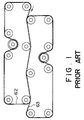
- FIG. 1 illustrates a construction of a sheet material conveying device employed in the conventional sheet material inspection apparatus.
- the transfer of the sheet materials involves independent driving sources and is conducted in such a way that the sheet material is grasped from up and down at two portions in the crosswise direction by flat belts 61, 62 whose conveying surfaces are closely fitted to each other.
- These belts are driven by motors connected to drive rollers.
- Driving the belts at a high speed normally entails an adoption of motors each having a capacity on the order of several hundreds Watt.
- the rollers are disposed alternately on both sides of the conveying path to ensure the close-fitting between the belts.
- the up-and-down belts have a trace of speed-difference, and, hence, a frictional force needs to be applied on both of the belts.
- a resistance of the conveying system is large, and large force is required for driving the belts.
- the belts runs with a trace of oscillations in the crosswise direction, but, because of the surfaces being contact with each other, the belts undergo influences of the oscillations each other. There exists a possibility in which this may causes the belts to come off the rollers.
- the belts always press the upper and lower surfaces of the sheet material, and, consequently, there arises a problem in which the sheet material surface is concealed; and locations for detection are limited.
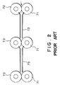
- FIG. 2 depicts a conveying mechanism adopted in the case of conveying sheet materials at a low velocity.
- the sheet material is grasped between drive rollers 71 and rollers 72, and an up-and-down guide 73 is disposed between the rollers. Down-sizing and a reduction in weight in terms of the mechanism are attainable with this system.
- a leading edge of the sheet material is completely free between the guides and therefore collides with the rollers, resulting in an easy-to-damage state.
- a defect is that this system is not suitable for conveying the sheet materials at the high velocity.
- the following problem also arises.
- a dispersion in the driving force between the respective rollers is produced by extrinsic factors such as abrasions, contaminations, etc. on the roller surfaces. This dispersion in the driving force in turn causes a slide, resulting in a difference in the conveying velocity of the sheet material between the respective rollers. As a result, a jam is easy to take place.
- the take-out unit for feeding out the sheet materials to the conveying path is constructed of a holed rotor for performing intermittent rotations and a static chamber connected to a vacuum pump. Every time the rotor stops, the take-out unit absorbs the sheet materials one by one from a stack of sheet materials accumulated and pulls it off the stack of sheet materials. The take-out unit thereafter puts the sheet material into the conveying system at a predetermined sheet material pitch (interval between the leading or trailing edges of the sheet materials fed adjacent to each other). A slight pitch error is produced on the occasion of this take-out operation, and it follows that the sheet materials having a minute pitch error are consecutively fed in the conveying system.
- FIG. 3 schematically illustrates a structure of a sheet material accumulating unit in the prior art sheet material inspection apparatus.
- This sheet material accumulating unit is constructed mainly of an accumulation impeller 71.
- the accumulation impeller 71 is a rotary body having spiral blades at equal intervals with spiral grooves therebetween about the center thereof.
- the impeller 71 is belt-driven by a stepping motor 74.
- the sheet material fed in is stopped upon an insertion into the groove, thereafter scraped out of the groove and thus re-accumulated.
- the sheet materials are then transferred to the next processing.
- the sheet materials fed in have, as stated above, the pitch error. Accordingly, the sheet material accumulating unit is required to absorb this pitch error by use of some means and ensure the insertion of the sheet materials into the accumulation impeller 71. Then, according to the prior art, one point at a groove entrance of the accumulation impeller 71 is defined as an insertion point 75, and the control is effected to make the leading edge of the sheet material reach this insertion point 75.
- a photoelectric sensor 72 is placed in a position across on the conveying path spaced away approximately 1 pitch from the accumulation impeller 71. When sheet material traverses this portion, an output of the sensor changes, thus detecting the leading edge of the sheet material.
- a rotary encoder 73 is connected to a motor 74 for driving the accumulation impeller 71, whereby a position of the in-rotation blade can be detected.
- the sheet material leading edge reaches an optical path of the photoelectric sensor 72 and intercepts a beam of light, and, hereat, the sensor output changes. Then, with this output serving as a trigger, a control unit (not shown) reads a value of the encoder 73 and predicts an insertion position of the relevant sheet material into the groove when the accumulation impeller 71 rotates at a standard rotating speed. At this time, if the sheet material deviates from the insertion point 75 of the groove, the control is carried out to correct this deviation. That is, if the reaching position of the sheet material deviates more forward than the insertion point 75 at the groove entrance, the control unit controls the stepping motor 74 to increase the rotating speed of the accumulation impeller 71.
- the control unit controls the stepping motor 74 to decrease the rotating speed of the accumulation impeller 71.
- the rotating speed of the accumulation impeller 71 is determined to make the sheet material leading edge coincident with the insertion point.
- the rotating speed of the accumulation impeller 71 is varied at all times to correct the pitch error between the respective sheet materials. For this reason, the stepping motor 74 always needs a control torque for an acceleration and a deceleration.
- the sheet material taken out are consecutively fed to the accumulation impeller 71. If the sheet material pitch does not undergo an influence by a disturbance or the like during the feed, however, it follows that the sheet material pitch just after being taken out continue to be kept. On the other hand, since a positional relationship between the blades adjacent to each other is fixed, the grooves of the accumulation impeller 71 can not be properly varied corresponding to the sheet material pitch. Accordingly, if the insertion position is shifted with a change in the rotating speed of the accumulation impeller 71 for an i-th sheet material, this shift directly turns out to be a deviation quantity of the (i+1)-th sheet material with respect to the accumulation impeller 71.
- the insertion position is determined by only the sensor disposed immediately in front of the accumulating unit. Therefore, if the processing speed of the sheet materials is increased, it follows that the control torque needed for the stepping motor for rotating the accumulation impeller augments. This probably results the incapability of control due to the out-of-step of the stepping motor. Accordingly, the processing speed is conditioned by the control torque of the stepping motor, which hinders the speed-up thereof. For this reason, a high-speed and high-torque motor is needed. However, an unreasonable increment in the motor capacity brings about increases in size, in weight and in costs of the apparatus.
- the belts come off. A prevention of this requires a long time for strict adjustments of a belt tension, a roller inclination, etc., and the productivity is not therefore favorable. Also, when conveying the sheet materials t the high velocity, the motor augments in size, and the structure for attaining the down-sizing and the reduction in weight is hard to actualize. The roller conveying system is also easy to damage the sheet materials and therefore unsuitable for the high-speed driving.
- an apparatus for inspecting sheet materials comprising: conveying means for sequentially conveying a plurality of sheet materials; a rotary body, having a plurality of grooves formed in the periphery thereof enough to permit insertions of the sheet materials, for receiving the sheet materials one by one in the respective grooves while rotating the sheet materials fed from said conveying means; accumulating means for accumulating the sheet materials inserted into the grooves of said rotary body; detecting means for detecting a pitch between the sheet materials fed on the conveying unit; and control means for performing control so that the sheet material is inserted from a predetermined position of the groove of said rotary body on the basis of the pitch between the sheet materials that is detected by said detecting means.
- a pitch between the sheet materials to be fed is detected by a plurality of detecting elements provided on a conveying path. Based on this detected pitch between the plurality of sheet materials, a control unit effects the control so that the sheet material is inserted from a predetermined position of a groove of a rotary body (impeller). Even if a pitch deviation is produced when taking out or conveying the subsequent sheet materials, the proper sheet material insertion into the rotary body can be performed by making use of all the data about the sheet material pitches between the individual sheet materials existing on the conveying path ranging from a take-out unit to an accumulating unit.
- a driving system of the rotating the impeller is accelerated or decelerated during a passage of the relevant sheet material on the conveying path of the auxiliary feeding unit. Accordingly, the sheet material is inserted in a predetermined insertion range of the accumulation impeller, thus effecting the control. It is therefore possible to reduce an increment quantity of the control torque of the accumulation impeller.
- auxiliary conveying means of the sheet material inspection apparatus of this invention while referring to the sheet material pitch data, if a sheet material pitch between a certain sheet material and a sheet material just before it is larger or smaller by a fixed quantity than a standard pitch, a driving system of the auxiliary conveying means is accelerated or decelerated during a passage of the relevant sheet material on the conveying path of the auxiliary conveying unit.
- the sheet material pitch between the relevant sheet material and the sheet material just before it is thereby corrected, thus restraining a scatter in terms of the sheet material pitch down to a predetermined quantity or under.
- the sheet material is inserted in a predetermined insertion range of the accumulation impeller, thus effecting the control. It is therefore possible to further reduce an increment quantity of the control torque of the accumulation impeller.
- a sheet material conveying device for conveying sheet materials, having a plurality of conveying unit comprising: a pair of rollers disposed away a predetermined distance from each other; a driving belt stretched between said pairs of rollers and wound on said rollers through a predetermined angle; and a guide member disposed between said pairs of rollers so that its upper surface is located more downward by a predetermined spacing than a conveying surface of the driving belt, said conveying surface being opposed to said rollers, whereby the sheet materials being supported between said driving belt and said guide member and being conveyed with the driving the belt.
- the sheet material conveying device of the present invention has guides disposed in face-to-face relationship with belts wound on feeding rollers but provided at a fixed interval on a belt conveying surface between rollers.
- the feeding rollers are disposed to set the centers of curvatures in the same direction, and, hence, there increases a contact force between the sheet material and the belt increases due to a generation of centrifugal force of the belt by a high-speed feed.
- the sheet material can be therefore fed by an extremely small amount of driving force.
- the number of belts can be decreased in terms of its structure as compared with the example of the prior art, and down-sizing of the mechanism is attainable.
- the belts are driven with a small resistance and can be readily driven at a high speed.
- the belts do not come off, and this eliminates the necessity for adjusting a belt tension, an roller inclination, etc..
- the time for manufacturing and adjusting the apparatus can be reduced so much.
- one side of the sheet material is always pressed against the conveying belt, and consequently there is no possibility to damage the sheet material due to a flip of the sheet material between the rollers.
- a conveying posture correcting (skew) mechanism for the in-feed sheet material can be easily incorporated by taking the present structure, and a more stable feed detection system can be constructed.
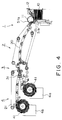
- FIG. 4 is a constructive view illustrating the whole construction of a sheet material inspection apparatus according to the present invention.
- the sheet material inspection apparatus is constructed of a take-out unit 1, a conveying (detecting) unit 2, a separating unit 3 and an accumulating unit 4 that are disposed in sequence.
- Sheet materials 10 are fed in a stacked state into this apparatus by a conveying mechanism which is not shown.
- the sheet materials 10 are separated one by one by a take-out rotor 11 and put into a conveying path constituting a conveying unit 2.
- An unillustrated detecting unit is disposed above the surface of the sheet material 10 on the conveying path 20. The detecting unit checks each of the sheet materials 10 as to whether the sheet material 10 is normal or damaged and true or false.
- the accumulating unit 4 is separated into a reuse sheet material accumulating section 4a and a disposal sheet material accumulating section 4b.
- the sheet materials 10 are distributed in their conveying directions. This distribution is done through a distribution gate 31 provided on the conveying path 20.
- An accumulation impeller 41 is provided on each of the accumulating sections 4a, 4b, thereby receiving but stopping and re-accumulating the sheet materials 10 fed at a high velocity.
- the reuse sheet materials are stacked in a post-processing unit (not shown) and fed out of the present apparatus.
- the disposal sheet materials are sent to a disposal processing unit (shredder, unillustrated).
- Photoelectric sensors for inspecting a passage of the sheet material 10 are provided in several positions on the conveying path 20.
- the photoelectric sensors are employed for checking take-out the sheet material 10, confirming the passage of the sheet material on the conveying path and checking an insertion thereof into the accumulating unit 4 and calculating a pitch of the sheet materials.
- the sheet material pitch implies an interval between the leading or trailing edges of the sheet materials fed adjacent to each other.
- the photoelectric sensor is capable of detecting abnormalities (abnormalities in sheet material length and in sheet material pitch) in the sheet materials 10 on the conveying path 20.
- a photoelectric sensor 51 disposed just behind the take-up roller 11 serves to calculate the sheet material pitch immediately after taking out the sheet materials 10.
- the photoelectric sensor 51 calculates the sheet material pitch, and, if an abnormal pitch is caused, the system quickly detects this abnormality and takes a proper measure.
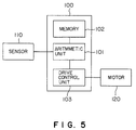
- FIG. 5 is a block diagram illustrating a construction of a control system 100 of the sheet material inspection apparatus according to this invention.
- This microcomputer-based control system 100 includes an arithmetic unit 101 for effecting a variety of arithmetic operations, a memory 102 for storing an item of sheet material pitch data which will be mentioned later.
- the control system also includes a drive control unit 103 for driving a drive motor 120 for a belt or the like on the basis of an arithmetic result given by the arithmetic unit 101.
- Output signals of a variety of sensors 110 are given to this control system, and, after being rearranged in a data format by the arithmetic unit 101, the arithmetic and storing operations are performed.
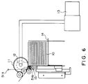
- FIG. 6 depicts a construction of the take-out unit.
- FIG. 6 illustrates how the sheet materials are taken out.
- the take-out roller 11 is a thin-walled roller including a suction hole 16 cut in the peripheral side surface.
- the take-out roller 11 is intermittently driven by driving a gear, a cam or a servo motor so as to temporarily stop in such a position that the suction hole 16 comes to face-to-face relationship with sheet material surface within one rotation.
- a sealed static chamber 12 is accommodated in the interior of the take-out roller 11 but connected to an external vacuum pump 13. An air space within the chamber 12 is kept at a negative pressured with respect to the atmospheric pressure by the vacuum pump 13.
- the sheet material 10 on a sheet material feed board 14 is separated from a stack of sheet materials thereunder and sucked by the suction hole 16 when the take-out roller 11 is stopped (FIG. 7C). Then, when the take-out roller 11 starts rotating (FIG. 7D), the sucked sheet material 10 is raised along the side surface of the rotor, and the leading edge thereof is inserted into the conveying path. Hereat, the sheet material is separated unchanged from the side surface of the rotor and then fed.
- a stack of sheet materials thereunder may be slightly pulled due to an influence of a frictional force, resulting in a positional deviation.
- the underside of the sheet material passing is sucked feebly by a two-sheet material take-out preventive block 15.
- the second sheet material is herein stopped but not inserted into the conveying unit. At the next take-out timing, this sheet material is sucked by the take-out rotor 11 and then fed.
- FIG. 9 is a timing chart showing how the sheet material pitch is detected.
- the detection of the sheet material pitch involves the use of a timer, wherein a signal of the photoelectric sensor 51 shown in FIG. 4 serves as a trigger. When the leading or trailing edge of the sheet material traverses between the photoelectric sensors 51, sensor outputs change from an H-level to an L-level. However, this signal serves as the trigger, and a timer signal may be taken in.
- An i-th sheet material pitch P i is a time difference between a timer value T i taken in i-th time by the detecting unit and a timer value T i + 1 taken in (i+1)th time.
- the sheet material pitches P i are stored sequentially in the memory.
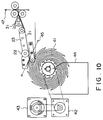
- FIG. 10 schematically illustrates a construction of the accumulating unit.
- the accumulation impeller 41 is rotationally driven by a stepping motor 42.
- a rotary encoder 43 is belt-connected to the motor shaft and works to monitor a rotational position of the accumulation impeller 41, and an encoder output thereof is supplied to the control unit (not shown).
- FIG. 11 shows a construction of the accumulation impeller.
- This accumulation impeller 41 has twelve lines of spiral grooves formed at equi-angles on a cylinder.
- An insertion width of the sheet material into this groove falls within a range of central angles ⁇ 1 - ⁇ 2, wherein fiducial point is the tip of the blade of the accumulation impeller 41.
- a set position of this insertion width is determined in consideration of the sheet material length, a sheet material conveying velocity, the number of groves and a rotating speed of the impeller. Namely: L / V ⁇ (360 / N - ⁇ 2) / W (1) where L is the sheet material length, V is the sheet material conveying velocity, N is the number of groves, and W is the rotating speed of the accumulation impeller.
- a scraping plate 44 is provided on the side surface of the accumulation impeller 41.
- the sheet materials inserted in the accumulation impeller 41 are neatly arranged by the scraping plate 44, and the leading edges thereof fall down along the scraping plate 44 with rotations of the blades, thus re-accumulating the sheet materials.
- An insertion detecting sensor 45 is disposed on the circumference of the accumulation impeller 41.
- This insertion detecting sensor 45 is constructed of a light emitting element and a light receiving element, and its output changes when the sheet material passes by.
- the insertion of the sheet material into the accumulation impeller 41 can be recognized by placing the insertion detecting sensor 45 to traverse the conveying path slightly in front of a point at which the sheet material reaches an entrance of the accumulation impeller 41, i.e., an intersection between the conveying path and a line of outer shape of the accumulation impeller 41.
- An insertion position of the sheet material at a groove entrance of the accumulation impeller 41 can be detected by reading a value of the rotary encoder 43, wherein the output of this insertion detecting sensor 45 serves as a trigger. Items of data about the insertion position and the rotating speed of the accumulation impeller are fed back to the control system. Then, a control characteristic can be also improved by changing a weighing coefficient of an evaluation function which will be stated later.
- FIG. 12 is a flowchart showing a procedure where the control system 100 controls the accumulating unit.
- the accumulating unit is controlled by a signal of the controller.
- the rotating speed of the accumulation impeller is determined by use of data about the sheet material pitches of the sheet materials from the one just before being inserted to the one located a plurality of sheet materials behind. This aims at decreasing a peak of control torque of the stepping motor 42 for driving the accumulation impeller 41, wherein an item of control data is the arrangement of the sheet materials from the one just before the insertion to the one located the plurality of sheet materials behind.
- step S101 the output of the sensor 51 disposed immediately after the take-out roller 11 changes from HIGH to LOW.
- the sheet material pitch Pi is calculated from this fall-to-fall time (step S102).
- i-th and subsequent sheet material pitches Pi, Pi+1, ... are stored in the memory.
- the sheet materials are fed on the conveying path, and the photoelectric sensor 47 (see FIG. 11) provided on the conveying path disposed away approximately 1 pitch on the basis of the standard sheet material pitch from the accumulation impeller 41 detects a passage of the i-th sheet material (step S103).
- the controller causes the encoder 43 to read blade positions of the accumulation impeller 41 and thus determining an insertion position of the i-th sheet material (step S104).
- the target insertion position of this sheet material is a predetermined position within the above-mentioned insertion width.
- the already-stored sheet material pitch is read (step S105), and an arithmetic operation about the evaluation function which will be stated alter is performed (step S106).
- the rotating speed of the accumulation impeller 41 is determined to obtain a proper insertion position (step S107).
- the motor of the impeller is controlled to obtain this rotating speed (step S108). Note that the sheet material pitch data P i between the sheet material finishing its insertion and the sheet material just behind this sheet material are sequentially erased from the memory 102 in order to save the memory capacity.
- the insertion position of the relevant sheet material is determined to reduce a quantity of the pitch deviation of the next sheet material to the greatest possible degree. This makes a large contribution to the reduction in the control torque.
- the evaluation function J expressed by the following equation is obtained, and there is selected such a control quantity as to minimize a value of this evaluation function.
- J (Control Quantity)2 + ⁇ (Sheet material Pitch Scatter Quantity Produced In Consequence of Control)2 (4) Created is a formula in which the parameter in the formula (4) is expressed by the insertion position (insertion angle) into the groove.
- ⁇ i is the insertion position of the i-th sheet material when the accumulation impeller 41 goes on rotating at the standard speed with respect to the insertion width ⁇ e determined by the formula (3) given above. If the insertion position is shifted by ⁇ c due to a fluctuation in the rotating speed, it is required that the following relationship be established: - ⁇ e ⁇ ⁇ i + ⁇ c ⁇ ⁇ e (5)
- the control quantity ⁇ c has to fall within the following range: - ⁇ e - ⁇ i ⁇ ⁇ c ⁇ ⁇ e - ⁇ i (6)
- the each sheet material pitch P i is stored in the memory immediately after being taken out.
- the controller for the accumulating unit is thereby capable of knowing the positions of the i-th sheet material and of the subsequent sheet materials and calculating ⁇ i + 1 , ⁇ i + 2 , ... at that time. Then, these items of data are employed for the control, and the evaluation function Ji for controlling the insertion of the i-th sheet material is expressed such as:
- the second term of the formula (7) intends to weight an influence on the sheet materials posterior to the i-th sheet material. In such a range as to satisfy the formula (6), there is selected such ⁇ c as to minimize Ji in the formula (7). It is thus possible to perform the control ensuring the insertion and taking the subsequent sheet materials into consideration.
- C k in the formula (6) represents the weighing coefficient of the control of the respective sheet materials
- n is the predicted number of sheet materials used for the control.
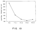
- FIG. 13 is a graphic chart showing effects based on the accumulation control system of the sheet material inspection apparatus according to this invention.
- N.C. Control based on only the positional data of the sheet material just before the insertion.
- F.C.1 Control based on the data about the pitch from the sheet material on the verge of the insertion to the one located one sheet material behind.
- F.C.2 Control based on the data about the pitch from the sheet material on the verge of the insertion to the one located two sheet materials behind.
- F.C.3 Control based on the data about the pitch from the sheet material on the verge of the insertion to the sheet material located three sheet materials behind.
- F.C.4 Control based on the data about the pitch from the sheet material on the verge of the insertion to the one located four sheet materials behind.
- the sheet material inspection apparatus in this embodiment when inserting the sheet material into the accumulation impeller, it is possible to reduce the control torque of the motor for driving the accumulation impeller, and, therefore, a higher-speed feed of the sheet material is attainable.
- FIG. 14 is a schematic view illustrating a construction of the sheet material inspection apparatus in another embodiment of this invention.
- an auxiliary conveying unit 6 including an auxiliary conveying path 61 disposed just behind the take-out unit 1.
- This auxiliary conveying path 61 has a length enough to admit a passage of substantially one sheet material but is driven independently by an AC servo motor 62 separate from the main conveying path.
- the controller performs an acceleration and a deceleration of the auxiliary conveying path 61 on the basis of the pitch data of the sheet material immediately after the take-out unit 1. If the pitch error of the sheet material immediately after the take-out unit 1 comes to a magnitude greater than a predetermined error, the sheet material pitch is corrected by the controller.
- the AC servo motor 62 accelerates (or decelerates) the feed from a point of time when the relevant sheet material reaches the auxiliary conveying path 61, and a pitch error between the i-th sheet material and the sheet material anterior thereto is reduced by a predetermined quantity.
- the pitch correction width Pa is given by the following formula: LD / Vmax - LD / V ⁇ Pa ⁇ LD /Vmin - LD / V (8) where LD is the length of the auxiliary conveying path 61, and V is the standard sheet material conveying velocity.
- the sheet material insertion width converted into the sheet material pitch error of the accumulation impeller is ⁇ 10 % of the standard sheet material pitch
- the sheet material pitch error generated when taken out is ⁇ 30 % of the standard sheet material pitch
- the accumulation impeller may absorb +10 % with fluctuations in the rotating speed when having such a correction capability as to set Pa to +10 % of the standard sheet material pitch in this auxiliary conveying unit 6. If the auxiliary conveying unit 6 does not exist, however, an error on the order of ⁇ 20 % has to be absorbed by the fluctuations in the rotating speed. In this way, the control torque of the stepping motor when controlling the accumulation impeller can be reduced by providing the auxiliary conveying unit 6.
- the sheet materials can be accumulated at the high speed. Further, the sheet materials can be accumulated at a higher speed with a combination of the above-discussed control method of the accumulation impeller according to this invention and the sheet material pitch correction effected by this auxiliary conveying unit.
- FIGS.8A-8C are schematically illustrates a partial construction of one unit (conveying unit) of the conveying mechanism 20.
- FIG. 8A is a plan view.
- FIG. 8B is a front view.
- FIG. 8C is a perspective view.
- the conveying mechanism is constructed of belts 21, rollers 22 and guides 23. Two lengths of belts are provided in parallel to the conveying direction.
- a conveying system is that the sheet material is held at two portions in the crosswise direction of the feed by the belts 21 and the rollers 22 and thus fed.
- the belts 21 are wound on drive rollers (not shown) provided in positions off the conveying surface and thus driven at a high velocity.
- the rollers 22 wound with the belts 21 rotate in idling, whereby the sheet material 10 is fed between the belts 21 and the rollers 22.
- a spacing between the rollers 22 is set smaller than a length of the sheet material in the conveying direction to surely feed the sheet material 10. Leastwise, some portion of the sheet material 10 is always held between the belts 21 and the rollers 22, and the driving is conducted with a stability.
- the guides 23 are disposed at a height enough to give a clearance on the order of 0.5 - 3 mm with respect to the belts 21 but laid in a rail-like configuration in the crosswise direction of the feed sheet material.
- a surface material of the guide 23 involves the use of a resinous material and a polymer material (e.g., polytetrafluoroethylene resin) exhibiting a lubricity, thereby making it possible to reduce a damage on the sheet material 10 due to a contact therebetween. Further, it is also available that the metal-worked guide whose surface is coated with a lubricating material, or a member composed of the lubricating material is bonded thereto.
- a resinous material e.g., polytetrafluoroethylene resin
- the edges of the guide 23 on both sides thereof are notched in a shape of circular arc along the periphery of the roller shaft from the side to the upper portion of the roller shaft.
- the front edge of the guide 23 on the downstream side in the conveying direction is formed with an inclined surface oriented upward of the roller from the guide upper surface. The formation of this inclined surface prevents the sheet material from entering downward of the guide 23.
- the guides are provided in parallel to the belts and assume a configuration adapted to support the sheet material with a minute width, and, therefore, even if a flexure and vibrations of the sheet material in the up-and-down directions are caused during the feed, they do not turn out obstacles against the feed. This effectively prevents a damage on the sheet material 10 particularly during the feed at the high velocity.
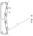
- FIG. 15 is a view fully illustrating a configuration of the conveying path 20 shown in FIG. 3.
- the conveying unit shown in FIGS. 8A-8C is constructed in such a manner that a plurality of rollers thereof are connected on the same circular arc.
- the belt runs to depict an arc having a radius R due to its inertia between the rollers.
- a centrifugal force F in the belt-direction acts on the sheet material.
- FIG. 16 illustrates an example of the configuration of a belt-to-belt receiving/conveying unit in the above-mentioned conveying system in this embodiment.
- the leading end of the conveying belt located downstream is in face-to-face relationship with the proximal portion of the belt located upstream.
- the guide 23 is disposed above the belt 21 on the downstream side but under the belt 21 on the upstream side.
- FIGS. 17A-17C show another example of the conveying unit.
- FIG. 14A is a plan view.
- FIG. 14B is a front view.
- FIG. 14C is a perspective view.
- This conveying system is constructed so that at least one portion of the sheet material in the lengthwise direction is grasped by the belt and the roller, and both edges thereof in the crosswise direction are guided from more outside than the rollers.
- This belt is stretched between two rollers 26, 26.
- Two pieces of guides 23 are provided outward in the crosswise direction of this belt. A shape of this guide is absolutely the same as that explained in FIG. 4.
- the sheet material can be fed at the high velocity.
- FIG. 18 illustrates a combination of the conveying unit shown in FIGS. 17A-17C and the conveying unit shown in FIG. 8.
- This conveying device takes such a construction that the rollers 26, provided upstream and downstream, of the conveying unit shown in FIG. 17 are located between two rollers 27, 27 with respect to the downstream-side belt 21. With this construction, a distance between the roller 27 and the roller 26 can be decreased, and it is therefore possible to actualize the conveying system causing a less amount of jams.
- FIG. 19 illustrates an example where detection units 52, 53, 54 for the sheet materials are disposed along the conveying path according to this invention.
- the rollers are provided concentratedly on one side of the conveying path, and, therefore, a size of the detection system can be considerably freely designed on the side where the rollers do not exist. Hence, there is a small constraint in terms of the size when designing the detection device. Further, the distance to the sheet material can be freely set.
- the same detection device as the conventional one can be basically disposed on the side where the rollers exist.
- the detection device and the guide are formed into one united body, thereby making it possible to perform the detection in close proximity to the sheet material surface.
- FIGS. 20A-20C illustrate a construction of a conveying device 80 in accordance with another embodiment of the present invention.
- FIG. 20A is a plan view.
- FIG. 20B is a front view.
- FIG. 20C is a side view.
- the belt is employed in place of the guide of FIG. 8. That is, the roller in this embodiment is composed of ordinary rollers 81 and roller members 82 each having a small diameter.
- a belt 83 is stretched between the rollers 81 and 81.
- a belt 84 is stretched between the rollers 82 and 82.
- a clearance on the order of 0.5 - 3 mm is provided between the belts 83 and 84. With this arrangement, the belt 84 performs the same function as that of the guide plate explained in FIG. 8.
- the insertion of the sheet material into the impeller is controlled based on the sheet material-to-sheet material pitch.
- the sheet material inspection apparatus capable of performing the accumulating operation at an extremely high velocity without causing the increment in the control torque of the motor for driving the accumulation impeller in the accumulating unit.
- the rollers and the belts cooperate to give the conveying force, and, meanwhile, the sheet material is guided by the guide plates.
- the sheet materials can be thereby stably fed at the high velocity with the simple construction.
Abstract
Description
- The present invention relates to an inspection apparatus for detecting whether collected sheet materials are normal or damaged and true or false and for re-accumulating disposal sheet materials and reuse sheet materials and to also a sheet material conveying device suited to this sheet material inspection apparatus.
- To start with, a conventional sheet material inspection apparatus will be explained.
- The sheet material inspection apparatus is an apparatus which consecutively takes out collected sheet materials accumulated and fed in at a minute pitch by a take-out unit and thereafter checks whether the sheet materials are normal or damaged and true or false while conveying them on a belt at a high speed. The sheet material inspection apparatus then determines whether the individual sheet materials are to be disposed of or reusable, thereafter distributes the sheet materials to branched conveying paths and re-accumulates the disposal sheet materials and the reuse sheet materials, separately. The sheet materials accumulated as the disposal sheet materials by this apparatus are thereafter shredder-processed. A processing speed of the sheet materials in this inspection apparatus is on the order of 20-30 sheet materials/sec, and a conveying velocity is always kept constant at 8 m/s.
- FIG. 1 illustrates a construction of a sheet material conveying device employed in the conventional sheet material inspection apparatus. The transfer of the sheet materials involves independent driving sources and is conducted in such a way that the sheet material is grasped from up and down at two portions in the crosswise direction by
flat belts - As illustrated in FIG. 1, the rollers are disposed alternately on both sides of the conveying path to ensure the close-fitting between the belts. In the case of such a construction, the up-and-down belts have a trace of speed-difference, and, hence, a frictional force needs to be applied on both of the belts. For this purpose, a resistance of the conveying system is large, and large force is required for driving the belts. Further, the belts runs with a trace of oscillations in the crosswise direction, but, because of the surfaces being contact with each other, the belts undergo influences of the oscillations each other. There exists a possibility in which this may causes the belts to come off the rollers. Moreover, the belts always press the upper and lower surfaces of the sheet material, and, consequently, there arises a problem in which the sheet material surface is concealed; and locations for detection are limited.
- FIG. 2 depicts a conveying mechanism adopted in the case of conveying sheet materials at a low velocity. The sheet material is grasped between
drive rollers 71 androllers 72, and an up-and-down guide 73 is disposed between the rollers. Down-sizing and a reduction in weight in terms of the mechanism are attainable with this system. However, a leading edge of the sheet material is completely free between the guides and therefore collides with the rollers, resulting in an easy-to-damage state. A defect is that this system is not suitable for conveying the sheet materials at the high velocity. Furthermore, the following problem also arises. A dispersion in the driving force between the respective rollers is produced by extrinsic factors such as abrasions, contaminations, etc. on the roller surfaces. This dispersion in the driving force in turn causes a slide, resulting in a difference in the conveying velocity of the sheet material between the respective rollers. As a result, a jam is easy to take place. - The take-out unit for feeding out the sheet materials to the conveying path is constructed of a holed rotor for performing intermittent rotations and a static chamber connected to a vacuum pump. Every time the rotor stops, the take-out unit absorbs the sheet materials one by one from a stack of sheet materials accumulated and pulls it off the stack of sheet materials. The take-out unit thereafter puts the sheet material into the conveying system at a predetermined sheet material pitch (interval between the leading or trailing edges of the sheet materials fed adjacent to each other). A slight pitch error is produced on the occasion of this take-out operation, and it follows that the sheet materials having a minute pitch error are consecutively fed in the conveying system.
- FIG. 3 schematically illustrates a structure of a sheet material accumulating unit in the prior art sheet material inspection apparatus. This sheet material accumulating unit is constructed mainly of an
accumulation impeller 71. Theaccumulation impeller 71 is a rotary body having spiral blades at equal intervals with spiral grooves therebetween about the center thereof. Theimpeller 71 is belt-driven by astepping motor 74. The sheet material fed in is stopped upon an insertion into the groove, thereafter scraped out of the groove and thus re-accumulated. The sheet materials are then transferred to the next processing. - Herein, for preventing a damage of the sheet material due to a jam and a collision with a blade, there is necessity for assuring that only one sheet material be surely inserted into one line of groove. That is, the sheet materials fed in have, as stated above, the pitch error. Accordingly, the sheet material accumulating unit is required to absorb this pitch error by use of some means and ensure the insertion of the sheet materials into the
accumulation impeller 71. Then, according to the prior art, one point at a groove entrance of theaccumulation impeller 71 is defined as aninsertion point 75, and the control is effected to make the leading edge of the sheet material reach thisinsertion point 75. - Given next is an explanation of a control method of the accumulating unit in the conventional sheet material inspection apparatus.
- A
photoelectric sensor 72 is placed in a position across on the conveying path spaced away approximately 1 pitch from theaccumulation impeller 71. When sheet material traverses this portion, an output of the sensor changes, thus detecting the leading edge of the sheet material. Arotary encoder 73 is connected to amotor 74 for driving theaccumulation impeller 71, whereby a position of the in-rotation blade can be detected. - The sheet material leading edge reaches an optical path of the
photoelectric sensor 72 and intercepts a beam of light, and, hereat, the sensor output changes. Then, with this output serving as a trigger, a control unit (not shown) reads a value of theencoder 73 and predicts an insertion position of the relevant sheet material into the groove when theaccumulation impeller 71 rotates at a standard rotating speed. At this time, if the sheet material deviates from theinsertion point 75 of the groove, the control is carried out to correct this deviation. That is, if the reaching position of the sheet material deviates more forward than theinsertion point 75 at the groove entrance, the control unit controls thestepping motor 74 to increase the rotating speed of theaccumulation impeller 71. In the reverse case, the control unit controls the steppingmotor 74 to decrease the rotating speed of theaccumulation impeller 71. In any case, the rotating speed of theaccumulation impeller 71 is determined to make the sheet material leading edge coincident with the insertion point. Thus arithmetic operation is performed each time the sheet material reaches the position of thephotoelectric sensor 72. The rotating speed of theaccumulation impeller 71 is varied at all times to correct the pitch error between the respective sheet materials. For this reason, thestepping motor 74 always needs a control torque for an acceleration and a deceleration. - The sheet material taken out are consecutively fed to the
accumulation impeller 71. If the sheet material pitch does not undergo an influence by a disturbance or the like during the feed, however, it follows that the sheet material pitch just after being taken out continue to be kept. On the other hand, since a positional relationship between the blades adjacent to each other is fixed, the grooves of theaccumulation impeller 71 can not be properly varied corresponding to the sheet material pitch. Accordingly, if the insertion position is shifted with a change in the rotating speed of theaccumulation impeller 71 for an i-th sheet material, this shift directly turns out to be a deviation quantity of the (i+1)-th sheet material with respect to theaccumulation impeller 71. That is, depending on the way how the sheet material pitch is scattered, if only the insertion position of the just-before sheet material is considered, the deviation quantity with respect to the sheet material subsequent thereto becomes excessive, As a result, a control quantity of theaccumulation impeller 71, i.e., a control torque of the motor, becomes excessive, and hence there is a possibility of being incapable of control due to the fact that the motor is out of step. Particularly when speeding up the apparatus, this problem turns out a large obstacle. - In the prior art sheet material inspection apparatus, the insertion position is determined by only the sensor disposed immediately in front of the accumulating unit. Therefore, if the processing speed of the sheet materials is increased, it follows that the control torque needed for the stepping motor for rotating the accumulation impeller augments. This probably results the incapability of control due to the out-of-step of the stepping motor. Accordingly, the processing speed is conditioned by the control torque of the stepping motor, which hinders the speed-up thereof. For this reason, a high-speed and high-torque motor is needed. However, an unreasonable increment in the motor capacity brings about increases in size, in weight and in costs of the apparatus.
- Furthermore, in the sheet material inspection apparatus using the conventional belts, it may happen that the belts come off. A prevention of this requires a long time for strict adjustments of a belt tension, a roller inclination, etc., and the productivity is not therefore favorable. Also, when conveying the sheet materials t the high velocity, the motor augments in size, and the structure for attaining the down-sizing and the reduction in weight is hard to actualize. The roller conveying system is also easy to damage the sheet materials and therefore unsuitable for the high-speed driving.
- Under such circumstances, it is a primary object of the present invention to provide a sheet material inspection apparatus capable of a high-speed accumulation without increasing a control torque of a motor for driving an accumulation impeller.
- It is another object of the present invention to provide a sheet material conveying device in which the sheet material is hard to damage with a simple structure.
- According to the present invention, there is provided an apparatus for inspecting sheet materials, comprising:
conveying means for sequentially conveying a plurality of sheet materials;
a rotary body, having a plurality of grooves formed in the periphery thereof enough to permit insertions of the sheet materials, for receiving the sheet materials one by one in the respective grooves while rotating the sheet materials fed from said conveying means;
accumulating means for accumulating the sheet materials inserted into the grooves of said rotary body;
detecting means for detecting a pitch between the sheet materials fed on the conveying unit; and
control means for performing control so that the sheet material is inserted from a predetermined position of the groove of said rotary body on the basis of the pitch between the sheet materials that is detected by said detecting means. - In the sheet material inspection apparatus according to this invention, a pitch between the sheet materials to be fed is detected by a plurality of detecting elements provided on a conveying path. Based on this detected pitch between the plurality of sheet materials, a control unit effects the control so that the sheet material is inserted from a predetermined position of a groove of a rotary body (impeller). Even if a pitch deviation is produced when taking out or conveying the subsequent sheet materials, the proper sheet material insertion into the rotary body can be performed by making use of all the data about the sheet material pitches between the individual sheet materials existing on the conveying path ranging from a take-out unit to an accumulating unit.
- According to an embodiment of adopting a control of rotating speed of the impeller, while referring to the sheet material pitch data, if a sheet material pitch between a certain sheet material and a sheet material just before it is larger or smaller by a fixed quantity than a standard pitch, a driving system of the rotating the impeller is accelerated or decelerated during a passage of the relevant sheet material on the conveying path of the auxiliary feeding unit. Accordingly, the sheet material is inserted in a predetermined insertion range of the accumulation impeller, thus effecting the control. It is therefore possible to reduce an increment quantity of the control torque of the accumulation impeller.
- Further, according to an embodiment of adopting an auxiliary conveying means of the sheet material inspection apparatus of this invention, while referring to the sheet material pitch data, if a sheet material pitch between a certain sheet material and a sheet material just before it is larger or smaller by a fixed quantity than a standard pitch, a driving system of the auxiliary conveying means is accelerated or decelerated during a passage of the relevant sheet material on the conveying path of the auxiliary conveying unit. The sheet material pitch between the relevant sheet material and the sheet material just before it is thereby corrected, thus restraining a scatter in terms of the sheet material pitch down to a predetermined quantity or under. The sheet material is inserted in a predetermined insertion range of the accumulation impeller, thus effecting the control. It is therefore possible to further reduce an increment quantity of the control torque of the accumulation impeller.
- Moreover, according to the present invention, there is also provided a sheet material conveying device for conveying sheet materials, having a plurality of conveying unit comprising:
a pair of rollers disposed away a predetermined distance from each other;
a driving belt stretched between said pairs of rollers and wound on said rollers through a predetermined angle; and
a guide member disposed between said pairs of rollers so that its upper surface is located more downward by a predetermined spacing than a conveying surface of the driving belt, said conveying surface being opposed to said rollers, whereby the sheet materials being supported between said driving belt and said guide member and being conveyed with the driving the belt. - The sheet material conveying device of the present invention has guides disposed in face-to-face relationship with belts wound on feeding rollers but provided at a fixed interval on a belt conveying surface between rollers. The feeding rollers are disposed to set the centers of curvatures in the same direction, and, hence, there increases a contact force between the sheet material and the belt increases due to a generation of centrifugal force of the belt by a high-speed feed. The sheet material can be therefore fed by an extremely small amount of driving force. Further, the number of belts can be decreased in terms of its structure as compared with the example of the prior art, and down-sizing of the mechanism is attainable. In addition, the belts are driven with a small resistance and can be readily driven at a high speed. Further, the belts do not come off, and this eliminates the necessity for adjusting a belt tension, an roller inclination, etc.. The time for manufacturing and adjusting the apparatus can be reduced so much. Also, one side of the sheet material is always pressed against the conveying belt, and consequently there is no possibility to damage the sheet material due to a flip of the sheet material between the rollers. Further, a conveying posture correcting (skew) mechanism for the in-feed sheet material can be easily incorporated by taking the present structure, and a more stable feed detection system can be constructed.
- Other objects and advantages of the present invention will become apparent during the following discussion in conjunction with the accompanying drawings, in which:
- FIG. 1 is a constructive view of a sheet material conveying device employed in a conventional sheet material inspection apparatus;
- FIG. 2 is a view illustrating a conventional conveying mechanism adopted in the case of conveying the sheet materials at a low velocity; and
- FIG. 3 is a schematic constructive view of a sheet material accumulating unit of the conventional sheet material inspection apparatus.
- FIG. 4 is a schematic constructive view illustrating the whole construction of a sheet material inspection apparatus according to this invention;
- FIG. 5 is a block diagram showing a configuration of a control system of the sheet material inspection apparatus of this invention;
- FIG. 6 is a schematic constructive view of a sheet material take-out unit of the sheet material inspection apparatus of this invention;
- FIGS. 7A - 7D are views of assistance in explaining procedures of taking out the sheet materials in the sheet material inspection apparatus of the present invention;
- FIGS. 8A - 8C are schematic constructive view each showing a sheet material conveying unit of the sheet material inspection apparatus of the present invention;
- FIG. 9 is a timing chart showing how a sheet material pitch is detected;
- FIG. 10 is a schematic constructive view of an sheet material accumulating unit of the sheet material inspection apparatus of this invention;
- FIG. 11 is a view of assistance in explaining an insertion width in an accumulation impeller of the sheet material inspection apparatus of this invention;
- FIG. 12 is a flowchart showing a state of control of an accumulating unit of the sheet material inspection apparatus of this invention;
- FIG. 13 is a graphic chart showing an effect based on a control system of the sheet material inspection apparatus of this invention;
- FIG. 14 is a schematic constructive view of an auxiliary conveying unit of the sheet material inspection apparatus of this invention;
- FIG. 15 is a view fully illustrating a configuration of a conveying path shown in FIG. 4;
- FIG. 16 is a view showing a configuration of a belt-to-belt receiving/conveying unit of the sheet material inspection apparatus of this invention;
- FIGS. 17A - 17C are constructive views showing another example of the conveying unit;
- FIG. 18 is a constructive view showing an example of modification of the receiving/conveying unit shown in FIG. 16;
- FIG. 19 is a constructive view showing an example where a plurality of detecting units are arranged on a conveying path;
- FIGS. 20A - 20C are constructive views illustrating a construction of a conveying device in another embodiment of the present invention;
- The present invention will hereinafter be fully discussed by way of embodiments with reference to the accompanying drawings.
- FIG. 4 is a constructive view illustrating the whole construction of a sheet material inspection apparatus according to the present invention. The sheet material inspection apparatus is constructed of a take-out
unit 1, a conveying (detecting)unit 2, aseparating unit 3 and an accumulating unit 4 that are disposed in sequence.Sheet materials 10 are fed in a stacked state into this apparatus by a conveying mechanism which is not shown. Thesheet materials 10 are separated one by one by a take-outrotor 11 and put into a conveying path constituting a conveyingunit 2. An unillustrated detecting unit is disposed above the surface of thesheet material 10 on the conveyingpath 20. The detecting unit checks each of thesheet materials 10 as to whether thesheet material 10 is normal or damaged and true or false. The accumulating unit 4 is separated into a reuse sheetmaterial accumulating section 4a and a disposal sheetmaterial accumulating section 4b. As a result of inspecting, thesheet materials 10 are distributed in their conveying directions. This distribution is done through adistribution gate 31 provided on the conveyingpath 20. Anaccumulation impeller 41 is provided on each of the accumulatingsections sheet materials 10 fed at a high velocity. The reuse sheet materials are stacked in a post-processing unit (not shown) and fed out of the present apparatus. On the other hand, the disposal sheet materials are sent to a disposal processing unit (shredder, unillustrated). Photoelectric sensors for inspecting a passage of thesheet material 10 are provided in several positions on the conveyingpath 20. The photoelectric sensors are employed for checking take-out thesheet material 10, confirming the passage of the sheet material on the conveying path and checking an insertion thereof into the accumulating unit 4 and calculating a pitch of the sheet materials. Herein, the sheet material pitch implies an interval between the leading or trailing edges of the sheet materials fed adjacent to each other. Further, the photoelectric sensor is capable of detecting abnormalities (abnormalities in sheet material length and in sheet material pitch) in thesheet materials 10 on the conveyingpath 20. Particularly, aphotoelectric sensor 51 disposed just behind the take-uproller 11 serves to calculate the sheet material pitch immediately after taking out thesheet materials 10. Thephotoelectric sensor 51 calculates the sheet material pitch, and, if an abnormal pitch is caused, the system quickly detects this abnormality and takes a proper measure. - FIG. 5 is a block diagram illustrating a construction of a
control system 100 of the sheet material inspection apparatus according to this invention. - This microcomputer-based
control system 100 includes anarithmetic unit 101 for effecting a variety of arithmetic operations, amemory 102 for storing an item of sheet material pitch data which will be mentioned later. The control system also includes adrive control unit 103 for driving adrive motor 120 for a belt or the like on the basis of an arithmetic result given by thearithmetic unit 101. Output signals of a variety ofsensors 110 are given to this control system, and, after being rearranged in a data format by thearithmetic unit 101, the arithmetic and storing operations are performed. - FIG. 6 depicts a construction of the take-out unit. FIG. 6 illustrates how the sheet materials are taken out. The take-out
roller 11 is a thin-walled roller including asuction hole 16 cut in the peripheral side surface. The take-outroller 11 is intermittently driven by driving a gear, a cam or a servo motor so as to temporarily stop in such a position that thesuction hole 16 comes to face-to-face relationship with sheet material surface within one rotation. A sealedstatic chamber 12 is accommodated in the interior of the take-outroller 11 but connected to anexternal vacuum pump 13. An air space within thechamber 12 is kept at a negative pressured with respect to the atmospheric pressure by thevacuum pump 13. If thesuction hole 16 of the take-outroller 11 and a position of anotch 17 of thechamber 12 are coincident in the stop position of the take-out roller 11 (FIGS. 7A and 7B), thesheet material 10 on a sheetmaterial feed board 14 is separated from a stack of sheet materials thereunder and sucked by thesuction hole 16 when the take-outroller 11 is stopped (FIG. 7C). Then, when the take-outroller 11 starts rotating (FIG. 7D), the suckedsheet material 10 is raised along the side surface of the rotor, and the leading edge thereof is inserted into the conveying path. Hereat, the sheet material is separated unchanged from the side surface of the rotor and then fed. In this case, when the take-outroller 11 starts rotating after the sucking thesheet material 10, a stack of sheet materials thereunder may be slightly pulled due to an influence of a frictional force, resulting in a positional deviation. Further, for preventing two sheet materials from being taken out at one time, the underside of the sheet material passing is sucked feebly by a two-sheet material take-outpreventive block 15. The second sheet material is herein stopped but not inserted into the conveying unit. At the next take-out timing, this sheet material is sucked by the take-outrotor 11 and then fed. - FIG. 9 is a timing chart showing how the sheet material pitch is detected. The detection of the sheet material pitch involves the use of a timer, wherein a signal of the
photoelectric sensor 51 shown in FIG. 4 serves as a trigger. When the leading or trailing edge of the sheet material traverses between thephotoelectric sensors 51, sensor outputs change from an H-level to an L-level. However, this signal serves as the trigger, and a timer signal may be taken in. An i-th sheet material pitch Pi is a time difference between a timer value Ti taken in i-th time by the detecting unit and a timer value Ti + 1 taken in (i+1)th time. The sheet material pitches Pi are stored sequentially in the memory. - FIG. 10 schematically illustrates a construction of the accumulating unit. The
accumulation impeller 41 is rotationally driven by a steppingmotor 42. Arotary encoder 43 is belt-connected to the motor shaft and works to monitor a rotational position of theaccumulation impeller 41, and an encoder output thereof is supplied to the control unit (not shown). - FIG. 11 shows a construction of the accumulation impeller. This
accumulation impeller 41 has twelve lines of spiral grooves formed at equi-angles on a cylinder. An insertion width of the sheet material into this groove falls within a range of central angles ϑ1 - ϑ2, wherein fiducial point is the tip of the blade of theaccumulation impeller 41. A set position of this insertion width is determined in consideration of the sheet material length, a sheet material conveying velocity, the number of groves and a rotating speed of the impeller. Namely:

where L is the sheet material length, V is the sheet material conveying velocity, N is the number of groves, and W is the rotating speed of the accumulation impeller. If this formula is not satisfied, it follows that the sheet material collides with theaccumulation impeller 41. Then, the angle which should be selected is ϑ2 satisfying the formula (1). From the above, ϑ1, ϑ2 which determine the insertion width are determined in the following range:

Further, a position given by

When this formula (3) is established, ±ϑe is the insertion width. - Referring back to FIG. 10, a scraping
plate 44 is provided on the side surface of theaccumulation impeller 41. The sheet materials inserted in theaccumulation impeller 41 are neatly arranged by the scrapingplate 44, and the leading edges thereof fall down along the scrapingplate 44 with rotations of the blades, thus re-accumulating the sheet materials. - An
insertion detecting sensor 45 is disposed on the circumference of theaccumulation impeller 41. Thisinsertion detecting sensor 45 is constructed of a light emitting element and a light receiving element, and its output changes when the sheet material passes by. The insertion of the sheet material into theaccumulation impeller 41 can be recognized by placing theinsertion detecting sensor 45 to traverse the conveying path slightly in front of a point at which the sheet material reaches an entrance of theaccumulation impeller 41, i.e., an intersection between the conveying path and a line of outer shape of theaccumulation impeller 41. An insertion position of the sheet material at a groove entrance of theaccumulation impeller 41 can be detected by reading a value of therotary encoder 43, wherein the output of thisinsertion detecting sensor 45 serves as a trigger. Items of data about the insertion position and the rotating speed of the accumulation impeller are fed back to the control system. Then, a control characteristic can be also improved by changing a weighing coefficient of an evaluation function which will be stated later. - FIG. 12 is a flowchart showing a procedure where the
control system 100 controls the accumulating unit. The accumulating unit is controlled by a signal of the controller. The rotating speed of the accumulation impeller is determined by use of data about the sheet material pitches of the sheet materials from the one just before being inserted to the one located a plurality of sheet materials behind. This aims at decreasing a peak of control torque of the steppingmotor 42 for driving theaccumulation impeller 41, wherein an item of control data is the arrangement of the sheet materials from the one just before the insertion to the one located the plurality of sheet materials behind. - Detected as shown in FIG. 12 is that the output of the
sensor 51 disposed immediately after the take-outroller 11 changes from HIGH to LOW (step S101). The sheet material pitch Pi is calculated from this fall-to-fall time (step S102). Thus obtained i-th and subsequent sheet material pitches Pi, Pi+1, ... are stored in the memory. - The sheet materials are fed on the conveying path, and the photoelectric sensor 47 (see FIG. 11) provided on the conveying path disposed away approximately 1 pitch on the basis of the standard sheet material pitch from the
accumulation impeller 41 detects a passage of the i-th sheet material (step S103). At this time, the controller causes theencoder 43 to read blade positions of theaccumulation impeller 41 and thus determining an insertion position of the i-th sheet material (step S104). The target insertion position of this sheet material is a predetermined position within the above-mentioned insertion width. The already-stored sheet material pitch is read (step S105), and an arithmetic operation about the evaluation function which will be stated alter is performed (step S106). Thus, the rotating speed of theaccumulation impeller 41 is determined to obtain a proper insertion position (step S107). The motor of the impeller is controlled to obtain this rotating speed (step S108). Note that the sheet material pitch data Pi between the sheet material finishing its insertion and the sheet material just behind this sheet material are sequentially erased from thememory 102 in order to save the memory capacity. - Herein, in addition to the ensured insertion of the relevant sheet material, the insertion position of the relevant sheet material is determined to reduce a quantity of the pitch deviation of the next sheet material to the greatest possible degree. This makes a large contribution to the reduction in the control torque. Then, in accordance with this embodiment, when determining the insertion position, for example, the evaluation function J expressed by the following equation is obtained, and there is selected such a control quantity as to minimize a value of this evaluation function.

Created is a formula in which the parameter in the formula (4) is expressed by the insertion position (insertion angle) into the groove. The symbol ϑi is the insertion position of the i-th sheet material when theaccumulation impeller 41 goes on rotating at the standard speed with respect to the insertion width ±ϑe determined by the formula (3) given above. If the insertion position is shifted by ϑc due to a fluctuation in the rotating speed, it is required that the following relationship be established:

The control quantity ϑc has to fall within the following range:

As stated above, the each sheet material pitch Pi is stored in the memory immediately after being taken out. Accordingly, the controller for the accumulating unit is thereby capable of knowing the positions of the i-th sheet material and of the subsequent sheet materials and calculating ϑi + 1, ϑi + 2, ... at that time. Then, these items of data are employed for the control, and the evaluation function Ji for controlling the insertion of the i-th sheet material is expressed such as:
The second term of the formula (7) intends to weight an influence on the sheet materials posterior to the i-th sheet material. In such a range as to satisfy the formula (6), there is selected such ϑc as to minimize Ji in the formula (7). It is thus possible to perform the control ensuring the insertion and taking the subsequent sheet materials into consideration. Note that Ck in the formula (6) represents the weighing coefficient of the control of the respective sheet materials, and n is the predicted number of sheet materials used for the control. - Herein, there are a variety of patterns of the sheet material pitch error, and it is difficult to output an optimal control value to any kind of patterns with a fixed coefficient at all times. Obtaining the best control result entails, as a matter of course, minimizing the control torque of the stepping motor for driving the accumulation impeller and reducing the scatter in terms of the insertion position of the sheet material. As a measure taken therefor, it can be considered that there is given a fixed coefficient adapted to perform as optimal control as possible with respect to any kind of patterns of the sheet material pitch error; or alternatively, the optimal control is conducted by changing the coefficient per pattern. In the former case, for example, several hundreds to several ten thousands of sheet materials undergo a feed test when adjusted in the factory, and, at the same time, the sheet material insertion position is observed. The coefficient of the above evaluation function is thereby determined to give the least scatter in terms of the insertion position of the sheet material into the accumulation impeller within the insertion width. In the latter case, there are prepared a multiplicity of combinations of the coefficients effective in the variety of patterns of the sheet material pitch error. Pattern matching of the sheet material pitch error is effected when movable, the coefficient of the evaluation function is selected each time, whereby more elaborate control can be attained. In the latter case, an application of a fuzzy rule is effective. Further, there can be also considered such a system as to change the coefficient while working the apparatus by adopting a method employed for learning control of a neural network, AL, etc. with the aid of a high-speed arithmetic unit. According to this system, a small amount of adjustments may suffice at the initial stage, and, with a passage of time, a quite favorable results can be obtained.
- FIG. 13 is a graphic chart showing effects based on the accumulation control system of the sheet material inspection apparatus according to this invention. Herein, the following are meanings of the symbols given on the axis of abscissa.
N.C. Control based on only the positional data of the sheet material just before the insertion.
F.C.1 Control based on the data about the pitch from the sheet material on the verge of the insertion to the one located one sheet material behind.
F.C.2 Control based on the data about the pitch from the sheet material on the verge of the insertion to the one located two sheet materials behind.
F.C.3 Control based on the data about the pitch from the sheet material on the verge of the insertion to the sheet material located three sheet materials behind.
F.C.4 Control based on the data about the pitch from the sheet material on the verge of the insertion to the one located four sheet materials behind. - Note that the control conditions when obtaining this result are as below:
Processing Speed: 1200 sheet materials/min Number of Impeller Grooves 12 (30°) Impeller Rotational Inertia 16 Kg·cm² Insertion Width 7.5° Sheet material Conveying Velocity 12 m/s Sheet material Pitch Error ±6ms, caused at random - As shown above, it can be known that the control torque of the driving motor decreases with an increment in the predicted number of sheet materials employed for the control. In this test, it can be confirmed that a sufficient effect is obtained, wherein the predicted number sheet materials is 3 to 4.
- As discussed above, according to the sheet material inspection apparatus in this embodiment, when inserting the sheet material into the accumulation impeller, it is possible to reduce the control torque of the motor for driving the accumulation impeller, and, therefore, a higher-speed feed of the sheet material is attainable.
- FIG. 14 is a schematic view illustrating a construction of the sheet material inspection apparatus in another embodiment of this invention. Provided in this construction is an auxiliary conveying
unit 6 including an auxiliary conveyingpath 61 disposed just behind the take-outunit 1. This auxiliary conveyingpath 61 has a length enough to admit a passage of substantially one sheet material but is driven independently by anAC servo motor 62 separate from the main conveying path. The controller performs an acceleration and a deceleration of the auxiliary conveyingpath 61 on the basis of the pitch data of the sheet material immediately after the take-outunit 1. If the pitch error of the sheet material immediately after the take-outunit 1 comes to a magnitude greater than a predetermined error, the sheet material pitch is corrected by the controller. When detecting that the sheet material pitch Pi is larger (or smaller) by a given quantity than the standard pitch, theAC servo motor 62 accelerates (or decelerates) the feed from a point of time when the relevant sheet material reaches the auxiliary conveyingpath 61, and a pitch error between the i-th sheet material and the sheet material anterior thereto is reduced by a predetermined quantity. Supposing that theAC servo motor 62 has a capability to instantaneously decelerate and accelerate the feed of the sheet material in the auxiliary conveyingunit 6 down and up to Vmin - Vmax, the pitch correction width Pa is given by the following formula:

where LD is the length of the auxiliary conveyingpath 61, and V is the standard sheet material conveying velocity. - For instance, if the sheet material insertion width converted into the sheet material pitch error of the accumulation impeller is ±10 % of the standard sheet material pitch, and if the sheet material pitch error generated when taken out is ±30 % of the standard sheet material pitch, it follows that the accumulation impeller may absorb +10 % with fluctuations in the rotating speed when having such a correction capability as to set Pa to +10 % of the standard sheet material pitch in this
auxiliary conveying unit 6. If the auxiliary conveyingunit 6 does not exist, however, an error on the order of ±20 % has to be absorbed by the fluctuations in the rotating speed. In this way, the control torque of the stepping motor when controlling the accumulation impeller can be reduced by providing the auxiliary conveyingunit 6. As a result, the sheet materials can be accumulated at the high speed. Further, the sheet materials can be accumulated at a higher speed with a combination of the above-discussed control method of the accumulation impeller according to this invention and the sheet material pitch correction effected by this auxiliary conveying unit. - Next, the conveying system will be explained.
- FIGS.8A-8C are schematically illustrates a partial construction of one unit (conveying unit) of the conveying
mechanism 20. FIG. 8A is a plan view. FIG. 8B is a front view. FIG. 8C is a perspective view. The conveying mechanism is constructed ofbelts 21,rollers 22 and guides 23. Two lengths of belts are provided in parallel to the conveying direction. A conveying system is that the sheet material is held at two portions in the crosswise direction of the feed by thebelts 21 and therollers 22 and thus fed. Thebelts 21 are wound on drive rollers (not shown) provided in positions off the conveying surface and thus driven at a high velocity. Therollers 22 wound with thebelts 21 rotate in idling, whereby thesheet material 10 is fed between thebelts 21 and therollers 22. A spacing between therollers 22 is set smaller than a length of the sheet material in the conveying direction to surely feed thesheet material 10. Leastwise, some portion of thesheet material 10 is always held between thebelts 21 and therollers 22, and the driving is conducted with a stability. Theguides 23 are disposed at a height enough to give a clearance on the order of 0.5 - 3 mm with respect to thebelts 21 but laid in a rail-like configuration in the crosswise direction of the feed sheet material. A surface material of theguide 23 involves the use of a resinous material and a polymer material (e.g., polytetrafluoroethylene resin) exhibiting a lubricity, thereby making it possible to reduce a damage on thesheet material 10 due to a contact therebetween. Further, it is also available that the metal-worked guide whose surface is coated with a lubricating material, or a member composed of the lubricating material is bonded thereto. - The edges of the
guide 23 on both sides thereof are notched in a shape of circular arc along the periphery of the roller shaft from the side to the upper portion of the roller shaft. Also, the front edge of theguide 23 on the downstream side in the conveying direction is formed with an inclined surface oriented upward of the roller from the guide upper surface. The formation of this inclined surface prevents the sheet material from entering downward of theguide 23. Further, the guides are provided in parallel to the belts and assume a configuration adapted to support the sheet material with a minute width, and, therefore, even if a flexure and vibrations of the sheet material in the up-and-down directions are caused during the feed, they do not turn out obstacles against the feed. This effectively prevents a damage on thesheet material 10 particularly during the feed at the high velocity. - The following are advantages of this conveying system. A force of deviation is not generated in the belts, and, hence, the belts are quite hard to come off. Further, for this reason, a belt tension is not required to be adjusted. A simple construction thereof needs small numbers of
rollers 22 and of thebelts 21, and down-sizing and a reduction in terms of weight of the apparatus are attained. Noises produced are small even by effecting the high-speed conveying, and thesheet material 10 is hard to undergo the damage. - FIG. 15 is a view fully illustrating a configuration of the conveying
path 20 shown in FIG. 3. The conveying unit shown in FIGS. 8A-8C is constructed in such a manner that a plurality of rollers thereof are connected on the same circular arc. When the belt is driven at a high velocity by such a conveying system, the belt runs to depict an arc having a radius R due to its inertia between the rollers. When the sheet material is fed in this state, a centrifugal force F in the belt-direction acts on the sheet material. Herein, F can be expressed such as:

where
m: the mass of one sheet material,
v: the conveying velocity of the sheet material (belt velocity), and
I/R: the curvature of the conveying path. - Also, the conveying force Fp of the sheet material is given by:

where
µ: the frictional coefficient between the belt and the sheet material, and
Fr: the conveying force of the roller/belt grasping portion. - In the present conveying system, it can be understood from the formulae (9) and (10) that a contact force of the sheet material on the belt increases with a higher sheet material conveying velocity. For this reason, it follows that one side of the sheet material between the rollers is always pressed against the conveying belt, and it is possible to avoid a rapture caused by a windage loss and a collision with the guide due to a flip of the leading edge of the sheet material. Therefore, this is advantageous especially in the conveying at the high velocity. Furthermore, the following are other advantages of this conveying system. The force of deviation is generated in the belt, and, hence, the belt is hard to come off. Also, for this reason, the adjustment for the belt tension is unnecessary. Small numbers of rollers and of the belts may suffice because of the simple construction, and, consequently, the down-sizing and the reduction in weight of the apparatus are attained. The noises produced are low even when fed at the high velocity.
- FIG. 16 illustrates an example of the configuration of a belt-to-belt receiving/conveying unit in the above-mentioned conveying system in this embodiment. In this example, the leading end of the conveying belt located downstream is in face-to-face relationship with the proximal portion of the belt located upstream. As a result, the
guide 23 is disposed above thebelt 21 on the downstream side but under thebelt 21 on the upstream side. - FIGS. 17A-17C show another example of the conveying unit. FIG. 14A is a plan view. FIG. 14B is a front view. FIG. 14C is a perspective view. This conveying system is constructed so that at least one portion of the sheet material in the lengthwise direction is grasped by the belt and the roller, and both edges thereof in the crosswise direction are guided from more outside than the rollers. This belt is stretched between two
rollers guides 23 are provided outward in the crosswise direction of this belt. A shape of this guide is absolutely the same as that explained in FIG. 4. In this conveying system also, the sheet material can be fed at the high velocity. - FIG. 18 illustrates a combination of the conveying unit shown in FIGS. 17A-17C and the conveying unit shown in FIG. 8. This conveying device takes such a construction that the
rollers 26, provided upstream and downstream, of the conveying unit shown in FIG. 17 are located between tworollers side belt 21. With this construction, a distance between theroller 27 and theroller 26 can be decreased, and it is therefore possible to actualize the conveying system causing a less amount of jams. - FIG. 19 illustrates an example where
detection units - FIGS. 20A-20C illustrate a construction of a conveying
device 80 in accordance with another embodiment of the present invention. FIG. 20A is a plan view. FIG. 20B is a front view. FIG. 20C is a side view. In this embodiment, the belt is employed in place of the guide of FIG. 8. That is, the roller in this embodiment is composed ofordinary rollers 81 androller members 82 each having a small diameter. Abelt 83 is stretched between therollers belt 84 is stretched between therollers belts belt 84 performs the same function as that of the guide plate explained in FIG. 8. - As described above, according to the present invention, it is feasible to freely select a grasping mode and portions of the sheet material and also the guide position.
- As discussed above, according to the sheet material inspection apparatus of the present invention, the insertion of the sheet material into the impeller is controlled based on the sheet material-to-sheet material pitch. Hence, it is possible to provide the sheet material inspection apparatus capable of performing the accumulating operation at an extremely high velocity without causing the increment in the control torque of the motor for driving the accumulation impeller in the accumulating unit.
- Furthermore, according to the sheet material inspection apparatus of the present invention, the rollers and the belts cooperate to give the conveying force, and, meanwhile, the sheet material is guided by the guide plates. The sheet materials can be thereby stably fed at the high velocity with the simple construction.
- It is apparent that, in this invention, a wide range of different working modes can be formed based on the invention without deviating from the spirit and scope of the invention. This invention is not restricted by its specific working modes except being limited by the appended claims.
Claims (10)
- An apparatus for inspecting sheet materials, comprising conveying means (20) for sequentially conveying a plurality of sheet materials; a rotary body (41), having a plurality of grooves formed in the periphery thereof enough to permit insertions of the sheet materials, for receiving the sheet materials one by one in the respective grooves while rotating the sheet materials fed from said conveying means; and accumulating means (4a, 4b) for accumulating the sheet materials inserted into the grooves of said rotary body, characterized in that said apparatus further comprises:
detecting means (51-54) for detecting a pitch between the sheet materials fed on the conveying unit; and
control means (100) for performing control so that the sheet material is inserted from a predetermined position of the groove of said rotary body on the basis of the pitch between the sheet materials that is detected by said detecting means. - The apparatus according to claim 1, wherein said control means is rotating speed control means for controlling a rotating speed of said rotary body on the basis of the pitch detected by said detecting means.
- The apparatus according to claim 1, wherein said conveying means includes an auxiliary conveying means (6) for conveying the sheet materials, driven independently of said conveying means provided midway thereof, and
said control means includes means (101) for changing a conveying velocity of the sheet material in said auxiliary conveying unit on the basis of the pitch detected by said detecting means. - The apparatus according to claim 1, wherein said control means (100) performs the control to minimize a value obtained by adding a control quantity of the sheet material existing in an insertion position and a result of weighing an influence on the sheet material posterior thereto.
- The apparatus according to claim 2, wherein said control means includes:
storage means (102) for storing information of the pitch between sheet materials;
arithmetic means (101) for effecting a predetermined arithmetic operation; and
mechanism control means (103) for controlling the insertion of the sheet material into said rotary body on the basis of an arithmetic result given by said arithmetic means. - A sheet material conveying device for conveying sheet materials, having a plurality of conveying units characterized in that said conveying unit comprises:
a pair of rollers (22) disposed away a predetermined distance from each other;
a driving belt (21) stretched between said pairs of rollers and wound on said rollers through a predetermined angle; and
a guide member (23) disposed between said pairs of rollers so that its upper surface is located more downward by a predetermined spacing than a conveying surface of the driving belt, said conveying surface being opposed to said rollers, whereby the sheet materials being supported between said driving belt and said guide member and being conveyed with the driving belt. - The device according to claim 6, wherein one of said conveying unit adjacent to each other is constructed of rollers supported by twos on roller shafts provided upstream and downstream respectively and two guide members disposed more inward than said rollers in a direction orthogonal to the conveying direction, and
wherein said other conveying unit is constructed of two rollers, one provided upstream and the other provided downstream, and two guide members disposed more outward than said rollers in the direction orthogonal to the conveying direction. - The device according to claim 7, wherein said upstream-side roller shaft of said adjacent downstream-side conveying unit serves as said downstream-side roller shaft of said upstream-side conveying unit.
- The device according to claim 7, wherein said guide member has a curved portion extending from a side portion to an upper portion of said roller shaft on the downstream side and is formed with an inclined surface oriented from the guide upper surface toward the roller upper surface at the upper portion of said roller shaft.
- The device according to claim 6, wherein said plurality of conveying units are disposed so that the belts form a substantially cylindrical surface having a center of curvature in the same direction.
Applications Claiming Priority (3)
| Application Number | Priority Date | Filing Date | Title |
|---|---|---|---|
| JP232642/93 | 1993-09-20 | ||
| JP23264293 | 1993-09-20 | ||
| JP23264293 | 1993-09-20 |
Publications (3)
| Publication Number | Publication Date |
|---|---|
| EP0647583A2 true EP0647583A2 (en) | 1995-04-12 |
| EP0647583A3 EP0647583A3 (en) | 1995-07-19 |
| EP0647583B1 EP0647583B1 (en) | 1999-11-24 |
Family
ID=16942501
Family Applications (1)
| Application Number | Title | Priority Date | Filing Date |
|---|---|---|---|
| EP94114774A Expired - Lifetime EP0647583B1 (en) | 1993-09-20 | 1994-09-20 | Apparatus for inspecting sheet materials and conveying device used therefor |
Country Status (3)
| Country | Link |
|---|---|
| US (1) | US5641156A (en) |
| EP (1) | EP0647583B1 (en) |
| DE (1) | DE69421783T2 (en) |
Cited By (3)
| Publication number | Priority date | Publication date | Assignee | Title |
|---|---|---|---|---|
| EP1219557A2 (en) * | 2000-12-26 | 2002-07-03 | Kabushiki Kaisha Toshiba | Processing apparatus of sheets |
| US6494447B2 (en) | 2000-06-13 | 2002-12-17 | Giesecke & Devrient America, Inc. | Stacker wheel control apparatus and method utilizing start-stop synchronization |
| CN106169203A (en) * | 2016-06-30 | 2016-11-30 | 中钞长城金融设备控股有限公司 | Flaky material synchronous collection method based on dynamic error correction and collection device thereof |
Families Citing this family (11)
| Publication number | Priority date | Publication date | Assignee | Title |
|---|---|---|---|---|
| US6394445B1 (en) | 1998-12-30 | 2002-05-28 | Quad/Tech, Inc. | Apparatus for slowing down and guiding a signature and method for doing the same |
| DE19904853A1 (en) | 1999-02-05 | 2000-08-17 | Siemens Nixdorf Banking Syst | Method and device for forming a bundle of single sheets |
| DE10030226A1 (en) * | 2000-06-20 | 2002-01-03 | Giesecke & Devrient Gmbh | Sheet material stacking device and method for controlling the entry of sheet material into a stacker wheel |
| DE10113005A1 (en) * | 2001-03-17 | 2002-09-19 | Nexpress Solutions Llc | Bow promotion facility |
| DE10234970B4 (en) * | 2002-07-31 | 2005-04-28 | Giesecke & Devrient Gmbh | Method and device for stacking sheet material |
| JP4230874B2 (en) * | 2003-10-01 | 2009-02-25 | 株式会社小森コーポレーション | Paper discharge device and method |
| WO2008067164A2 (en) * | 2006-11-15 | 2008-06-05 | Abbott Laboratories | Solid pharmaceutical dosage formulations |
| US7913989B2 (en) * | 2008-10-16 | 2011-03-29 | Goss International Americas, Inc | Section for transporting printed products of variable cutoffs in a printing press folder |
| US8602957B2 (en) * | 2008-10-16 | 2013-12-10 | Goss International Americas, Inc. | Incremental velocity changing apparatus for transporting printed products in a printing press folder |
| US8100038B2 (en) * | 2008-11-19 | 2012-01-24 | Goss International Americas, Inc. | Folder for adjustably tensioning a web and method of adjusting web tension as a web is cut |
| DE102021001820A1 (en) * | 2021-04-08 | 2022-10-13 | Giesecke+Devrient Currency Technology Gmbh | Method and device for stacking flat objects |
Citations (4)
| Publication number | Priority date | Publication date | Assignee | Title |
|---|---|---|---|---|
| WO1983000136A1 (en) * | 1981-06-29 | 1983-01-20 | Ncr Co | Document dispensing machine |
| EP0119814A2 (en) * | 1983-03-16 | 1984-09-26 | Kabushiki Kaisha Toshiba | Stacking apparatus for paper sheets |
| GB2168687A (en) * | 1984-12-21 | 1986-06-25 | De La Rue Syst | Sheet feeding |
| EP0391550A1 (en) * | 1989-03-31 | 1990-10-10 | De La Rue Systems Limited | Method and apparatus for feeding articles |
Family Cites Families (6)
| Publication number | Priority date | Publication date | Assignee | Title |
|---|---|---|---|---|
| DE7619535U1 (en) * | 1976-06-19 | 1976-10-07 | Gustav Weyland Kg, 6740 Landau | SHEET DELIVERY DEVICE FOR ROTARY PRINTING MACHINES |
| JPS6221663A (en) * | 1985-07-19 | 1987-01-30 | Hitachi Ltd | Paper sheet accumulation device |
| JPS6231657A (en) * | 1985-08-01 | 1987-02-10 | Toshiba Corp | Paper sheet stacking device |
| JPH07112897B2 (en) * | 1986-03-20 | 1995-12-06 | 株式会社日立製作所 | Paper sheet stacking device |
| US5054767A (en) * | 1987-03-09 | 1991-10-08 | Gaemmerler Hagen | Conveying apparatus for paper products, in particular in stream form |
| JPH03162344A (en) * | 1989-11-20 | 1991-07-12 | Minolta Camera Co Ltd | Paper feed device |
-
1994
- 1994-09-20 DE DE69421783T patent/DE69421783T2/en not_active Expired - Lifetime
- 1994-09-20 US US08/309,208 patent/US5641156A/en not_active Expired - Lifetime
- 1994-09-20 EP EP94114774A patent/EP0647583B1/en not_active Expired - Lifetime
Patent Citations (4)
| Publication number | Priority date | Publication date | Assignee | Title |
|---|---|---|---|---|
| WO1983000136A1 (en) * | 1981-06-29 | 1983-01-20 | Ncr Co | Document dispensing machine |
| EP0119814A2 (en) * | 1983-03-16 | 1984-09-26 | Kabushiki Kaisha Toshiba | Stacking apparatus for paper sheets |
| GB2168687A (en) * | 1984-12-21 | 1986-06-25 | De La Rue Syst | Sheet feeding |
| EP0391550A1 (en) * | 1989-03-31 | 1990-10-10 | De La Rue Systems Limited | Method and apparatus for feeding articles |
Cited By (5)
| Publication number | Priority date | Publication date | Assignee | Title |
|---|---|---|---|---|
| US6494447B2 (en) | 2000-06-13 | 2002-12-17 | Giesecke & Devrient America, Inc. | Stacker wheel control apparatus and method utilizing start-stop synchronization |
| EP1219557A2 (en) * | 2000-12-26 | 2002-07-03 | Kabushiki Kaisha Toshiba | Processing apparatus of sheets |
| EP1219557A3 (en) * | 2000-12-26 | 2003-11-26 | Kabushiki Kaisha Toshiba | Processing apparatus of sheets |
| US6796557B2 (en) | 2000-12-26 | 2004-09-28 | Kabushiki Kaisha Toshiba | Sheet processing apparatus having a plurality of calculation sections |
| CN106169203A (en) * | 2016-06-30 | 2016-11-30 | 中钞长城金融设备控股有限公司 | Flaky material synchronous collection method based on dynamic error correction and collection device thereof |
Also Published As
| Publication number | Publication date |
|---|---|
| DE69421783D1 (en) | 1999-12-30 |
| US5641156A (en) | 1997-06-24 |
| EP0647583B1 (en) | 1999-11-24 |
| EP0647583A3 (en) | 1995-07-19 |
| DE69421783T2 (en) | 2000-07-06 |
Similar Documents
| Publication | Publication Date | Title |
|---|---|---|
| EP0647583A2 (en) | Apparatus for inspecting sheet materials and conveying device used therefor | |
| JP3297164B2 (en) | Paper transport device | |
| US6655677B2 (en) | Active gap controlled feeder | |
| JP4580602B2 (en) | Paper sheet processing equipment | |
| US5575466A (en) | Document transport with variable pinch-roll force for gap adjust | |
| JP4791631B2 (en) | Paper sheet processing equipment | |
| EP0102814B1 (en) | Paper-sheet dividing apparatus | |
| RU2264345C2 (en) | Method of and device for delivering sheets, one by one, from stack | |
| EP0039398B1 (en) | Sheet stacking apparatus including an aligner | |
| EP1705144B1 (en) | Apparatus for processing paper sheets and method of processing paper sheets | |
| US6554273B1 (en) | Method and device for forming a wad of individual sheets | |
| US8972046B2 (en) | Feed station for feeding flat items to a processing apparatus | |
| WO1999010265A1 (en) | Document alignment system | |
| JP3432860B2 (en) | Skew control transport device for paper sheets | |
| JP3277018B2 (en) | Banknote handling equipment | |
| JP4146776B2 (en) | Card processing device | |
| JP2010076250A (en) | Corrugated cardboard sheet manufacturing apparatus | |
| JPH07137905A (en) | Paper sheet checking device and paper sheet conveying device used therefor | |
| JP3243042B2 (en) | Transfer device | |
| JP2724829B2 (en) | Paper sheet correction device | |
| JP3382009B2 (en) | Paper processing equipment | |
| JPS631668A (en) | Sheet accumulating device | |
| JP4270987B2 (en) | Paper sheet stacking device | |
| JP2679578B2 (en) | Integrated feeding device for paper sheets | |
| JP3626261B2 (en) | Paper sorting device |
Legal Events
| Date | Code | Title | Description |
|---|---|---|---|
| PUAI | Public reference made under article 153(3) epc to a published international application that has entered the european phase |
Free format text: ORIGINAL CODE: 0009012 |
|
| 17P | Request for examination filed |
Effective date: 19940920 |
|
| AK | Designated contracting states |
Kind code of ref document: A2 Designated state(s): DE GB |
|
| PUAL | Search report despatched |
Free format text: ORIGINAL CODE: 0009013 |
|
| AK | Designated contracting states |
Kind code of ref document: A3 Designated state(s): DE GB |
|
| 17Q | First examination report despatched |
Effective date: 19970509 |
|
| GRAG | Despatch of communication of intention to grant |
Free format text: ORIGINAL CODE: EPIDOS AGRA |
|
| GRAG | Despatch of communication of intention to grant |
Free format text: ORIGINAL CODE: EPIDOS AGRA |
|
| GRAH | Despatch of communication of intention to grant a patent |
Free format text: ORIGINAL CODE: EPIDOS IGRA |
|
| GRAH | Despatch of communication of intention to grant a patent |
Free format text: ORIGINAL CODE: EPIDOS IGRA |
|
| GRAA | (expected) grant |
Free format text: ORIGINAL CODE: 0009210 |
|
| AK | Designated contracting states |
Kind code of ref document: B1 Designated state(s): DE GB |
|
| REF | Corresponds to: |
Ref document number: 69421783 Country of ref document: DE Date of ref document: 19991230 |
|
| PLBE | No opposition filed within time limit |
Free format text: ORIGINAL CODE: 0009261 |
|
| STAA | Information on the status of an ep patent application or granted ep patent |
Free format text: STATUS: NO OPPOSITION FILED WITHIN TIME LIMIT |
|
| 26N | No opposition filed | ||
| REG | Reference to a national code |
Ref country code: GB Ref legal event code: IF02 |
|
| PGFP | Annual fee paid to national office [announced via postgrant information from national office to epo] |
Ref country code: DE Payment date: 20130918 Year of fee payment: 20 |
|
| PGFP | Annual fee paid to national office [announced via postgrant information from national office to epo] |
Ref country code: GB Payment date: 20130918 Year of fee payment: 20 |
|
| REG | Reference to a national code |
Ref country code: DE Ref legal event code: R071 Ref document number: 69421783 Country of ref document: DE |
|
| REG | Reference to a national code |
Ref country code: GB Ref legal event code: PE20 Expiry date: 20140919 |
|
| PG25 | Lapsed in a contracting state [announced via postgrant information from national office to epo] |
Ref country code: DE Free format text: LAPSE BECAUSE OF EXPIRATION OF PROTECTION Effective date: 20140923 |
|
| PG25 | Lapsed in a contracting state [announced via postgrant information from national office to epo] |
Ref country code: GB Free format text: LAPSE BECAUSE OF EXPIRATION OF PROTECTION Effective date: 20140919 |