EP0647455A1 - Cardiac pacing system with improved end-of-life detector - Google Patents
Cardiac pacing system with improved end-of-life detector Download PDFInfo
- Publication number
- EP0647455A1 EP0647455A1 EP94115673A EP94115673A EP0647455A1 EP 0647455 A1 EP0647455 A1 EP 0647455A1 EP 94115673 A EP94115673 A EP 94115673A EP 94115673 A EP94115673 A EP 94115673A EP 0647455 A1 EP0647455 A1 EP 0647455A1
- Authority
- EP
- European Patent Office
- Prior art keywords
- pacemaker
- capacitor
- current
- battery
- measure
- Prior art date
- Legal status (The legal status is an assumption and is not a legal conclusion. Google has not performed a legal analysis and makes no representation as to the accuracy of the status listed.)
- Granted
Links
Images


Classifications
-
- A—HUMAN NECESSITIES
- A61—MEDICAL OR VETERINARY SCIENCE; HYGIENE
- A61N—ELECTROTHERAPY; MAGNETOTHERAPY; RADIATION THERAPY; ULTRASOUND THERAPY
- A61N1/00—Electrotherapy; Circuits therefor
- A61N1/18—Applying electric currents by contact electrodes
- A61N1/32—Applying electric currents by contact electrodes alternating or intermittent currents
- A61N1/36—Applying electric currents by contact electrodes alternating or intermittent currents for stimulation
- A61N1/372—Arrangements in connection with the implantation of stimulators
- A61N1/378—Electrical supply
Definitions
- the present invention relates to cardiac pacemakers and, more particularly, to cardiac pacemakers with the facility to continuously detect a measure of battery expenditure so as to predict nominal pacemaker end-of-life (EOL).
- EOL nominal pacemaker end-of-life
- EOL Error-of-life refers to a time when the battery has been drained sufficiently that the pacemaker should be replaced.
- EOL generally does not refer to a time when a pacemaker actually ceases to operate effectively, but a time by which the pacemaker should be replaced while there is still a sufficient factor of safety.
- the pacemaker manufacturer may recommend a replacement of the pacemaker at a time when it actually has an estimated three months of lifetime remaining, to guarantee that replacement takes place before there is a significant danger of actual cessation of pacemaker operation.
- the more recent solution to the problem of measuring EOL in the pacemaker art is based on the fact that the battery energy at start-of-life is accurately known.
- the pacemaker is provided with a circuit for obtaining a measure of total, or integrated battery current expenditure, and determining from this measure what percentage of battery energy has been depleted. By making it possible for a physician to determine what percentage of the battery capacity has been expended, the physician can project a remaining safe lifetime.
- the basic concept of detecting EOL by accumulating a measure of energy usage in an implanted pacemaker is illustrated in U.S. Patents 4,556,061 and 4,715,381. In Patent No.
- a battery consumption monitor circuit which develops with an internal counter a cumulative count representative of energy consumption by the pacemaker.
- a sense resistor is used to develop a voltage representative of pacemaker current flow, which voltage is imposed upon a voltage-controlled oscillator (VCO), the output of which is inputted into the internal counter.
- VCO voltage-controlled oscillator
- the counter continuously accumulates the pulses so as to provide a measure of the integral of battery current flow, and thus total energy expenditure.
- the accuracy of the VCO is a function of its capacitor, such that the use of VCO in this manner makes the EOL detector capacitor-dependent. It is very difficult and expensive to provide an extremely precise capacitor value for an implantable pacemaker application.
- the expected variability of the capacitor value over the lifetime of an implanted pacemaker leads to a loss of accuracy. Accordingly, what is needed is a more reliable form of detecting battery consumption and, in particular, an EOL detector which is not capacitor-dependent.
- an EOL circuit where, to the extent any capacitor is utilized, the capacitor can change in value over the life of the pacer and not affect the accuracy of the measurement, i.e., the EOL detector is capacitor-independent and otherwise highly reliable.
- U.S. Patent No. 4,715,381 illustrates a technique of making calculations of approximate battery energy expenditure, rather than actually measuring battery consumption.
- This reference shows a stimulation pulse counter which counts the number of delivered stimulus pulses. This information is utilized together with the programming parameters to determine the total amount of energy of the delivered pulses over an elapsed time.
- This calculated signal is added to a fundamental consumption signal which is based upon certain approximations and assumptions, and used to derive a signal representative of approximate total battery expenditure.
- This technique clearly provides at best an approximation, and is inherently subject to a greater probability of inaccuracy than the energy consumption technique.
- the detector provides an effectively capacitor-independent circuit for providing an accurate measure of total energy expenditure from the battery.
- the system further provides for an automatic calculation of remaining battery life and thus of anticipated EOL.
- the EOL detector comprises a circuit for accumulating a signal representative of recent energy consumption, which signal is obtained by accumulating on a capacitor a signal representative of the integral of pacemaker current with time since the initiation of the last accumulation on the capacitor.
- This signal is read when the capacitor voltage reaches a trigger threshold, the signal reading being accomplished by generating pulses representative of the accumulated charge being discharged from the capacitor.
- An accurate reading is made by discharging the capacitor at a fixed discharge current over the time of current discharge, and generating a number of pulses proportional to the time of discharge.
- the pulses which represent energy consumed by the pacemaker while the capacitor was charging, are accumulated in a counter. Following discharge or zeroing out of the capacitor, the accumulation of the running measure of battery expenditure is repeated, following which another readout takes place.
- the EOL detector thus cycles through the steps of reading out a measure of energy consumption since the last reading, accumulating the measure of energy consumption, and repeating these steps.
- the technique of timing a constant current discharge from the capacitor provides a measure which is substantially independent of capacitor variation, thereby providing an improved EOL detector with greater accuracy and reliability.
- Figure 1 is a block diagram showing the basic circuit components of an implantable pacemaker with a preferred embodiment of the improved EOL detector of this invention.
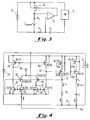
- FIG. 2 is a more detailed circuit diagram of the pacemaker of this invention with the improved EOL detector.
- Figure 3 is a simplified circuit diagram showing the feedback configuration for obtaining an input signal representative of pacemaker current.
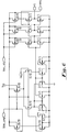
- Figure 4 is a more detailed circuit diagram of the input stage for providing a signal representative of pacemaker current.
- FIG. 5A is a simplified block diagram showing the pacemaker system of this invention, comprising the implanted pacemaker and external apparatus which has the capacity to communicate with the implanted pacemaker.
- Figure 5B shows a simplified flow diagram for calculating projected EOL of the implanted pacemaker.
- FIG. 6 is a circuit of a Schmitt Trigger suitable for use in the implantable pacemaker embodiment of this invention.
- EOL detector or simply detector, may comprise either a circuit for obtaining a measure of battery energy expenditure, or apparatus which both obtains a measure of battery energy expenditure and provides an indication of remaining lifetime.
- pacemaker circuitry 21 comprises all circuitry, both hardware and software, within the implanted pacemaker, except for the EOL detector circuitry.
- pacemaker circuitry 21 comprises one or more generators for generating stimulus pulses, hardware and/or software for performing logic functions and making decisions as to when and when not to deliver stimulus pulses, and all other functions that are well known in the pacemaker art.
- Pacemaker circuitry block 21 may also embrace leads for delivering stimulus pulses to a patient's heart and for receiving therefrom signals representative of natural heartbeats.
- the current through pacemaker circuitry 21 is designated as I l .
- the pacemaker also comprises a battery 22, which provides power to the pacemaker.
- the detector circuit indicated at 23 comprises an input circuit 25 designed to output a current proportional to I l , namely a current indicated as KI l .
- a sense resistor R1 develops thereacross a voltage proportional to I l .
- a second resistor, indicated as R2 is connected at one end to a node between battery 22 and resistor R1 and at its other end to an input to circuit 25. The other end of resistor R1 is also connected as a second input to circuit 25.
- the sense current (I s ) through resistor R2 equals approximately R1/R2 x I l .
- Circuit 25 provides an output current proportional to the input current, such that I out flows into and charges capacitor C.
- Block 26 is a circuit which repeatedly discharges capacitor C and, upon each such discharge, obtains a measure of the pacemaker circuit current times the time that the current has flown, i.e., I l x t pm , which in turn is a measure of the energy discharge from the battery during the time of charging the capacitor.
- I l x t pm a measure of the pacemaker circuit current times the time that the current has flown
- Each such measure corresponding to each such capacitor discharge is added, or accumulated, to obtain an overall measure of I l x t pm , representing overall battery discharge.
- the overall measure can be accessed through an external interrogating device, in a well known manner.
- Resistor R1 across which I l flows, is selected as approximately 1K.
- R1 is a compromise between obtaining accuracy, minimizing power dissipation, and reducing the voltage drop across R1.
- the choice of about 1K ohms is made to optimize these factors.
- the value of R2 is chosen as approximately 106, or 1 Meg.
- the input current I s shown at node 27 connected to input circuit 25, is proportional to I l by a factor K, where K is the ratio of R1 to R2.
- circuit 25 comprises an operational amplifier
- I s R1/R2 x I l .
- the input stage is further designed to provide an output charging current for the capacitor C of the same value, i.e., R1/R2 x I l .
- V a a positive Schmitt trigger threshold voltage
- V th+ the output from the Schmitt trigger 28 closes analog gate 29.
- a fixed discharge current I d provided by a bias block 61, discharges capacitor C until V a reaches V th- (a negative Schmitt trigger threshold voltage).
- gate 29 is switched off and the voltage V a begins to increase again. This procedure of discharging the capacitor to V th- and then starting a new cycle of charging, is referred to as zeroing out the accumulated voltage signal.
- I d the time that it takes to discharge capacitor C with the programmed current value I d , enables a determination of the accumulated charge on capacitor C, which in turn represents a measure of the energy expended by the battery 22.
- I d may be in the range of about 200nA to 1000nA.
- I l x t pm k x t d , where k depends upon the values of R2, R1 and I d .
- AND gate 31 is connected to receive a first input from the Schmitt trigger 28 and a second input from a 1 KHz generator 54. During discharge, the Schmitt trigger output enables clock pulses to pass through the AND gate, which pulses are then counted in counter 60. The number of pulses delivered to the counter while the capacitor is discharging is a measure of t d , and therefore of I l x t pm .
- the measure of current consumption provided by this circuit is effectively independent of the value of the capacitor C. If the capacitance varies, this results in a change in the accumulated charge before V th+ is reached. But, by discharging the capacitor with the fixed current I d , the count of the 1 KHz pulses is always proportional to the charge withdrawn from the capacitor, and thus to current consumption. As long as the capacitor has a value such that the time of discharge (t d ) is large compared to the 1 ms period between the 1 KHz pulses, the accuracy is effectively independent of variations in the value of C.
- the pulse rate of 1 KHz is a compromise between current consumption and accuracy. Other rates can be used, e.g., between about 500 Hz and 5000 Hz.
- the counting mechanism is a measure of the capacitor discharge time. If it is assumed that the Schmitt trigger has a threshold hysteresis, or voltage window of 1 V, and the discharge current is 1000nA, then: In order to achieve an accuracy of 0.5% or greater in view of the count mechanism induced error, the minimum discharge period is 100 ms. This would yield a capacitance value of 100nF. For a shorter discharge window, e.g., .75 v, a proportionately greater capacitance value is used. To be safely within the 0.5% error tolerance, a capacitance value in the range of 100-200nF is appropriate.
- the bias block provides an analog bias current to input stage 28; an analog bias voltage to Schmitt trigger 28; a digital bias voltage to Schmitt trigger 28; a discharge current to gate 29; and a digital bias current to AND gate 31.
- the bias block starts with a 20 nA reference 53 from pacemaker circuitry 21 and builds separate current sources therefrom.
- a modified cascode current mirror is suitable for providing I d .
- FIG 3 a simplified diagram showing the feedback arrangement is provided.
- the input stage 25 is the most critical stage of the EOL detection subsystem.
- the main task of the input stage is to deliver a charging current for the capacitor C which is proportional to the line current I l . While the minimal line current for a typical pacemaker is about 5 ⁇ A, suggesting a high value of resistance R1, the value of R1 is limited by the fact that at large line currents the voltage over the pacemaker circuitry drops with the value of the voltage across R1. This forces the compromise discussed above.
- the input signal is developed at node 27, as also seen in Figure 2.
- This signal is inputted into an operational amplifier comprising transistors 34-41, having an output at the node indicated at 67.
- the feedback for the operational amplifier (corresponding to single transistor 32 shown in Figure 3) is provided by the combination of transistors 43A and 43B.
- the output current, designated I out is set equal to the input current (I s ) by a current mirror circuit which includes transistors 44A and 44B, which are driven in a current mirror configuration with transistors 43A and 43B.
- the circuit provides a current proportional to I l into capacitor C.
- a bias port from bias block 61 is used to input the bias stage with a predetermined current.
- FIG 4 shows, for each of the transistors, the W/L ratio.
- the W/L ratios can affect the phase, gain, etc. and are important in the pacemaker embodiment for minimizing current drain.
- the design shown is illustrative, and not critical, and variations are well within the skill of a routine design engineer for providing a circuit with low current drain.
- Transistor 37 is indicated as 2*100/20, and transistor 34 is indicated as 2*120/20, each representing two transistors in parallel. The respective transistors 34, 37 are unbalanced in order to provide a built-in offset.
- pacemaker 20 may incorporate both hardware 45 and software 46, in a known fashion.
- the hardware has circuitry for delivering stimulus pulses and receiving signals representative of natural heartbeats and other information from the heart.
- the software may be stored in the memory section of a processor chip, and may include additional RAM and ROM.
- the hardware 45 also interacts with an external programmer 50, in a known fashion.
- Programmer 50 interfaces with an input/output device (I/O) 51, such as a keyboard and/or display, and may also interface with a printer 52.
- I/O input/output device
- Programmer 50 may be used to program the pacemaker, and also may be used in this system for enabling a physician to make precise determinations of EOL. Programmer 50 may suitably carry out the processing steps shown in Figure 5B. As there illustrated, at step 55, the programmer interrogates the pacemaker and obtains current pacemaker operating parameters, i.e., voltage and duration of the pulse, pacing rate, etc. At step 57, the programmer reads out from pacemaker storage a measure of the energy consumption, as stored at counter 60 in the pacemaker. At step 59, the programmer calculates projected EOL.
- current pacemaker operating parameters i.e., voltage and duration of the pulse, pacing rate, etc.
- the programmer reads out from pacemaker storage a measure of the energy consumption, as stored at counter 60 in the pacemaker.
- the programmer calculates projected EOL.
- This includes determining battery capacity which is pre-stored in memory, subtracting the energy consumption, and projecting the amount of time the pacemaker would operate at the present operating parameters to consume the remaining battery energy to the point of EOL. It is to be noted that, alternately, these operations may in fact be carried out in the implanted pacemaker, either automatically or on command from an external programmer, following which the projected EOL is read out by the physician, or some automatic indication is given to the patient.
- the circuit should be very low power drain, and have good accuracy and a high slew-rate.
- the embodiment of Figure 6 is representative of a preferred Schmitt Trigger. Variations of the overall circuit arrangement, for achieving substantially the same EOL result in substantially the same way, are within the scope of the invention.
- the invention can be used in any device where battery depletion and EOL are important, and some automatic means of determining and indicating EOL is desirable.
- the invention is useful for other implantable medical devices, and for any battery-driven device where accuracy of detecting EOL is important.
Abstract
Description
- The present invention relates to cardiac pacemakers and, more particularly, to cardiac pacemakers with the facility to continuously detect a measure of battery expenditure so as to predict nominal pacemaker end-of-life (EOL).
- In the area of implantable cardiac pacemakers, it has long been recognized that it is important to have the capacity to determine a measure of the effective remaining lifetime of the implanted pacemaker. Although great improvements have been made in the batteries that are used in pacemakers, extending significantly the available lifetime of pacemakers, there remains a need to have accurate information from which to predict EOL. As used herein, and as is common in the pacemaker art, end-of-life refers to a time when the battery has been drained sufficiently that the pacemaker should be replaced. Thus, EOL generally does not refer to a time when a pacemaker actually ceases to operate effectively, but a time by which the pacemaker should be replaced while there is still a sufficient factor of safety. Thus, e.g., the pacemaker manufacturer may recommend a replacement of the pacemaker at a time when it actually has an estimated three months of lifetime remaining, to guarantee that replacement takes place before there is a significant danger of actual cessation of pacemaker operation.
- An early technique for EOL detection in pacemakers was founded upon the characteristics of the battery impedance. Based upon the observation that battery internal impedance was substantially constant throughout most of the battery lifetime, and then began to increase as battery exhaustion approached, the standard technique utilized was to isolate the battery from the pacemaker briefly in order to get an internal impedance measurement. See, for example, U.S. Patent 5,317,020, assigned to Medtronic, Inc. However, in the latest generation of batteries utilized in implantable pacemakers, the impedance change occurs too quickly to provide sufficient warning, and cannot be reliably detected safely in advance of effective battery exhaustion. Consequently, another engineering approach to the matter is required.
- The more recent solution to the problem of measuring EOL in the pacemaker art is based on the fact that the battery energy at start-of-life is accurately known. The pacemaker is provided with a circuit for obtaining a measure of total, or integrated battery current expenditure, and determining from this measure what percentage of battery energy has been depleted. By making it possible for a physician to determine what percentage of the battery capacity has been expended, the physician can project a remaining safe lifetime. The basic concept of detecting EOL by accumulating a measure of energy usage in an implanted pacemaker is illustrated in U.S. Patents 4,556,061 and 4,715,381. In Patent No. 4,556,061, there is provided a battery consumption monitor circuit which develops with an internal counter a cumulative count representative of energy consumption by the pacemaker. A sense resistor is used to develop a voltage representative of pacemaker current flow, which voltage is imposed upon a voltage-controlled oscillator (VCO), the output of which is inputted into the internal counter. The counter continuously accumulates the pulses so as to provide a measure of the integral of battery current flow, and thus total energy expenditure. However, the accuracy of the VCO is a function of its capacitor, such that the use of VCO in this manner makes the EOL detector capacitor-dependent. It is very difficult and expensive to provide an extremely precise capacitor value for an implantable pacemaker application. Further, the expected variability of the capacitor value over the lifetime of an implanted pacemaker, which may be up to ten or more years, leads to a loss of accuracy. Accordingly, what is needed is a more reliable form of detecting battery consumption and, in particular, an EOL detector which is not capacitor-dependent. Optimally, what is desired is an EOL circuit where, to the extent any capacitor is utilized, the capacitor can change in value over the life of the pacer and not affect the accuracy of the measurement, i.e., the EOL detector is capacitor-independent and otherwise highly reliable.
- U.S. Patent No. 4,715,381 illustrates a technique of making calculations of approximate battery energy expenditure, rather than actually measuring battery consumption. This reference shows a stimulation pulse counter which counts the number of delivered stimulus pulses. This information is utilized together with the programming parameters to determine the total amount of energy of the delivered pulses over an elapsed time. This calculated signal is added to a fundamental consumption signal which is based upon certain approximations and assumptions, and used to derive a signal representative of approximate total battery expenditure. This technique clearly provides at best an approximation, and is inherently subject to a greater probability of inaccuracy than the energy consumption technique. Further, neither of the prior art techniques are as energy efficient as desired, i.e., the EOL detector itself involves counters, oscillators and the like which are constantly operating and consume an undesirable amount of energy. Thus, there remains a substantial need in the pacemaker art for an improved EOL detector which is more reliable and accurate, can be built with minimum cost, and which itself draws an optimally minimum amount of energy from the pacemaker battery.
- In accordance with the above-described need in the art, there is provided an implantable pacemaker system with an improved EOL detector with a reliable circuit for measuring pacemaker consumption, and means for projecting EOL in the implanted pacemaker. The detector provides an effectively capacitor-independent circuit for providing an accurate measure of total energy expenditure from the battery. The system further provides for an automatic calculation of remaining battery life and thus of anticipated EOL. The EOL detector comprises a circuit for accumulating a signal representative of recent energy consumption, which signal is obtained by accumulating on a capacitor a signal representative of the integral of pacemaker current with time since the initiation of the last accumulation on the capacitor. This signal is read when the capacitor voltage reaches a trigger threshold, the signal reading being accomplished by generating pulses representative of the accumulated charge being discharged from the capacitor. An accurate reading is made by discharging the capacitor at a fixed discharge current over the time of current discharge, and generating a number of pulses proportional to the time of discharge. The pulses, which represent energy consumed by the pacemaker while the capacitor was charging, are accumulated in a counter. Following discharge or zeroing out of the capacitor, the accumulation of the running measure of battery expenditure is repeated, following which another readout takes place. The EOL detector thus cycles through the steps of reading out a measure of energy consumption since the last reading, accumulating the measure of energy consumption, and repeating these steps. The technique of timing a constant current discharge from the capacitor provides a measure which is substantially independent of capacitor variation, thereby providing an improved EOL detector with greater accuracy and reliability.
- Figure 1 is a block diagram showing the basic circuit components of an implantable pacemaker with a preferred embodiment of the improved EOL detector of this invention.
- Figure 2 is a more detailed circuit diagram of the pacemaker of this invention with the improved EOL detector.
- Figure 3 is a simplified circuit diagram showing the feedback configuration for obtaining an input signal representative of pacemaker current.
- Figure 4 is a more detailed circuit diagram of the input stage for providing a signal representative of pacemaker current.
- Figure 5A is a simplified block diagram showing the pacemaker system of this invention, comprising the implanted pacemaker and external apparatus which has the capacity to communicate with the implanted pacemaker.
- Figure 5B shows a simplified flow diagram for calculating projected EOL of the implanted pacemaker.
- Figure 6 is a circuit of a Schmitt Trigger suitable for use in the implantable pacemaker embodiment of this invention.
- Referring now to the figures, the preferred embodiment of this invention is described. As used in the claims appended hereto, the term EOL detector, or simply detector, may comprise either a circuit for obtaining a measure of battery energy expenditure, or apparatus which both obtains a measure of battery energy expenditure and provides an indication of remaining lifetime.
- Referring now to Figure 1, there is shown a simplified block diagram representing the basic components of a
pacemaker 20 having an improved EOL detector. The pacemaker haspacemaker circuitry 21, which comprises all circuitry, both hardware and software, within the implanted pacemaker, except for the EOL detector circuitry. Thus,pacemaker circuitry 21 comprises one or more generators for generating stimulus pulses, hardware and/or software for performing logic functions and making decisions as to when and when not to deliver stimulus pulses, and all other functions that are well known in the pacemaker art.Pacemaker circuitry block 21 may also embrace leads for delivering stimulus pulses to a patient's heart and for receiving therefrom signals representative of natural heartbeats. The current throughpacemaker circuitry 21 is designated as Iℓ. The pacemaker also comprises abattery 22, which provides power to the pacemaker. - The detector circuit indicated at 23 comprises an
input circuit 25 designed to output a current proportional to Iℓ, namely a current indicated as KIℓ. A sense resistor R₁ develops thereacross a voltage proportional to Iℓ. A second resistor, indicated as R₂ is connected at one end to a node betweenbattery 22 and resistor R₁ and at its other end to an input tocircuit 25. The other end of resistor R₁ is also connected as a second input tocircuit 25. As is explained further in connection with Figure 3, the sense current (Is) through resistor R₂ equals approximately
Circuit 25 provides an output current proportional to the input current, such that Iout flows into and chargescapacitor C. Block 26 is a circuit which repeatedly discharges capacitor C and, upon each such discharge, obtains a measure of the pacemaker circuit current times the time that the current has flown, i.e., Iℓ x tpm, which in turn is a measure of the energy discharge from the battery during the time of charging the capacitor. Each such measure corresponding to each such capacitor discharge is added, or accumulated, to obtain an overall measure of Iℓ x tpm, representing overall battery discharge. The overall measure can be accessed through an external interrogating device, in a well known manner. - Referring now to Figure 2, there is shown a more detailed circuit diagram of the pacemaker of this invention with an improved EOL detector. Resistor R₁, across which Iℓ flows, is selected as approximately 1K. As is appreciated by those knowledgeable in the circuit arts, the choice of R₁ is a compromise between obtaining accuracy, minimizing power dissipation, and reducing the voltage drop across R₁. The choice of about 1K ohms is made to optimize these factors. The value of R₂ is chosen as approximately 10⁶, or 1 Meg. The input current Is, shown at
node 27 connected to inputcircuit 25, is proportional to Iℓ by a factor K, where K is the ratio of R₁ to R₂. As seen also in Figure 3, wherecircuit 25 comprises an operational amplifier,

Schmitt trigger 28 closesanalog gate 29. A fixed discharge current Id, provided by abias block 61, discharges capacitor C until Va reaches Vth- (a negative Schmitt trigger threshold voltage). At this moment,gate 29 is switched off and the voltage Va begins to increase again. This procedure of discharging the capacitor to Vth-and then starting a new cycle of charging, is referred to as zeroing out the accumulated voltage signal. - It is seen that the time that it takes to discharge capacitor C with the programmed current value Id, enables a determination of the accumulated charge on capacitor C, which in turn represents a measure of the energy expended by the
battery 22. The energy, or amp hours (Ah) is obtained from the following expressions:

where tpm is the time during which the pacemaker has been operating,
Iℓ is the instantaneous line current value (µA), td is the period during which the capacitor is discharged, and
Id is the capacitor C discharging current set by thebias block 61. For example, Id may be in the range of about 200nA to 1000nA.
Consequently:

where k depends upon the values of R₂, R₁ and Id. ANDgate 31 is connected to receive a first input from theSchmitt trigger 28 and a second input from a 1KHz generator 54. During discharge, the Schmitt trigger output enables clock pulses to pass through the AND gate, which pulses are then counted incounter 60. The number of pulses delivered to the counter while the capacitor is discharging is a measure of td, and therefore of Iℓ x tpm. - As seen from the last equation above, the measure of current consumption provided by this circuit is effectively independent of the value of the capacitor C. If the capacitance varies, this results in a change in the accumulated charge before Vth+ is reached. But, by discharging the capacitor with the fixed current Id, the count of the 1 KHz pulses is always proportional to the charge withdrawn from the capacitor, and thus to current consumption. As long as the capacitor has a value such that the time of discharge (td) is large compared to the 1 ms period between the 1 KHz pulses, the accuracy is effectively independent of variations in the value of C. The pulse rate of 1 KHz is a compromise between current consumption and accuracy. Other rates can be used, e.g., between about 500 Hz and 5000 Hz.
- It is to be noted that the mechanism of counting the discharge time by counting pulses does introduce some error. For a 1 KHz signal, the quanta or period of 1 ms. There is a theoretical start counting error induced by the time offset between the rising edge of the 1 KHz signal and the rising signal of the Schmitt trigger output signal. Likewise, there is a stop counting error due to the time offset between the falling edge of the 1 KHz signal and the falling edge of the Schmitt trigger output signal. While a higher pulse rate would lead to less error and greater accuracy, such a higher rate would require a counter with greater capacity to count the increased number of pulses. Since a high capacity counter is not desirable for an implantable device, in the preferred embodiment a 1 KHz signal is used and the value of the capacitor C is selected so that accuracy is maintained within a predetermined tolerance.
- The counting mechanism is a measure of the capacitor discharge time. If it is assumed that the Schmitt trigger has a threshold hysteresis, or voltage window of 1 V, and the discharge current is 1000nA, then:

In order to achieve an accuracy of 0.5% or greater in view of the count mechanism induced error, the minimum discharge period is 100 ms. This would yield a capacitance value of 100nF. For a shorter discharge window, e.g., .75 v, a proportionately greater capacitance value is used. To be safely within the 0.5% error tolerance, a capacitance value in the range of 100-200nF is appropriate. - It is to be noted that a simpler embodiment of the invention can be obtained at some sacrifice of accuracy. In such a case, the 1
KHz generator 54 and the ANDgate 31 are eliminated, and only the signal changes from the output ofcircuit 28 are counted. This gives a good result, but not as good as the preferred embodiment, since changes in C or Vth+ and Vth- affect accuracy. - In practice, the bias block provides an analog bias current to input
stage 28; an analog bias voltage toSchmitt trigger 28; a digital bias voltage toSchmitt trigger 28; a discharge current togate 29; and a digital bias current to ANDgate 31. The bias block starts with a 20nA reference 53 frompacemaker circuitry 21 and builds separate current sources therefrom. A modified cascode current mirror is suitable for providing Id. - Referring now to Figures 3 and 4, the input circuit will be described. In Figure 3, a simplified diagram showing the feedback arrangement is provided. The
input stage 25 is the most critical stage of the EOL detection subsystem. The main task of the input stage is to deliver a charging current for the capacitor C which is proportional to the line current Iℓ. While the minimal line current for a typical pacemaker is about 5 µA, suggesting a high value of resistance R₁, the value of R₁ is limited by the fact that at large line currents the voltage over the pacemaker circuitry drops with the value of the voltage across R₁. This forces the compromise discussed above. The feedback configuration of Figure 3 includes a transistor 32 (pmos) in its feedback loop, to provide the relationship
node 27, as also seen in Figure 2. This signal is inputted into an operational amplifier comprising transistors 34-41, having an output at the node indicated at 67. The feedback for the operational amplifier (corresponding tosingle transistor 32 shown in Figure 3) is provided by the combination oftransistors 43A and 43B. The output current, designated Iout is set equal to the input current (Is) by a current mirror circuit which includestransistors 44A and 44B, which are driven in a current mirror configuration withtransistors 43A and 43B. Thus, the circuit provides a current proportional to Iℓ into capacitor C. A bias port frombias block 61 is used to input the bias stage with a predetermined current. - Figure 4 shows, for each of the transistors, the W/L ratio. The W/L ratios can affect the phase, gain, etc. and are important in the pacemaker embodiment for minimizing current drain. The design shown is illustrative, and not critical, and variations are well within the skill of a routine design engineer for providing a circuit with low current drain.
Transistor 37 is indicated as 2*100/20, andtransistor 34 is indicated as 2*120/20, each representing two transistors in parallel. Therespective transistors - Referring now to Figures 5A and 5B, there are shown further features of the overall pacemaker of this invention, having a subsystem for indicating EOL. As indicated in Fig. 5A,
pacemaker 20 may incorporate bothhardware 45 andsoftware 46, in a known fashion. The hardware has circuitry for delivering stimulus pulses and receiving signals representative of natural heartbeats and other information from the heart. The software may be stored in the memory section of a processor chip, and may include additional RAM and ROM. Thehardware 45 also interacts with anexternal programmer 50, in a known fashion.Programmer 50 interfaces with an input/output device (I/O) 51, such as a keyboard and/or display, and may also interface with aprinter 52.Programmer 50 may be used to program the pacemaker, and also may be used in this system for enabling a physician to make precise determinations of EOL.Programmer 50 may suitably carry out the processing steps shown in Figure 5B. As there illustrated, atstep 55, the programmer interrogates the pacemaker and obtains current pacemaker operating parameters, i.e., voltage and duration of the pulse, pacing rate, etc. Atstep 57, the programmer reads out from pacemaker storage a measure of the energy consumption, as stored at counter 60 in the pacemaker. Atstep 59, the programmer calculates projected EOL. This includes determining battery capacity which is pre-stored in memory, subtracting the energy consumption, and projecting the amount of time the pacemaker would operate at the present operating parameters to consume the remaining battery energy to the point of EOL. It is to be noted that, alternately, these operations may in fact be carried out in the implanted pacemaker, either automatically or on command from an external programmer, following which the projected EOL is read out by the physician, or some automatic indication is given to the patient. - There has thus been disclosed an efficient and accurate subsystem for determining a measure of EOL in an implanted pacemaker. The configuration of the circuit results in a determination which is effectively independent of the capacitor which is used, thereby significantly enhancing accuracy of the EOL determination. While a specific circuit for the input stage has been illustrated, the other circuits are a matter of design choice, it being understood that for a pacemaker embodiment a low current drain is desirable. Thus, the
Schmitt trigger 28, the ANDcircuit 31, thecounter 60 and thebias block 61 may be conventional circuits which are well known in the art. Indeed, accuracy does not depend on the threshold of the Schmitt trigger. Of course, a relatively sophisticated design may be desired for a pacemaker, where long-term reliability and low energy consumption are desired. For an implantable pacemaker, the circuit should be very low power drain, and have good accuracy and a high slew-rate. The embodiment of Figure 6 is representative of a preferred Schmitt Trigger. Variations of the overall circuit arrangement, for achieving substantially the same EOL result in substantially the same way, are within the scope of the invention. - While the preferred embodiment of the invention has been described as an implantable pacemaker, it is evident that the invention can be used in any device where battery depletion and EOL are important, and some automatic means of determining and indicating EOL is desirable. Thus, the invention is useful for other implantable medical devices, and for any battery-driven device where accuracy of detecting EOL is important.
Claims (10)
- A pacemaker having a battery, pacemaker circuitry for carrying out pacing functions, and an energy consumption, said detector comprising accumulating means for accumulating a signal representative of the integral of pacemaker circuitry current over the time since it last started to accumulate said signals, further characterized by(a) readout means for reading out said accumulated signal when it reaches a predetermined threshold and for developing therefrom a measure of battery expenditure over said time;(b) said readout means having means for zeroing out said accumulated signal so that said accumulating means repeats the function of accumulating a said representative signal from the time of said zeroing out until the time of the next readout; and(c) means for accumulating signals which have been read out and for storing a signal representative of overall battery expenditure.
- The pacemaker as described in claim 1, wherein said accumulating means comprises sense means for continuously sensing a measure of current flow through said pacemaker circuitry.
- The pacemaker as described in claim 1, wherein said accumulating means comprises a capacitor and charging means for charging said capacitor with a current proportional to said pacemaker circuitry current.
- The pacemaker as described in claim 1, wherein said accumulating means comprises a current sense means for sensing the pacemaker circuitry current, in combination with a circuit for providing a current having a predetermined linear relation to said sensed current.
- The pacemaker as described in claim 3, wherein said readout means comprises means for discharging said capacitor to a predetermined value and for developing a series of pulses during the time of discharge of said capacitor, said series of pulses representing a measure of the energy discharged from said capacitor.
- The pacemaker as described in claim 5, wherein said readout means comprises means for initiating readout of said capacitor when the voltage on said capacitor reaches a first threshold, and means for terminating readout of said capacitor when the voltage on said capacitor reaches a second threshold.
- The pacemaker as described in claim 3, wherein said readout means comprises discharge means for discharging said capacitor at a constant discharge current.
- The pacemaker as described in claim 1, in combination with means for inputting pacemaker operating parameter data, means for obtaining from said operating data an estimate of the rate at which said pacemaker is currently using energy from said battery, and means for determining a measure of EOL from said estimate of using energy and from said stored signal representative of overall battery expenditure.
- An implantable pacemaker system having a battery for the supply of energy, a pacing subsystem powered by said battery for generating and delivering pacing pulses to a patient, and a circuit for obtaining a measure of the energy discharge of said battery, said circuit comprising:a) a sense circuit for sensing current through said pacemaker circuitry, having a capacitor and a charging circuit for charging said capacitor with a charge which is a measure of the integral of said sensed current over time, and thus of battery energy discharge while said capacitor was charging;b) discharge means for discharging said capacitor at a fixed discharge current, whereby the time of discharge is a measure of said integral and independent of the value of said capacitor; andc) a measuring circuit for developing a representative signal representative of said discharge time and thus representative of said integral.
- The pacemaker system as described in claim 9, further comprising cycle means to continuously enable said charging and said discharging, and means to accumulate said representative signals, thereby providing a measure of overall battery discharge.
Applications Claiming Priority (2)
| Application Number | Priority Date | Filing Date | Title |
|---|---|---|---|
| US132713 | 1993-10-06 | ||
| US08/132,713 US5458624A (en) | 1993-10-06 | 1993-10-06 | Cardiac pacing system with improved end-of-life detector |
Publications (2)
| Publication Number | Publication Date |
|---|---|
| EP0647455A1 true EP0647455A1 (en) | 1995-04-12 |
| EP0647455B1 EP0647455B1 (en) | 2001-07-25 |
Family
ID=22455268
Family Applications (1)
| Application Number | Title | Priority Date | Filing Date |
|---|---|---|---|
| EP94115673A Expired - Lifetime EP0647455B1 (en) | 1993-10-06 | 1994-10-05 | Cardiac pacing system with improved end-of-life detector |
Country Status (3)
| Country | Link |
|---|---|
| US (1) | US5458624A (en) |
| EP (1) | EP0647455B1 (en) |
| DE (1) | DE69427798T2 (en) |
Families Citing this family (45)
| Publication number | Priority date | Publication date | Assignee | Title |
|---|---|---|---|---|
| US5591211A (en) * | 1994-12-09 | 1997-01-07 | Ventritex, Inc. | Defibrillator having redundant switchable high voltage capacitors |
| US5620474A (en) * | 1995-04-24 | 1997-04-15 | Vitatron Medical, B.V. | System and method for determining indicated pacemaker replacement time based upon battery impedance measurement |
| US6108579A (en) * | 1996-04-15 | 2000-08-22 | Pacesetter, Inc. | Battery monitoring apparatus and method for programmers of cardiac stimulating devices |
| US5769873A (en) * | 1996-10-15 | 1998-06-23 | Pacesetter, Inc. | Meter for measuring battery charge delivered in an implantable device |
| US5741307A (en) * | 1997-01-21 | 1998-04-21 | Pacesetter, Inc. | Method for determining an ICD replacement time |
| US6167309A (en) * | 1997-09-15 | 2000-12-26 | Cardiac Pacemakers, Inc. | Method for monitoring end of life for battery |
| US6631293B2 (en) * | 1997-09-15 | 2003-10-07 | Cardiac Pacemakers, Inc. | Method for monitoring end of life for battery |
| US6820019B1 (en) * | 1999-07-31 | 2004-11-16 | Medtronic, Inc. | Device and method for determining and communicating the remaining life of a battery in an implantable neurological tissue stimulating device |
| US6400988B1 (en) | 2000-02-18 | 2002-06-04 | Pacesetter, Inc. | Implantable cardiac device having precision RRT indication |
| US6490484B2 (en) | 2001-01-24 | 2002-12-03 | Cardiac Pacemakers, Inc. | Apparatus and method for estimating battery condition in implantable cardioverter/defibrillators |
| US7001359B2 (en) * | 2001-03-16 | 2006-02-21 | Medtronic, Inc. | Implantable therapeutic substance infusion device with active longevity projection |
| US6584355B2 (en) * | 2001-04-10 | 2003-06-24 | Cardiac Pacemakers, Inc. | System and method for measuring battery current |
| US7142923B2 (en) * | 2003-02-21 | 2006-11-28 | Medtronic, Inc. | Implantable neurostimulator programming with battery longevity indication |
| US6901293B2 (en) | 2003-04-07 | 2005-05-31 | Medtronic, Inc. | System and method for monitoring power source longevity of an implantable medical device |
| US7239146B2 (en) * | 2003-07-11 | 2007-07-03 | Cardiac Pacemakers, Inc. | Indicator of remaining energy in storage cell of implantable medical device |
| US7215999B1 (en) | 2003-08-06 | 2007-05-08 | Pacesetter, Inc. | Battery charge indicator for implantable pacemakers and defibrillators |
| US6940255B2 (en) * | 2003-10-23 | 2005-09-06 | Cardiac Pacemakers, Inc. | Battery charge indicator such as for an implantable medical device |
| US7194308B2 (en) | 2003-11-12 | 2007-03-20 | Cardiac Pacemakers, Inc. | System and method for monitoring or reporting battery status of implantable medical device |
| US8086318B2 (en) * | 2004-02-12 | 2011-12-27 | Ndi Medical, Llc | Portable assemblies, systems, and methods for providing functional or therapeutic neurostimulation |
| US20050277994A1 (en) * | 2004-06-09 | 2005-12-15 | Mcnamee Paul | Apparatus and method for estimating battery condition in implantable cardiac devices |
| US7221977B1 (en) | 2004-06-25 | 2007-05-22 | Pacesetter, Inc. | Method and apparatus for measuring battery depletion in implantable medical devices |
| US20060025828A1 (en) * | 2004-07-28 | 2006-02-02 | Armstrong Randolph K | Impedance measurement for an implantable device |
| US7769455B2 (en) * | 2006-01-27 | 2010-08-03 | Cyberonics, Inc. | Power supply monitoring for an implantable device |
| FR2903211B1 (en) * | 2006-06-30 | 2009-03-06 | Gen Electric | METHODS AND DEVICES FOR CORRECTING IMPLANT MAMMOGRAPHY AND SEGMENTING AN IMPLANT |
| US20080040056A1 (en) * | 2006-08-11 | 2008-02-14 | Ventrassist Pty Ltd. & The University Of New South Wales | Battery recharging and replacement system |
| US8055343B2 (en) * | 2006-10-20 | 2011-11-08 | Cardiac Pacemakers, Inc. | Dynamic battery management in an implantable device |
| US20080177345A1 (en) * | 2007-01-18 | 2008-07-24 | Schmidt Craig L | Methods for estimating remaining battery service life in an implantable medical device |
| US8150521B2 (en) * | 2007-03-15 | 2012-04-03 | Cvrx, Inc. | Methods and devices for controlling battery life in an implantable pulse generator |
| WO2009015081A2 (en) * | 2007-07-20 | 2009-01-29 | Cvrx, Inc. | Elective service indicator based on pulse count for implantable device |
| EP2219730B1 (en) * | 2007-12-13 | 2015-01-21 | Cardiac Pacemakers, Inc. | Battery depletion detection in an implantable device |
| US8090566B2 (en) * | 2008-04-03 | 2012-01-03 | Medtronic, Inc. | Battery longevity monitoring |
| US8823382B2 (en) * | 2008-04-30 | 2014-09-02 | Medtronic, Inc. | System and method for monitoring a power source of an implantable medical device |
| US8868187B2 (en) * | 2008-06-17 | 2014-10-21 | Cardiac Pacemakers, Inc. | Battery depth of discharge in an implantable device |
| US8874229B2 (en) | 2010-04-28 | 2014-10-28 | Cyberonics, Inc. | Delivering scheduled and unscheduled therapy without detriment to battery life or accuracy of longevity predictions |
| US8452395B2 (en) * | 2010-07-06 | 2013-05-28 | Medtronic, Inc. | Battery longevity estimator that accounts for episodes of high current drain |
| US8401646B2 (en) * | 2010-10-21 | 2013-03-19 | Medtronic, Inc. | Method and apparatus to determine the relative energy expenditure for a plurality of pacing vectors |
| US8577459B2 (en) | 2011-01-28 | 2013-11-05 | Cyberonics, Inc. | System and method for estimating battery capacity |
| US8761884B2 (en) | 2011-04-14 | 2014-06-24 | Cyberonics, Inc. | Device longevity prediction for a device having variable energy consumption |
| US8761885B2 (en) | 2011-04-29 | 2014-06-24 | Cyberonics, Inc. | Battery life estimation based on voltage depletion rate |
| US9199087B2 (en) | 2011-11-21 | 2015-12-01 | Medtronic, Inc. | Apparatus and method for selecting a preferred pacing vector in a cardiac resynchronization device |
| US10413719B2 (en) * | 2016-04-15 | 2019-09-17 | Innovative Health Solutions, Inc. | Methods of treating disease using auricular peripheral nerve field stimulation |
| US9616238B2 (en) | 2013-12-05 | 2017-04-11 | Medtronic, Inc. | Method and apparatus for determining longevity |
| US9656088B2 (en) | 2014-11-26 | 2017-05-23 | Medtronic, Inc. | Method and apparatus for determining longevity |
| US10639481B2 (en) | 2018-01-08 | 2020-05-05 | Medtronic, Inc. | Power source longevity |
| US11776684B2 (en) * | 2019-09-26 | 2023-10-03 | Pacesetter, Inc | Method and device for managing energy usage by a medical device |
Citations (3)
| Publication number | Priority date | Publication date | Assignee | Title |
|---|---|---|---|---|
| US4556061A (en) * | 1982-08-18 | 1985-12-03 | Cordis Corporation | Cardiac pacer with battery consumption monitor circuit |
| US4715381A (en) * | 1985-10-02 | 1987-12-29 | Siemens Aktiengesellschaft | Battery test circuit for a heart pacemaker |
| US5137021A (en) * | 1990-11-29 | 1992-08-11 | Medtronic, Inc. | Lead current measurement circuit |
Family Cites Families (2)
| Publication number | Priority date | Publication date | Assignee | Title |
|---|---|---|---|---|
| DE2913399A1 (en) * | 1979-03-31 | 1980-10-09 | Biotronik Mess & Therapieg | CIRCUIT FOR CHECKING THE BATTERY STATUS OF A PACEMAKER |
| US5137020A (en) * | 1990-11-29 | 1992-08-11 | Medtronic, Inc. | Battery impedance measurement apparatus |
-
1993
- 1993-10-06 US US08/132,713 patent/US5458624A/en not_active Expired - Lifetime
-
1994
- 1994-10-05 DE DE69427798T patent/DE69427798T2/en not_active Expired - Lifetime
- 1994-10-05 EP EP94115673A patent/EP0647455B1/en not_active Expired - Lifetime
Patent Citations (3)
| Publication number | Priority date | Publication date | Assignee | Title |
|---|---|---|---|---|
| US4556061A (en) * | 1982-08-18 | 1985-12-03 | Cordis Corporation | Cardiac pacer with battery consumption monitor circuit |
| US4715381A (en) * | 1985-10-02 | 1987-12-29 | Siemens Aktiengesellschaft | Battery test circuit for a heart pacemaker |
| US5137021A (en) * | 1990-11-29 | 1992-08-11 | Medtronic, Inc. | Lead current measurement circuit |
Also Published As
| Publication number | Publication date |
|---|---|
| DE69427798T2 (en) | 2002-05-02 |
| EP0647455B1 (en) | 2001-07-25 |
| US5458624A (en) | 1995-10-17 |
| DE69427798D1 (en) | 2001-08-30 |
Similar Documents
| Publication | Publication Date | Title |
|---|---|---|
| US5458624A (en) | Cardiac pacing system with improved end-of-life detector | |
| US6148235A (en) | Implantable stimulator with battery status measurement | |
| US5769873A (en) | Meter for measuring battery charge delivered in an implantable device | |
| US6748273B1 (en) | Method and circuit for determining the battery status in a medical implant | |
| US6885894B2 (en) | System and method for measuring battery current | |
| US5620474A (en) | System and method for determining indicated pacemaker replacement time based upon battery impedance measurement | |
| US4556061A (en) | Cardiac pacer with battery consumption monitor circuit | |
| EP0763747B1 (en) | Apparatus and method for fault-tolerant detection of the depletion of a battery | |
| US7251527B2 (en) | Method for monitoring end of life for battery | |
| US4416282A (en) | Cardiac pacer with improved, output circuitry | |
| US4776338A (en) | Cardiac pacer for pacing a human heart and pacing method | |
| US7515962B2 (en) | Method for monitoring end of life for battery | |
| US4590941A (en) | Cardiac pacer with improved battery system, output circuitry, and emergency operation | |
| US4513743A (en) | Physiological devices such as pacemakers and method for providing histogram data | |
| US6804557B1 (en) | Battery monitoring system for an implantable medical device | |
| US4715381A (en) | Battery test circuit for a heart pacemaker | |
| EP0479099B1 (en) | Blood oxygen sensor having leakage compensation | |
| WO2001034243A1 (en) | Recommended replacement time of an implantable medical device | |
| US7058451B2 (en) | Method and apparatus for determining depleted capacity of a battery | |
| US6708063B2 (en) | Cardiac pacemaker with position detector | |
| US6453196B1 (en) | High frequency oscillator for implantable medical devices | |
| US4437466A (en) | Cardiac pacer with improved battery system, output circuitry, and emergency operation |
Legal Events
| Date | Code | Title | Description |
|---|---|---|---|
| PUAI | Public reference made under article 153(3) epc to a published international application that has entered the european phase |
Free format text: ORIGINAL CODE: 0009012 |
|
| AK | Designated contracting states |
Kind code of ref document: A1 Designated state(s): DE FR GB IT NL SE |
|
| 17P | Request for examination filed |
Effective date: 19950915 |
|
| 17Q | First examination report despatched |
Effective date: 19981127 |
|
| GRAG | Despatch of communication of intention to grant |
Free format text: ORIGINAL CODE: EPIDOS AGRA |
|
| GRAG | Despatch of communication of intention to grant |
Free format text: ORIGINAL CODE: EPIDOS AGRA |
|
| GRAH | Despatch of communication of intention to grant a patent |
Free format text: ORIGINAL CODE: EPIDOS IGRA |
|
| GRAH | Despatch of communication of intention to grant a patent |
Free format text: ORIGINAL CODE: EPIDOS IGRA |
|
| GRAA | (expected) grant |
Free format text: ORIGINAL CODE: 0009210 |
|
| AK | Designated contracting states |
Kind code of ref document: B1 Designated state(s): DE FR GB IT NL SE |
|
| REF | Corresponds to: |
Ref document number: 69427798 Country of ref document: DE Date of ref document: 20010830 |
|
| EN | Fr: translation not filed | ||
| REG | Reference to a national code |
Ref country code: GB Ref legal event code: IF02 |
|
| EN | Fr: translation not filed |
Free format text: BO 01/51 PAGES: 265, IL Y A LIEU DE SUPPRIMER: LA MENTION DE LA NON REMISE. LA REMISE EST PUBLIEE DANS LE PRESENT BOPI. |
|
| ET | Fr: translation filed | ||
| PLBE | No opposition filed within time limit |
Free format text: ORIGINAL CODE: 0009261 |
|
| STAA | Information on the status of an ep patent application or granted ep patent |
Free format text: STATUS: NO OPPOSITION FILED WITHIN TIME LIMIT |
|
| 26N | No opposition filed | ||
| PGFP | Annual fee paid to national office [announced via postgrant information from national office to epo] |
Ref country code: SE Payment date: 20031006 Year of fee payment: 10 |
|
| PG25 | Lapsed in a contracting state [announced via postgrant information from national office to epo] |
Ref country code: SE Free format text: LAPSE BECAUSE OF NON-PAYMENT OF DUE FEES Effective date: 20041006 |
|
| EUG | Se: european patent has lapsed | ||
| PGFP | Annual fee paid to national office [announced via postgrant information from national office to epo] |
Ref country code: GB Payment date: 20060915 Year of fee payment: 13 |
|
| PGFP | Annual fee paid to national office [announced via postgrant information from national office to epo] |
Ref country code: NL Payment date: 20070920 Year of fee payment: 14 |
|
| PGFP | Annual fee paid to national office [announced via postgrant information from national office to epo] |
Ref country code: IT Payment date: 20071013 Year of fee payment: 14 |
|
| GBPC | Gb: european patent ceased through non-payment of renewal fee |
Effective date: 20071005 |
|
| PG25 | Lapsed in a contracting state [announced via postgrant information from national office to epo] |
Ref country code: GB Free format text: LAPSE BECAUSE OF NON-PAYMENT OF DUE FEES Effective date: 20071005 |
|
| NLV4 | Nl: lapsed or anulled due to non-payment of the annual fee |
Effective date: 20090501 |
|
| PG25 | Lapsed in a contracting state [announced via postgrant information from national office to epo] |
Ref country code: NL Free format text: LAPSE BECAUSE OF NON-PAYMENT OF DUE FEES Effective date: 20090501 |
|
| PG25 | Lapsed in a contracting state [announced via postgrant information from national office to epo] |
Ref country code: IT Free format text: LAPSE BECAUSE OF NON-PAYMENT OF DUE FEES Effective date: 20081005 |
|
| PGFP | Annual fee paid to national office [announced via postgrant information from national office to epo] |
Ref country code: DE Payment date: 20121029 Year of fee payment: 19 Ref country code: FR Payment date: 20121107 Year of fee payment: 19 |
|
| REG | Reference to a national code |
Ref country code: DE Ref legal event code: R119 Ref document number: 69427798 Country of ref document: DE Effective date: 20140501 |
|
| REG | Reference to a national code |
Ref country code: FR Ref legal event code: ST Effective date: 20140630 |
|
| PG25 | Lapsed in a contracting state [announced via postgrant information from national office to epo] |
Ref country code: DE Free format text: LAPSE BECAUSE OF NON-PAYMENT OF DUE FEES Effective date: 20140501 Ref country code: FR Free format text: LAPSE BECAUSE OF NON-PAYMENT OF DUE FEES Effective date: 20131031 |