EP0647433A1 - Instrument endoscopique chirurgical avec tige rotative interne - Google Patents
Instrument endoscopique chirurgical avec tige rotative interne Download PDFInfo
- Publication number
- EP0647433A1 EP0647433A1 EP94114922A EP94114922A EP0647433A1 EP 0647433 A1 EP0647433 A1 EP 0647433A1 EP 94114922 A EP94114922 A EP 94114922A EP 94114922 A EP94114922 A EP 94114922A EP 0647433 A1 EP0647433 A1 EP 0647433A1
- Authority
- EP
- European Patent Office
- Prior art keywords
- surgical instrument
- shaft
- endoscopic surgical
- inner shaft
- handle assembly
- Prior art date
- Legal status (The legal status is an assumption and is not a legal conclusion. Google has not performed a legal analysis and makes no representation as to the accuracy of the status listed.)
- Granted
Links
Images


Classifications
-
- A—HUMAN NECESSITIES
- A61—MEDICAL OR VETERINARY SCIENCE; HYGIENE
- A61B—DIAGNOSIS; SURGERY; IDENTIFICATION
- A61B17/00—Surgical instruments, devices or methods, e.g. tourniquets
- A61B17/28—Surgical forceps
- A61B17/29—Forceps for use in minimally invasive surgery
-
- A—HUMAN NECESSITIES
- A61—MEDICAL OR VETERINARY SCIENCE; HYGIENE
- A61B—DIAGNOSIS; SURGERY; IDENTIFICATION
- A61B17/00—Surgical instruments, devices or methods, e.g. tourniquets
- A61B17/28—Surgical forceps
- A61B17/29—Forceps for use in minimally invasive surgery
- A61B2017/2926—Details of heads or jaws
- A61B2017/2927—Details of heads or jaws the angular position of the head being adjustable with respect to the shaft
- A61B2017/2929—Details of heads or jaws the angular position of the head being adjustable with respect to the shaft with a head rotatable about the longitudinal axis of the shaft
-
- A—HUMAN NECESSITIES
- A61—MEDICAL OR VETERINARY SCIENCE; HYGIENE
- A61B—DIAGNOSIS; SURGERY; IDENTIFICATION
- A61B17/00—Surgical instruments, devices or methods, e.g. tourniquets
- A61B17/28—Surgical forceps
- A61B17/29—Forceps for use in minimally invasive surgery
- A61B2017/2926—Details of heads or jaws
- A61B2017/2932—Transmission of forces to jaw members
- A61B2017/2933—Transmission of forces to jaw members camming or guiding means
- A61B2017/2936—Pins in guiding slots
-
- A—HUMAN NECESSITIES
- A61—MEDICAL OR VETERINARY SCIENCE; HYGIENE
- A61B—DIAGNOSIS; SURGERY; IDENTIFICATION
- A61B17/00—Surgical instruments, devices or methods, e.g. tourniquets
- A61B17/28—Surgical forceps
- A61B17/29—Forceps for use in minimally invasive surgery
- A61B2017/2926—Details of heads or jaws
- A61B2017/2932—Transmission of forces to jaw members
- A61B2017/2939—Details of linkages or pivot points
-
- A—HUMAN NECESSITIES
- A61—MEDICAL OR VETERINARY SCIENCE; HYGIENE
- A61B—DIAGNOSIS; SURGERY; IDENTIFICATION
- A61B17/00—Surgical instruments, devices or methods, e.g. tourniquets
- A61B17/28—Surgical forceps
- A61B17/29—Forceps for use in minimally invasive surgery
- A61B2017/2946—Locking means
-
- A—HUMAN NECESSITIES
- A61—MEDICAL OR VETERINARY SCIENCE; HYGIENE
- A61B—DIAGNOSIS; SURGERY; IDENTIFICATION
- A61B17/00—Surgical instruments, devices or methods, e.g. tourniquets
- A61B17/28—Surgical forceps
- A61B17/29—Forceps for use in minimally invasive surgery
- A61B2017/2948—Sealing means, e.g. for sealing the interior from fluid entry
-
- A—HUMAN NECESSITIES
- A61—MEDICAL OR VETERINARY SCIENCE; HYGIENE
- A61B—DIAGNOSIS; SURGERY; IDENTIFICATION
- A61B90/00—Instruments, implements or accessories specially adapted for surgery or diagnosis and not covered by any of the groups A61B1/00 - A61B50/00, e.g. for luxation treatment or for protecting wound edges
- A61B90/08—Accessories or related features not otherwise provided for
- A61B2090/0813—Accessories designed for easy sterilising, i.e. re-usable
-
- A—HUMAN NECESSITIES
- A61—MEDICAL OR VETERINARY SCIENCE; HYGIENE
- A61B—DIAGNOSIS; SURGERY; IDENTIFICATION
- A61B90/00—Instruments, implements or accessories specially adapted for surgery or diagnosis and not covered by any of the groups A61B1/00 - A61B50/00, e.g. for luxation treatment or for protecting wound edges
- A61B90/70—Cleaning devices specially adapted for surgical instruments
Definitions
- the invention relates generally to a medical instrument for use in endoscopic surgical procedures, and more particularly to an endoscopic surgical instrument capable of rotatably manipulating an attached surgical tool.
- the burgeoning field of endoscopic surgery utilizes surgical instruments with slender barrel portions for entering cannulas placed in small incisions or wounds in the patient's body.
- the advantages of Endoscopic surgery over conventional open procedure surgery are due in large part to elimination of the need to make large incisions in the patient, and include reduced patient trauma, quicker recovery time and a significantly lower chance of infection.
- the distal end of the barrel portion of an endoscopic instrument can be provided with a precision surgical tool, such as a pair of jaws or a pair of scissors, for performing various surgical tasks such as gripping tissue or body organs, cutting ligaments, and the like.
- the surgical tool is actuated by a handle assembly attached to a proximal end of the barrel portion and operated by a surgeon/user.
- the working length of the endoscopic surgical instrument i.e., the portion of the instrument inserted into the cannula, typically being 12 inches or more
- a conventional endoscopic surgical instrument typically includes a handle assembly and a slender, elongated barrel portion attached at its proximal end to the handle portion.
- a distal end of the barrel portion has a surgical tool, or attachment, such as a pair of gripping jaws for gripping tissue or other internal body parts.
- the slender barrel portion is inserted through the cannula in the patient's body and the handle portion is operated by the surgeon/user to mechanically operate the surgical tool.
- Endoscopic surgical instruments have advanced mechanically to the point where they are capable of orienting the surgical tool, that is, angularly rotating the tool about the longitudinal axis of the surgical instrument, to properly align the surgical tool while allowing the surgeon/user to operate the handle assembly in a normal, comfortable position.
- One example of the prior art is directed to an endoscopic instrument that includes a pair of rotary cutting scissors at the distal end of a shaft assembly.
- a first set screw is used to lock a pair of scissor blades in position relative to each other, i.e, regulate the blade opening, and a second set screw locks the set of blades in a set angular position with respect to the longitudinal direction of the shaft assembly.
- the set screws must be tightened and the adjustments made before the endoscopic instrument is inserted through the cannula.
- An improved endoscopic surgical instrument in another example in the art features a handle assembly with a knob that can be rotated by the surgeon/user to rotate the entire elongated body assembly and orient a surgical attachment at various angles with respect to the longitudinal axis of the instrument.
- An endoscopic surgical instrument that is also known includes a plug for rotating an outer tube and orienting a clamp-like tip assembly at any desired angle relative to the longitudinal axis of the instrument.
- one object of the invention is to provide an endoscopic surgical instrument insertable through a cannula and capable of easily and precisely orienting a surgical tool connected at its distal end.
- an endoscopic surgical instrument in accordance with the present invention, which in one aspect comprises an elongated shaft assembly having an outer hollow shaft and an inner hollow shaft disposed within the outer shaft.
- a handle assembly is connected to a proximal end of the shaft assembly.
- first actuation means operates a surgical attachment connected to a distal end of the shaft assembly, and second actuation means rotates the inner shaft to orient the surgical attachment with respect to an axial direction of the shaft assembly.
- an endoscopic surgical instrument comprises an elongated shaft assembly including an outer hollow shaft, an inner hollow shaft disposed within the outer shaft, and a pushrod disposed within the inner shaft.
- a handle assembly is connected to a proximal end of the shaft assembly.
- the handle assembly includes an actuating mechanism for actuating the pushrod in the axial direction to operate a surgical tool attached at the distal end of the shaft assembly.
- Means for imparting rotational movement to the inner shaft are also provided.
- an endoscopic surgical instrument comprises an elongated shaft assembly including an outer hollow shaft and an inner hollow shaft connected to a hollow barrel cam having a helical groove.
- a pushrod is disposed within the inner shaft and the barrel cam and is actuated to slide in an axial direction.
- a handle assembly is connected to a proximal portion of the shaft assembly, and includes a squeezable handle operably connected to the pushrod and a slide loop mounted on the handle assembly and operably connected to the cam barrel. Linear movement of the slide loop imparts rotational movement to the cam barrel and inner shaft.
- a system including a plurality of flush ports is provided in the handle assembly for receiving cleansing fluid for cleaning and improved sterilizibility of the surgical instrument.
- a distal flush port receives fluid for flushing the pushrod and surgical tool linkage, and a proximal flush port receives fluid for flushing the cam barrel and the handle assembly.
- means are provided to restrain rotation of the cam barrel when the handle assembly is actuated.
- a locking mechanism is provided to lock the handle assembly in the actuated position.
- the handle assembly is designed to prevent overtravel of the surgical tool actuated by operation of the handle assembly.
- a rivetless linkage assembly with integrally machined pins is provided at the distal end of the shaft assembly.
- the integrally machined pins provide greater strength and durability for actuating the attached surgical tool.
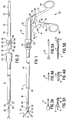
- FIG. 1 An endoscopic surgical instrument 10 in accordance with the present invention is shown generally in Figure 1.
- the main components of the surgical instrument are a slender elongated shaft assembly 12 connected at its proximal end to a handle assembly 14.
- a surgical tool or attachment 7, such as a pair of jaws 9, is connected to the distal end of the shaft assembly 12.
- the shaft assembly enters a patient's body through a cannula and the handle assembly is operated by a surgeon/user to maneuver and actuate the surgical tool.
- a pair of atraumatic Babcock jaws 11 are shown in Figures 3A and 3B and are ideally suited for gripping tissue.
- Other tissue gripping attachments that can be used with the subject invention include a pair of Allis jaws 13 as shown in Figures 4A and 4B and a pair of Pennington jaws 15 as shown in Figures 5A and 5B.
- the jaws are opened and closed for gripping tissue, for example, and can be oriented by rotation about a longitudinal axis of the shaft assembly by operating the handle assembly in a manner described below.
- this assembly includes an outer hollow shaft 16 and an elongated inner hollow shaft 18 disposed within the outer shaft for relative axial reciprocal sliding movement.
- the outer hollow shaft 16 is preferably fabricated from a high temperature-resistant plastic and may be, for example, 10mm in outside diameter to provide an airtight seal when inserted within a conventionally and complementary sized cannula.
- the outer shaft has a tapered front end 20 and an enlarged-diameter rear end 22. The rear end is formed with an interior stepped portion 31 and exterior gripping surfaces 24 that fit over a distal portion of the handle assembly.
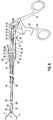
- the outer shaft is normally disposed in its rearward position as shown in Figures 1 and 6 when the surgical instrument is in use to cover a multiple flush port system in the handle assembly that will be described in detail below. However, the outer shaft can slide forwardly over the inner shaft to a position shown in Figure 2 to expose dual flush ports 82 and 86 in the handle assembly for cleaning the surgical instrument. A stop 26 on the inner shaft 18 limits forward movement of the outer shaft.
- the inner shaft 18 may preferably be approximately 5mm in diameter and be made of, for example, a rounded stainless steel shaft covered with a thin layer of hard resin plastic. As best seen in Figure 10, the inner shaft 18 is connected at its proximal end, such as by screw threads 27, to a concentrically mounted hollow barrel cam 25 disposed within the handle assembly. The distal end of the inner shaft terminates in a linkage assembly 28, shown in Figures 1, 6, 7, and 8, for operating the surgical attachment. The linkage assembly is actuated by a pushrod 30 that extends entirely through the inner shaft and the barrel cam, can be moved axially reciprocally relative thereto, and is operably connected to the handle assembly 14 in a manner described below.
- the linkage assembly is best seen in Figures 1 and 6 through 8 and comprises two linkages 32 and a cam link 34 that is secured to the distal end of pushrod 30.
- One linkage 32 is provided for each jaw member 9 of the surgical attachment and includes a pushrod pin 36, an arcuate slot 38 and an engaging pin 40 as shown in Figure 8. (For simplicity of illustration, only one linkage and one jaw are shown in Figures 7 and 8.)
- the pushrod pin 36 fits in a linear slot 42 in cam link 34 and the arcuate slot 38 receives a pin 44 on the cam link.
- the cam link is sandwiched between two identical linkages when assembled and thus has a pin 44 on each side for engaging the arcuate slots of the respective linkages.
- Each jaw member 9 includes a lever arm 15 having a pinhole 17 for receiving engaging pin 40 from one of the linkages and a pivot hole 19.
- a linkage housing 29 secured to the distal end of the inner shaft 18 houses the linkages and the cam link and pivotally supports the jaw members 9 by means of a screw 21 projecting through the pivot holes 19 in each jaw member.
- the pins 44 are integrally formed, for example, by being machined on the cam link and the pins 36 and 40 are integrally formed, for example, by being machined on the linkages.
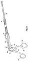
- the handle assembly 14 is shown generally in Figure 1 and comprises a scissors-like actuating mechanism 50 with a stationary leg 52 terminating in a thumb loop 54 and a pivoting leg 56 terminating in a finger loop 58.
- the pivoting leg is operably connected to the pushrod 30 and pivots about a pivot pin 60 when squeezed by the surgeon/user to axially slide the pushrod and actuate the linkage assembly.
- a locking slide control 62 has a channel 63 (shown in phantom lines in Figure 1) for sliding along the pivoting leg and includes an open finger loop 64 for easy manipulation by the finger of the user.
- the slide control has a rear end portion 68 that fits over and embraces the stationary leg 52.
- the rear end portion includes slide control ridges 70 for engaging complimentary ridges 72 on the back surface of the stationary leg, which are shown in Figure 2.
- the locking slide control 62 can be lowered as shown in Figure 9 to engage the slide control ridges 70 with the stationary leg ridges 72 and prevent the pivoting leg from returning to its rest position.
- the actuated jaws can thus be locked in a closed position.
- the stationary leg 52 includes a contoured portion 53 for abutting the pivoting leg 56 and limiting its movement about the pivot pin 60. The contoured portion thus prevents overtravel of the jaws.
- Figures 6, 7 and 10 further provide an internal view of the handle assembly.
- a notch 88 at the upper portion of the pivoting leg 56 receives and secures therein a spherical portion 90 at the proximal end of the pushrod 30.
- the spherical portion is able to rotate within the notch, in the fashion of a ball and socket joint, when the pushrod is rotated about its axis as will be discussed below.
- the leg 56 pivots about pivot pin 60 when squeezed and forces pushrod in the distal, or forward, direction to actuate the linkage assembly and close the attached surgical tool.
- the leg is biased back to its rest position by the force of a compressed coil spring 91 disposed within the handle assembly.
- the barrel cam 25 secured to the inner shaft is supported at its proximal end in a body 76 of the handle assembly by a bushing 93, such as a TEFLON® bearing, disposed in a seat of the body.
- the distal end of the barrel cam is supported by a transition ring 95 and a spanner nut 97.
- the barrel cam has a helical groove 94 on its outer surface.
- An open finger loop slide control mechanism 74 is slidably engaged to the handle assembly and operates a cam driver 96 that projects into the helical groove. As the slide control slides axially, the cam driver runs in the helical groove 94 and causes the barrel cam to rotate about its longitudinal axis.
- the rotating barrel cam in turn rotates the connected inner shaft, the linkage assembly, and the surgical tool attached thereto.
- the pushrod also rotates about its longitudinal axis upon rotation of the barrel cam, which is permitted by the ball and socket connection of the notch 88 and spherical portion 90.
- the pitch of the helical groove 94 can be chosen to regulate the degree of rotation of the barrel cam based on the amount of linear movement of slide control mechanism 74.
- the slide control mechanism and barrel cam assembly can thus provide very fine rotational resolution for precisely orienting the surgical jaws.
- the outer shaft does not rotate as the jaws are oriented by rotational movement of the inner shaft.
- the outer shaft 16 does not move relative to the cannula and an airtight seal therebetween can be maintained.
- the slide control mechanism 74 can be freely manipulated to orient the jaws.
- the surgical instrument is designed to restrain or inhibit rotation of the barrel cam, and thus the jaws, when the handle assembly is fully actuated and gripping tissue.
- the state of being fully actuated is achieved when the jaws are completely closed or closed around the object to be gripped to the point where the jaws cannot be further closed.
- a distal end of the barrel cam 25 includes a flange 110 secured to the barrel cam.
- the flange is positioned immediately adjacent a proximal end of the stationary spanner nut 97 and, when the handle assembly is at rest or is being actuated, i.e., when there is no gripping force on the jaws, rotates freely with the barrel cam when linear movement is imparted to slide control mechanism 74.
- a multiple flush port system 78 is disposed at the distal end of handle assembly body 76 for cleaning and providing improved sterilizability of the instrument.
- the flushing system includes a transition ring 95, or stepped cylindrical collar, having a first cylindrical portion 80 having a distal flush port 82 and a second, larger cylindrical portion 84 with a proximal flush port 86.
- Both distal and proximal flush ports accept cleansing fluid from a male luer, such as a 10cc syringe, for flushing out tissue and fluid after each use of the surgical instrument.
- first and second elastomeric O-rings 90 and 92 provide a secure fit between the transition ring and the back end 22 of outer shaft 16.
- a first sealing ring 99 is positioned between the transition ring 95 and the barrel cam 25, and a second sealing ring 101 is positioned between the pushrod 30 and the barrel cam and abuts a flared portion 103 of the pushrod.
- the sealing rings are made of polytetrafluoroethylene, for example, and are designed to provide an air-tight seal between fluid passages leading from each respective flush port while permitting relative movement between the pushrod 30 and an interior surface of the barrel cam.
- the flared portion acts to seal the fluid passages leading from the distal and proximal flush ports from each other, and also prevents pneumoperitoneal loss in the insufflated body cavity.
- the outer shaft slides axially toward the stop 26 on the inner shaft to expose the distal and proximal flush ports 82 and 86 as shown in Figure 2.
- the barrel cam provides two sets of holes for receiving the cleansing fluid dispersed through the flush ports.
- a first set of holes 100 and 102 align with the flush ports 86 and 82, respectively, when the slide control mechanism 74 is in its rearward-most position, as shown in Figure 10, and a second set of holes 104 and 106 align with the flush ports when the slide control is positioned fully forwardly.
- the flush ports receive the cleansing fluid from the male luer such as a 10cc syringe.
- the distal flush port 82 receives the cleansing fluid for flushing the pushrod 30 and the linkage assembly 28.
- the proximal port 86 receives cleansing fluid for flushing the cam barrel 25 and other components within the handle assembly body 76.
- the barrel cam may be provided with circumferential grooves to allow cleansing fluids to flow into holes 100 and 102 regardless of the rotational positions of the flush ports 86 and 82.
- the present invention provides a novel endoscopic surgical instrument that can be reliably sealed in an cannula to maintain body cavity insufflation.
- the operative elements of the instrument such as tissue gripping jaws, may be rotated easily about the elongated axis of the device to be properly oriented at any time during the surgical procedure, all without disturbing the air-tight seal between the instrument and the cannula. Nevertheless, such rotation of the operative elements is restrained when they are fully actuated.
- the present invention provides substantial improvements over know endoscopic surgical instruments of this type.
Landscapes
- Health & Medical Sciences (AREA)
- Surgery (AREA)
- Life Sciences & Earth Sciences (AREA)
- Medical Informatics (AREA)
- Animal Behavior & Ethology (AREA)
- Engineering & Computer Science (AREA)
- Biomedical Technology (AREA)
- Heart & Thoracic Surgery (AREA)
- Veterinary Medicine (AREA)
- Molecular Biology (AREA)
- Nuclear Medicine, Radiotherapy & Molecular Imaging (AREA)
- General Health & Medical Sciences (AREA)
- Public Health (AREA)
- Ophthalmology & Optometry (AREA)
- Oral & Maxillofacial Surgery (AREA)
- Pathology (AREA)
- Surgical Instruments (AREA)
- Endoscopes (AREA)
Applications Claiming Priority (2)
| Application Number | Priority Date | Filing Date | Title |
|---|---|---|---|
| US08/132,724 US5472439A (en) | 1993-10-06 | 1993-10-06 | Endoscopic surgical instrument with rotatable inner shaft |
| US132724 | 1993-10-06 |
Publications (2)
| Publication Number | Publication Date |
|---|---|
| EP0647433A1 true EP0647433A1 (fr) | 1995-04-12 |
| EP0647433B1 EP0647433B1 (fr) | 1999-08-11 |
Family
ID=22455313
Family Applications (1)
| Application Number | Title | Priority Date | Filing Date |
|---|---|---|---|
| EP94114922A Expired - Lifetime EP0647433B1 (fr) | 1993-10-06 | 1994-09-22 | Instrument endoscopique chirurgical avec tige rotative interne |
Country Status (9)
| Country | Link |
|---|---|
| US (1) | US5472439A (fr) |
| EP (1) | EP0647433B1 (fr) |
| JP (1) | JP3626777B2 (fr) |
| KR (1) | KR950010857A (fr) |
| AT (1) | ATE183064T1 (fr) |
| CA (1) | CA2133627C (fr) |
| DE (1) | DE69419996T2 (fr) |
| TW (1) | TW319686B (fr) |
| ZA (1) | ZA947793B (fr) |
Cited By (5)
| Publication number | Priority date | Publication date | Assignee | Title |
|---|---|---|---|---|
| WO2002071956A1 (fr) * | 2001-03-12 | 2002-09-19 | Karl Storz Gmbh & Co. Kg | Instrument de prehension medical |
| EP2095778A1 (fr) * | 2008-02-26 | 2009-09-02 | Terumo Kabushiki Kaisha | Manipulateur |
| EP2014246A3 (fr) * | 2007-07-13 | 2010-08-04 | Karl Storz GmbH & Co. KG | Instrument médical |
| EP2340774A3 (fr) * | 2002-03-22 | 2011-11-30 | Gyrus ENT, L.L.C. | Appareil chirurgical électrique et procédé pour la fabrication d'un appareil chirurgical électrique |
| CN105662556A (zh) * | 2015-12-30 | 2016-06-15 | 桐庐万禾医疗器械有限公司 | 一种光学异物抓钳 |
Families Citing this family (59)
| Publication number | Priority date | Publication date | Assignee | Title |
|---|---|---|---|---|
| US5984939A (en) | 1989-12-05 | 1999-11-16 | Yoon; Inbae | Multifunctional grasping instrument with cutting member and operating channel for use in endoscopic and non-endoscopic procedures |
| US6063098A (en) * | 1996-12-23 | 2000-05-16 | Houser; Kevin | Articulable ultrasonic surgical apparatus |
| US6051010A (en) * | 1996-12-23 | 2000-04-18 | Ethicon Endo-Surgery, Inc. | Methods and devices for joining transmission components |
| JPH114834A (ja) * | 1997-04-24 | 1999-01-12 | Asahi Optical Co Ltd | 内視鏡用把持具 |
| US6059719A (en) * | 1997-08-06 | 2000-05-09 | Olympus Optical Co., Ltd. | Endoscope system |
| US5976161A (en) * | 1998-01-07 | 1999-11-02 | University Of New Mexico | Tissue everting apparatus and method |
| US6319257B1 (en) * | 1999-12-20 | 2001-11-20 | Kinamed, Inc. | Inserter assembly |
| US6602262B2 (en) * | 2000-06-02 | 2003-08-05 | Scimed Life Systems, Inc. | Medical device having linear to rotation control |
| DE10137122A1 (de) * | 2001-07-30 | 2003-02-27 | Aesculap Ag & Co Kg | Medizinisches Instrument |
| DE10156313A1 (de) * | 2001-11-19 | 2003-06-05 | Wolf Gmbh Richard | Medizinische Zange |
| US7122028B2 (en) * | 2001-12-19 | 2006-10-17 | Allegiance Corporation | Reconfiguration surgical apparatus |
| IL149689A (en) * | 2002-05-15 | 2009-07-20 | Roei Medical Technologies Ltd | An efficient operating mechanism for precise lateral cutting of biological tissues and a method for its use |
| DE10224190B3 (de) * | 2002-05-31 | 2004-01-22 | Richard Wolf Gmbh | Medizinische Zange |
| KR20040041258A (ko) * | 2002-11-09 | 2004-05-17 | 나공찬 | 리섹터스코프 및 그의 전극 어셈블리 |
| US7922739B2 (en) * | 2003-03-28 | 2011-04-12 | Downey Earl C | Surgical instrument with trigger control |
| US7025775B2 (en) * | 2003-05-15 | 2006-04-11 | Applied Medical Resources Corporation | Surgical instrument with removable shaft apparatus and method |
| JP4022526B2 (ja) * | 2004-03-30 | 2007-12-19 | 株式会社東芝 | 医療用器具 |
| US7842045B2 (en) * | 2005-01-19 | 2010-11-30 | Applied Medical Resources Corporation | Single fire vascular clip applier with disposable jaw |
| US8080004B2 (en) * | 2005-10-26 | 2011-12-20 | Earl Downey | Laparoscopic surgical instrument |
| DE102006013979A1 (de) * | 2006-03-15 | 2007-09-20 | Karl Storz Gmbh & Co. Kg | Flexible Hohlwelle für ein medizinisches Instrument |
| US20080027544A1 (en) * | 2006-07-28 | 2008-01-31 | Warsaw Orthopedic Inc. | Instruments and techniques for engaging spinal implants for insertion into a spinal space |
| US7686809B2 (en) * | 2006-09-25 | 2010-03-30 | Stryker Spine | Rod inserter and rod with reduced diameter end |
| US20090270812A1 (en) * | 2007-04-06 | 2009-10-29 | Interlace Medical , Inc. | Access device with enhanced working channel |
| US9095366B2 (en) | 2007-04-06 | 2015-08-04 | Hologic, Inc. | Tissue cutter with differential hardness |
| US8574253B2 (en) | 2007-04-06 | 2013-11-05 | Hologic, Inc. | Method, system and device for tissue removal |
| US20080294179A1 (en) * | 2007-05-12 | 2008-11-27 | Balbierz Daniel J | Devices and methods for stomach partitioning |
| US8758359B2 (en) * | 2007-05-14 | 2014-06-24 | Ethicon, Inc. | Instruments for implanting implantable prostheses |
| US8092474B2 (en) * | 2007-05-21 | 2012-01-10 | Ethicon Endo-Surgery, Inc. | Methods and devices for placement of an intra-abdominal or intra-thoracic appliance through a natural body orifice |
| JP5711656B2 (ja) | 2008-03-31 | 2015-05-07 | アプライド メディカル リソーシーズ コーポレイション | 電気外科システム |
| CA2722566A1 (fr) * | 2008-04-25 | 2009-10-29 | Downey, Earl, C. | Instrument chirurgical laparoscopique |
| TW201018442A (en) * | 2008-11-13 | 2010-05-16 | Yun-Nan Lin | A device for dissecting and cutting in endoscopic surgery |
| US11903602B2 (en) | 2009-04-29 | 2024-02-20 | Hologic, Inc. | Uterine fibroid tissue removal device |
| AU2010295447C1 (en) | 2009-09-17 | 2014-11-27 | Carlos K. Wesley | Hair restoration surgery |
| US9314082B2 (en) | 2009-09-17 | 2016-04-19 | Pilofocus, Inc. | System and method for extraction of hair follicle |
| US9693799B2 (en) | 2009-09-17 | 2017-07-04 | Pilofocus, Inc. | System and method for aligning hair follicle |
| DE102010044982A1 (de) * | 2010-09-10 | 2012-03-15 | Dannoritzer Medizintechnik Gmbh & Co. Kg | Chirurgisches Instrument |
| JP6143362B2 (ja) | 2010-10-01 | 2017-06-07 | アプライド メディカル リソーシーズ コーポレイション | ジョー及び/又は電極、及び電気手術用増幅器を持つ電気手術器具 |
| US10842671B2 (en) | 2010-11-15 | 2020-11-24 | Aquesys, Inc. | Intraocular shunt placement in the suprachoroidal space |
| JP2014534008A (ja) | 2011-10-17 | 2014-12-18 | ピロフォーカス インコーポレイテッド | 毛髪再生 |
| US9808373B2 (en) | 2013-06-28 | 2017-11-07 | Aquesys, Inc. | Intraocular shunt implantation |
| US9610195B2 (en) | 2013-02-27 | 2017-04-04 | Aquesys, Inc. | Intraocular shunt implantation methods and devices |
| USD711712S1 (en) | 2012-02-24 | 2014-08-26 | Cercore Llc | Pair of handles for an instrument or tool |
| US8968298B2 (en) | 2012-03-15 | 2015-03-03 | Covidien Lp | Electrosurgical instrument |
| ES2960913T3 (es) | 2013-11-14 | 2024-03-07 | Aquesys Inc | Insertador de derivación intraocular |
| EP3142583B1 (fr) | 2014-05-16 | 2023-04-12 | Applied Medical Resources Corporation | Système électrochirurgical |
| WO2015184446A2 (fr) | 2014-05-30 | 2015-12-03 | Applied Medical Resources Corporation | Systèmes électrochirurgicaux de scellement et de dissection |
| ES2768761T3 (es) | 2014-12-23 | 2020-06-23 | Applied Med Resources | Sellador y divisor electro-quirúrgico bipolar |
| USD748259S1 (en) | 2014-12-29 | 2016-01-26 | Applied Medical Resources Corporation | Electrosurgical instrument |
| UA122570C2 (uk) | 2015-06-03 | 2020-12-10 | Аквісіс, Інк. | Розміщення ab externo внутрішньоочного шунта |
| DE102015117731A1 (de) * | 2015-10-19 | 2017-04-20 | Karl Storz Gmbh & Co. Kg | Medizinisches Instrument |
| JP2019517366A (ja) | 2016-06-02 | 2019-06-24 | アクシス、インコーポレイテッド | 眼内薬物送達 |
| US11246753B2 (en) | 2017-11-08 | 2022-02-15 | Aquesys, Inc. | Manually adjustable intraocular flow regulation |
| US10952898B2 (en) | 2018-03-09 | 2021-03-23 | Aquesys, Inc. | Intraocular shunt inserter |
| US11135089B2 (en) | 2018-03-09 | 2021-10-05 | Aquesys, Inc. | Intraocular shunt inserter |
| US11864812B2 (en) | 2018-09-05 | 2024-01-09 | Applied Medical Resources Corporation | Electrosurgical generator control system |
| KR20210092263A (ko) | 2018-11-16 | 2021-07-23 | 어플라이드 메디컬 리소시스 코포레이션 | 전기수술용 시스템 |
| CN114467389B (zh) * | 2022-01-29 | 2023-06-13 | 扬州大学 | 一种多功能无人化耕种装置 |
| CN114587487B (zh) * | 2022-03-11 | 2023-07-14 | 常州市康蒂娜医疗科技有限公司 | 一种钳头角度转动操作省力的施夹钳 |
| CN116919576B (zh) * | 2023-09-16 | 2023-12-08 | 武汉半边天医疗技术发展有限公司 | 一种射频超声两用刀 |
Citations (2)
| Publication number | Priority date | Publication date | Assignee | Title |
|---|---|---|---|---|
| EP0537574A2 (fr) * | 1991-10-18 | 1993-04-21 | United States Surgical Corporation | Instrument chirurgical endoscopique |
| EP0555105A1 (fr) * | 1992-02-07 | 1993-08-11 | Symbiosis Corporation | Instrument de chirurgie endoscopique ayant des effecteurs terminaux pivotables |
Family Cites Families (20)
| Publication number | Priority date | Publication date | Assignee | Title |
|---|---|---|---|---|
| US5133727A (en) * | 1990-05-10 | 1992-07-28 | Symbiosis Corporation | Radial jaw biopsy forceps |
| US4258716A (en) * | 1978-02-06 | 1981-03-31 | The University Of Melbourne | Microsurgical instruments |
| US4499899A (en) * | 1983-01-21 | 1985-02-19 | Brimfield Precision, Inc. | Fiber-optic illuminated microsurgical scissors |
| DE3303349A1 (de) * | 1983-02-02 | 1984-08-02 | Reinhold 7230 Schramberg Straub | Chirurgisches instrument zum schneiden von gewebe insb. knorpel |
| US4601290A (en) * | 1983-10-11 | 1986-07-22 | Cabot Medical Corporation | Surgical instrument for cutting body tissue from a body area having a restricted space |
| US4848338A (en) * | 1987-01-20 | 1989-07-18 | Minnesota Mining And Manufacturing Company | Hydraulically operated surgical instrument |
| US4986825A (en) * | 1988-10-11 | 1991-01-22 | Concept, Inc. | Surgical cutting instrument |
| DE9001262U1 (fr) * | 1990-02-05 | 1990-08-09 | Martin, Werner, 7207 Rietheim-Weilheim, De | |
| US5171256A (en) * | 1990-05-10 | 1992-12-15 | Symbiosis Corporation | Single acting disposable laparoscopic scissors |
| US5203785A (en) * | 1990-05-10 | 1993-04-20 | Symbrosis Corporation | Laparoscopic hook scissors |
| FR2668696B1 (fr) * | 1990-11-06 | 1993-02-19 | Ethnor | Instrument chirurgical endoscopique pour la saisie de tissus. |
| US5171257A (en) * | 1991-04-29 | 1992-12-15 | Ferzli George S | Laparoscopic instrument |
| US5176699A (en) * | 1991-06-05 | 1993-01-05 | Harold Markham | Surgical device with double jaw actuation |
| AU2377492A (en) * | 1991-07-16 | 1993-02-23 | Davinci Medical, Inc. | Surgical instrument actuator |
| US5366477A (en) * | 1991-10-17 | 1994-11-22 | American Cyanamid Company | Actuating forces transmission link and assembly for use in surgical instruments |
| CA2075333C (fr) * | 1991-10-18 | 2003-07-22 | Ernie Aranyi | Manche pour instruments chirurgicaux endoscopiques et mecanisme de machoire |
| CA2076331A1 (fr) * | 1991-10-18 | 1993-04-19 | Ernie Aranyi | Instrument chirurgical endoscopique |
| US5281220A (en) * | 1992-01-13 | 1994-01-25 | Blake Joseph W Iii | Endoscopic instrument |
| US5282806A (en) * | 1992-08-21 | 1994-02-01 | Habley Medical Technology Corporation | Endoscopic surgical instrument having a removable, rotatable, end effector assembly |
| US5222973A (en) * | 1992-03-09 | 1993-06-29 | Sharpe Endosurgical Corporation | Endoscopic grasping tool surgical instrument |
-
1993
- 1993-10-06 US US08/132,724 patent/US5472439A/en not_active Expired - Lifetime
-
1994
- 1994-09-22 EP EP94114922A patent/EP0647433B1/fr not_active Expired - Lifetime
- 1994-09-22 DE DE69419996T patent/DE69419996T2/de not_active Expired - Lifetime
- 1994-09-22 AT AT94114922T patent/ATE183064T1/de not_active IP Right Cessation
- 1994-10-04 JP JP26325794A patent/JP3626777B2/ja not_active Expired - Lifetime
- 1994-10-04 CA CA002133627A patent/CA2133627C/fr not_active Expired - Lifetime
- 1994-10-05 KR KR1019940025459A patent/KR950010857A/ko not_active Application Discontinuation
- 1994-10-05 ZA ZA947793A patent/ZA947793B/xx unknown
- 1994-11-16 TW TW083110630A patent/TW319686B/zh active
Patent Citations (2)
| Publication number | Priority date | Publication date | Assignee | Title |
|---|---|---|---|---|
| EP0537574A2 (fr) * | 1991-10-18 | 1993-04-21 | United States Surgical Corporation | Instrument chirurgical endoscopique |
| EP0555105A1 (fr) * | 1992-02-07 | 1993-08-11 | Symbiosis Corporation | Instrument de chirurgie endoscopique ayant des effecteurs terminaux pivotables |
Cited By (10)
| Publication number | Priority date | Publication date | Assignee | Title |
|---|---|---|---|---|
| WO2002071956A1 (fr) * | 2001-03-12 | 2002-09-19 | Karl Storz Gmbh & Co. Kg | Instrument de prehension medical |
| US7014649B2 (en) | 2001-03-12 | 2006-03-21 | Karl Storz Gmbh & Co. Kg | Medical instrument |
| EP2340774A3 (fr) * | 2002-03-22 | 2011-11-30 | Gyrus ENT, L.L.C. | Appareil chirurgical électrique et procédé pour la fabrication d'un appareil chirurgical électrique |
| EP2014246A3 (fr) * | 2007-07-13 | 2010-08-04 | Karl Storz GmbH & Co. KG | Instrument médical |
| US8133244B2 (en) | 2007-07-13 | 2012-03-13 | Karl Storz Gmbh & Co. Kg | Medical instrument |
| EP2095778A1 (fr) * | 2008-02-26 | 2009-09-02 | Terumo Kabushiki Kaisha | Manipulateur |
| EP2444013A1 (fr) * | 2008-02-26 | 2012-04-25 | Terumo Kabushiki Kaisha | Manipulateur |
| US8382790B2 (en) | 2008-02-26 | 2013-02-26 | Terumo Kabushiki Kaisha | Manipulator |
| CN105662556A (zh) * | 2015-12-30 | 2016-06-15 | 桐庐万禾医疗器械有限公司 | 一种光学异物抓钳 |
| CN105662556B (zh) * | 2015-12-30 | 2017-12-05 | 桐庐万禾医疗器械有限公司 | 一种光学异物抓钳 |
Also Published As
| Publication number | Publication date |
|---|---|
| DE69419996D1 (de) | 1999-09-16 |
| DE69419996T2 (de) | 2000-02-24 |
| EP0647433B1 (fr) | 1999-08-11 |
| TW319686B (fr) | 1997-11-11 |
| CA2133627A1 (fr) | 1995-04-07 |
| JP3626777B2 (ja) | 2005-03-09 |
| JPH07204206A (ja) | 1995-08-08 |
| KR950010857A (ko) | 1995-05-15 |
| US5472439A (en) | 1995-12-05 |
| CA2133627C (fr) | 2005-03-29 |
| ATE183064T1 (de) | 1999-08-15 |
| ZA947793B (en) | 1995-05-18 |
Similar Documents
| Publication | Publication Date | Title |
|---|---|---|
| EP0647433B1 (fr) | Instrument endoscopique chirurgical avec tige rotative interne | |
| US6077290A (en) | Endoscopic instrument with removable front end | |
| US5330502A (en) | Rotational endoscopic mechanism with jointed drive mechanism | |
| US5797958A (en) | Endoscopic grasping instrument with scissors | |
| US5797939A (en) | Endoscopic scissors with longitudinal operating channel | |
| US5468250A (en) | Endoscopic mechanism with friction maintaining handle | |
| EP1450698B1 (fr) | Instrument chirurgical | |
| US5827323A (en) | Surgical instrument for endoscopic and general surgery | |
| US5490819A (en) | Articulating endoscopic surgical apparatus | |
| US5984938A (en) | Surgical instrument with jaws and movable internal scissors and method for use thereof | |
| US5478351A (en) | Endoscopic surgical tool with handle and detachable tool assembly | |
| US5603723A (en) | Surgical instrument configured to be disassembled for cleaning | |
| US5984939A (en) | Multifunctional grasping instrument with cutting member and operating channel for use in endoscopic and non-endoscopic procedures | |
| US5282800A (en) | Surgical instrument | |
| US5456695A (en) | Multi-tool surgical apparatus | |
| EP0577423B2 (fr) | Système d'instruments endoscopiques | |
| US5755713A (en) | Laparoscopic instrument assembly including a plurality of instruments | |
| US5782859A (en) | Articulating endoscopic surgical apparatus | |
| US5290308A (en) | Endoscopic instrument | |
| AU2014214765B2 (en) | End effector connection and actuation systems | |
| US20080021278A1 (en) | Surgical device with removable end effector | |
| EP0621009A1 (fr) | Instrument chirurgical | |
| EP0606531A2 (fr) | Dispositif chirurgical endoscopique articulé | |
| EP0582295A2 (fr) | Dispositif chirurgical endoscopique articulé | |
| US20030135151A1 (en) | Powered surgical handpiece with precision suction control |
Legal Events
| Date | Code | Title | Description |
|---|---|---|---|
| PUAI | Public reference made under article 153(3) epc to a published international application that has entered the european phase |
Free format text: ORIGINAL CODE: 0009012 |
|
| AK | Designated contracting states |
Kind code of ref document: A1 Designated state(s): AT BE CH DE DK ES FR GB GR IE IT LI LU NL PT SE |
|
| RAX | Requested extension states of the european patent have changed |
Free format text: SI PAYMENT 940922 |
|
| 17P | Request for examination filed |
Effective date: 19950913 |
|
| 17Q | First examination report despatched |
Effective date: 19980310 |
|
| GRAG | Despatch of communication of intention to grant |
Free format text: ORIGINAL CODE: EPIDOS AGRA |
|
| GRAG | Despatch of communication of intention to grant |
Free format text: ORIGINAL CODE: EPIDOS AGRA |
|
| GRAH | Despatch of communication of intention to grant a patent |
Free format text: ORIGINAL CODE: EPIDOS IGRA |
|
| GRAH | Despatch of communication of intention to grant a patent |
Free format text: ORIGINAL CODE: EPIDOS IGRA |
|
| GRAA | (expected) grant |
Free format text: ORIGINAL CODE: 0009210 |
|
| AK | Designated contracting states |
Kind code of ref document: B1 Designated state(s): AT BE CH DE DK ES FR GB GR IE IT LI LU NL PT SE |
|
| AX | Request for extension of the european patent |
Free format text: SI PAYMENT 19940922 |
|
| PG25 | Lapsed in a contracting state [announced via postgrant information from national office to epo] |
Ref country code: SE Free format text: THE PATENT HAS BEEN ANNULLED BY A DECISION OF A NATIONAL AUTHORITY Effective date: 19990811 Ref country code: NL Free format text: LAPSE BECAUSE OF FAILURE TO SUBMIT A TRANSLATION OF THE DESCRIPTION OR TO PAY THE FEE WITHIN THE PRESCRIBED TIME-LIMIT Effective date: 19990811 Ref country code: LI Free format text: LAPSE BECAUSE OF FAILURE TO SUBMIT A TRANSLATION OF THE DESCRIPTION OR TO PAY THE FEE WITHIN THE PRESCRIBED TIME-LIMIT Effective date: 19990811 Ref country code: IT Free format text: LAPSE BECAUSE OF FAILURE TO SUBMIT A TRANSLATION OF THE DESCRIPTION OR TO PAY THE FEE WITHIN THE PRE;WARNING: LAPSES OF ITALIAN PATENTS WITH EFFECTIVE DATE BEFORE 2007 MAY HAVE OCCURRED AT ANY TIME BEFORE 2007. THE CORRECT EFFECTIVE DATE MAY BE DIFFERENT FROM THE ONE RECORDED.SCRIBED TIME-LIMIT Effective date: 19990811 Ref country code: GR Free format text: LAPSE BECAUSE OF NON-PAYMENT OF DUE FEES Effective date: 19990811 Ref country code: FR Free format text: LAPSE BECAUSE OF FAILURE TO SUBMIT A TRANSLATION OF THE DESCRIPTION OR TO PAY THE FEE WITHIN THE PRESCRIBED TIME-LIMIT Effective date: 19990811 Ref country code: CH Free format text: LAPSE BECAUSE OF FAILURE TO SUBMIT A TRANSLATION OF THE DESCRIPTION OR TO PAY THE FEE WITHIN THE PRESCRIBED TIME-LIMIT Effective date: 19990811 Ref country code: BE Free format text: LAPSE BECAUSE OF FAILURE TO SUBMIT A TRANSLATION OF THE DESCRIPTION OR TO PAY THE FEE WITHIN THE PRESCRIBED TIME-LIMIT Effective date: 19990811 Ref country code: AT Free format text: LAPSE BECAUSE OF FAILURE TO SUBMIT A TRANSLATION OF THE DESCRIPTION OR TO PAY THE FEE WITHIN THE PRESCRIBED TIME-LIMIT Effective date: 19990811 |
|
| REF | Corresponds to: |
Ref document number: 183064 Country of ref document: AT Date of ref document: 19990815 Kind code of ref document: T |
|
| REG | Reference to a national code |
Ref country code: CH Ref legal event code: EP |
|
| PGFP | Annual fee paid to national office [announced via postgrant information from national office to epo] |
Ref country code: FR Payment date: 19990902 Year of fee payment: 6 |
|
| REF | Corresponds to: |
Ref document number: 69419996 Country of ref document: DE Date of ref document: 19990916 |
|
| PGFP | Annual fee paid to national office [announced via postgrant information from national office to epo] |
Ref country code: ES Payment date: 19990917 Year of fee payment: 6 |
|
| PG25 | Lapsed in a contracting state [announced via postgrant information from national office to epo] |
Ref country code: LU Free format text: LAPSE BECAUSE OF NON-PAYMENT OF DUE FEES Effective date: 19990922 |
|
| REG | Reference to a national code |
Ref country code: IE Ref legal event code: FG4D |
|
| PG25 | Lapsed in a contracting state [announced via postgrant information from national office to epo] |
Ref country code: PT Free format text: LAPSE BECAUSE OF FAILURE TO SUBMIT A TRANSLATION OF THE DESCRIPTION OR TO PAY THE FEE WITHIN THE PRESCRIBED TIME-LIMIT Effective date: 19991111 Ref country code: DK Free format text: LAPSE BECAUSE OF FAILURE TO SUBMIT A TRANSLATION OF THE DESCRIPTION OR TO PAY THE FEE WITHIN THE PRESCRIBED TIME-LIMIT Effective date: 19991111 |
|
| NLV1 | Nl: lapsed or annulled due to failure to fulfill the requirements of art. 29p and 29m of the patents act | ||
| EN | Fr: translation not filed | ||
| REG | Reference to a national code |
Ref country code: CH Ref legal event code: PL |
|
| PG25 | Lapsed in a contracting state [announced via postgrant information from national office to epo] |
Ref country code: ES Free format text: LAPSE BECAUSE OF FAILURE TO SUBMIT A TRANSLATION OF THE DESCRIPTION OR TO PAY THE FEE WITHIN THE PRESCRIBED TIME-LIMIT Effective date: 20000217 |
|
| PLBE | No opposition filed within time limit |
Free format text: ORIGINAL CODE: 0009261 |
|
| STAA | Information on the status of an ep patent application or granted ep patent |
Free format text: STATUS: NO OPPOSITION FILED WITHIN TIME LIMIT |
|
| 26N | No opposition filed | ||
| REG | Reference to a national code |
Ref country code: GB Ref legal event code: IF02 |
|
| PGFP | Annual fee paid to national office [announced via postgrant information from national office to epo] |
Ref country code: IE Payment date: 20130925 Year of fee payment: 20 Ref country code: DE Payment date: 20130927 Year of fee payment: 20 |
|
| PGFP | Annual fee paid to national office [announced via postgrant information from national office to epo] |
Ref country code: GB Payment date: 20130927 Year of fee payment: 20 |
|
| REG | Reference to a national code |
Ref country code: DE Ref legal event code: R071 Ref document number: 69419996 Country of ref document: DE |
|
| REG | Reference to a national code |
Ref country code: GB Ref legal event code: PE20 Expiry date: 20140921 |
|
| PG25 | Lapsed in a contracting state [announced via postgrant information from national office to epo] |
Ref country code: DE Free format text: LAPSE BECAUSE OF EXPIRATION OF PROTECTION Effective date: 20140923 |
|
| REG | Reference to a national code |
Ref country code: IE Ref legal event code: MK9A |
|
| PG25 | Lapsed in a contracting state [announced via postgrant information from national office to epo] |
Ref country code: GB Free format text: LAPSE BECAUSE OF EXPIRATION OF PROTECTION Effective date: 20140921 |
|
| PG25 | Lapsed in a contracting state [announced via postgrant information from national office to epo] |
Ref country code: IE Free format text: LAPSE BECAUSE OF EXPIRATION OF PROTECTION Effective date: 20140922 |