EP0647123B1 - Instrument for laparoscopic hysterectomy - Google Patents
Instrument for laparoscopic hysterectomy Download PDFInfo
- Publication number
- EP0647123B1 EP0647123B1 EP93912482A EP93912482A EP0647123B1 EP 0647123 B1 EP0647123 B1 EP 0647123B1 EP 93912482 A EP93912482 A EP 93912482A EP 93912482 A EP93912482 A EP 93912482A EP 0647123 B1 EP0647123 B1 EP 0647123B1
- Authority
- EP
- European Patent Office
- Prior art keywords
- instrument according
- uterine
- rod
- wing
- uterus
- Prior art date
- Legal status (The legal status is an assumption and is not a legal conclusion. Google has not performed a legal analysis and makes no representation as to the accuracy of the status listed.)
- Expired - Lifetime
Links
- 238000009802 hysterectomy Methods 0.000 title claims abstract description 20
- 210000004291 uterus Anatomy 0.000 claims abstract description 35
- 230000008878 coupling Effects 0.000 claims abstract description 23
- 238000010168 coupling process Methods 0.000 claims abstract description 23
- 238000005859 coupling reaction Methods 0.000 claims abstract description 23
- 238000003780 insertion Methods 0.000 claims abstract description 7
- 230000037431 insertion Effects 0.000 claims abstract description 7
- 210000003679 cervix uteri Anatomy 0.000 claims description 6
- 230000000284 resting effect Effects 0.000 claims 1
- 210000001367 artery Anatomy 0.000 abstract description 11
- 238000000034 method Methods 0.000 description 9
- 210000000685 uterine artery Anatomy 0.000 description 8
- 238000011538 abdominal hysterectomy Methods 0.000 description 6
- 238000002224 dissection Methods 0.000 description 4
- 230000000740 bleeding effect Effects 0.000 description 3
- 201000009273 Endometriosis Diseases 0.000 description 2
- 210000003815 abdominal wall Anatomy 0.000 description 2
- 210000004204 blood vessel Anatomy 0.000 description 2
- 238000010276 construction Methods 0.000 description 2
- 210000003717 douglas' pouch Anatomy 0.000 description 2
- 210000004303 peritoneum Anatomy 0.000 description 2
- 230000002980 postoperative effect Effects 0.000 description 2
- 238000001356 surgical procedure Methods 0.000 description 2
- 208000032544 Cicatrix Diseases 0.000 description 1
- NIPNSKYNPDTRPC-UHFFFAOYSA-N N-[2-oxo-2-(2,4,6,7-tetrahydrotriazolo[4,5-c]pyridin-5-yl)ethyl]-2-[[3-(trifluoromethoxy)phenyl]methylamino]pyrimidine-5-carboxamide Chemical compound O=C(CNC(=O)C=1C=NC(=NC=1)NCC1=CC(=CC=C1)OC(F)(F)F)N1CC2=C(CC1)NN=N2 NIPNSKYNPDTRPC-UHFFFAOYSA-N 0.000 description 1
- 206010028980 Neoplasm Diseases 0.000 description 1
- 206010034238 Pelvic adhesions Diseases 0.000 description 1
- 208000005646 Pneumoperitoneum Diseases 0.000 description 1
- 208000035965 Postoperative Complications Diseases 0.000 description 1
- 210000001015 abdomen Anatomy 0.000 description 1
- 230000003187 abdominal effect Effects 0.000 description 1
- 239000008280 blood Substances 0.000 description 1
- 210000004369 blood Anatomy 0.000 description 1
- 210000004190 broad ligament Anatomy 0.000 description 1
- 201000011510 cancer Diseases 0.000 description 1
- 238000011161 development Methods 0.000 description 1
- 230000018109 developmental process Effects 0.000 description 1
- 238000006073 displacement reaction Methods 0.000 description 1
- 238000002674 endoscopic surgery Methods 0.000 description 1
- 238000001839 endoscopy Methods 0.000 description 1
- 206010016629 fibroma Diseases 0.000 description 1
- 210000000056 organ Anatomy 0.000 description 1
- 208000025661 ovarian cyst Diseases 0.000 description 1
- 230000007170 pathology Effects 0.000 description 1
- 230000011514 reflex Effects 0.000 description 1
- 210000001659 round ligament Anatomy 0.000 description 1
- 231100000241 scar Toxicity 0.000 description 1
- 230000037387 scars Effects 0.000 description 1
- 239000007787 solid Substances 0.000 description 1
- 230000001954 sterilising effect Effects 0.000 description 1
- 238000004659 sterilization and disinfection Methods 0.000 description 1
- 238000009805 subtotal hysterectomy Methods 0.000 description 1
- 238000009804 total hysterectomy Methods 0.000 description 1
- 238000011282 treatment Methods 0.000 description 1
- 210000001215 vagina Anatomy 0.000 description 1
Images




Classifications
-
- A—HUMAN NECESSITIES
- A61—MEDICAL OR VETERINARY SCIENCE; HYGIENE
- A61B—DIAGNOSIS; SURGERY; IDENTIFICATION
- A61B17/00—Surgical instruments, devices or methods
- A61B17/28—Surgical forceps
- A61B17/29—Forceps for use in minimally invasive surgery
-
- A—HUMAN NECESSITIES
- A61—MEDICAL OR VETERINARY SCIENCE; HYGIENE
- A61B—DIAGNOSIS; SURGERY; IDENTIFICATION
- A61B17/00—Surgical instruments, devices or methods
- A61B17/02—Surgical instruments, devices or methods for holding wounds open, e.g. retractors; Tractors
- A61B17/0218—Surgical instruments, devices or methods for holding wounds open, e.g. retractors; Tractors for minimally invasive surgery
-
- A—HUMAN NECESSITIES
- A61—MEDICAL OR VETERINARY SCIENCE; HYGIENE
- A61B—DIAGNOSIS; SURGERY; IDENTIFICATION
- A61B17/00—Surgical instruments, devices or methods
- A61B17/42—Gynaecological or obstetrical instruments or methods
- A61B17/4241—Instruments for manoeuvring or retracting the uterus, e.g. during laparoscopic surgery
-
- A—HUMAN NECESSITIES
- A61—MEDICAL OR VETERINARY SCIENCE; HYGIENE
- A61B—DIAGNOSIS; SURGERY; IDENTIFICATION
- A61B17/00—Surgical instruments, devices or methods
- A61B17/28—Surgical forceps
- A61B17/29—Forceps for use in minimally invasive surgery
- A61B2017/2926—Details of heads or jaws
- A61B2017/2927—Details of heads or jaws the angular position of the head being adjustable with respect to the shaft
-
- A—HUMAN NECESSITIES
- A61—MEDICAL OR VETERINARY SCIENCE; HYGIENE
- A61B—DIAGNOSIS; SURGERY; IDENTIFICATION
- A61B17/00—Surgical instruments, devices or methods
- A61B17/28—Surgical forceps
- A61B17/29—Forceps for use in minimally invasive surgery
- A61B2017/2926—Details of heads or jaws
- A61B2017/2932—Transmission of forces to jaw members
- A61B2017/2933—Transmission of forces to jaw members camming or guiding means
- A61B2017/2936—Pins in guiding slots
-
- A—HUMAN NECESSITIES
- A61—MEDICAL OR VETERINARY SCIENCE; HYGIENE
- A61B—DIAGNOSIS; SURGERY; IDENTIFICATION
- A61B17/00—Surgical instruments, devices or methods
- A61B17/28—Surgical forceps
- A61B17/29—Forceps for use in minimally invasive surgery
- A61B2017/2926—Details of heads or jaws
- A61B2017/2932—Transmission of forces to jaw members
- A61B2017/2939—Details of linkages or pivot points
Definitions
- the present invention relates to an instrument for laparoscopic vaginal hysterectomy, including laparoscope-assisted sub-total and total hysterectomy comprising a uterine rotator.
- Hysterectomy is one of the surgical operations most frequently performed on women. On average the uterus is removed in one in three women.
- Abdominal hysterectomy is generally performed in particular when the uterine volume is large, when extensive pelvic adhesions are present or expected, and when other pathology such as ovarian cysts, extensive endometriosis or cancer are present.
- Vaginal hysterectomy has the advantage relative to abdominal hysterectomy of a lower post-operative morbidity and the absence of abdominal scars.
- Endoscopic surgery has been employed more and more in recent years due to technical developments in the area of video-endoscopy and in the area of lasers as bloodless, precision cutting instruments in addition to persufflation techniques, such as described in EP-A-0 350 499.
- EP-A-464 463 which is used as basis for the preamble of claim 1, discloses an instrument for manipulating an organ.
- an instrument for laparoscopic vaginal hysterectomy according to the invention as defined in claim 1 which comprises a uterine rotator comprising a rod with a uterine end for insertion into the uterus and a control end.
- Fixing and controlled rotation of the uterus is further improved if more preferably the rod is provided with two wings which in that case are preferably movable diametrically relative to each other in and out of the uterine end of the rod.
- each wing preferably comprises two wing portions connected for mutual rotation, whereof a first wing portion is rotatably connected to a rod tip and whereof the second wing portion is connected to the coupling means.
- first wing portion is rotatably connected to a rod tip
- second wing portion is connected to the coupling means.
- both second wing portions lie in reflex position inside both first wing portions in the folded-out position, thereby avoiding that the second wing portions or their coupling to the coupling means touch the fundus of the uterus, whereby damage or perforation is avoided.
- Optimal insertion of the uterine rotator into the uterus is obtained when in a folded-in position the wing more preferably lies enveloped within a rod. It is recommended for this purpose that the rod is provided with a recess for receiving a folded-in wing. For optimal insertion of the uterine end it is necessary for this purpose that in folded-in position the uterine end has a round, for instance oval and circular, shape in cross section.
- the coupling means comprise a coupling element received in the hollow rod.
- the coupling element is a slide strip
- the coupling element is a threaded strip.
- the rod is further provided with at least one hinge whereby the uterine end can pivot and the front part of the uterus can be placed in front of the endoscope.
- the hinge is located at a distance from the tip of the uterine end such that the pivot point lies at the height of the cervix of the uterus, parts located forwardly of the uterus can, by both retroflexion and anterioflexion, be optimally viewed with the endoscope and become accessible to surgical instruments.
- the pivoting movement can be performed transversely of as well as in the plane of the wing or wings and the coupling means, including the coupling element. If however the pivoting movement is followed by a rotation movement, a pivoting movement in the plane of the wing or wings and the coupling means takes preference from the point of view of surgical technique.
- the uterine end is connected rotatably via the rotation means to the control end.
- the advantage is herein moreover achieved that through a combination of retroflexion or anterioflexion and rotation through about 90° the lateral uterine blood vessels can be placed in a posterior or anterior position, whereby the laparoscopic hysterectomy is facilitated considerably.
- the secondary openings in the abdominal wall for the instruments can moreover be arranged at a lower level, and for instance inside the so-called bikini line, whereby this surgical approach provides a considerable aesthetic advantage.
- a fornix presentor is guided along the rod of the uterine rotator.
- the greatest problem in laparoscopic vaginal hysterectomy is bleeding from the uterine artery. Under laparoscopic control, however, it is safe and easy to clamp the uterine artery along the vaginal side whereby bleeding can be avoided.
- an artery forceps provided with a handle and mutually reciprocating jaws which is inserted via the vaginal vault may be used.
- the jaws are for example 1-3 cm long.
- the shaft of the artery forceps is preferably curved.
- the artery forceps according to the invention can thus be used in combination with the uterine rotator and can remain in place when the uterus is removed.
- An optimal artery forceps is obtained if more preferably each of the jaws pivots around one of the hinge elements lying at a mutual distance.
- Figure 1 shows an instrument set 1 according to the invention for laparoscopic vaginal hysterectomy. It is a uterine rotator 2 which comprises a hollow rod 3 with a uterine end 4 for insertion into the uterus and a control end 5. The uterine rotator 2 further comprises two wings 6 and 7 outwardly movable diametrically in relation to each other.
- Each wing 6 and 7 comprises a first wing portion 8 that is pivotally connected to a rod tip 10, and a second wing portion which on one side is pivotally connected to the first wing portion 8 and on the other side via a hinge piece 11 to coupling means comprised of a flexible coupling element 12 and guided in the hollow rod, which coupling element 12 has the form of a threaded strip, for which purpose the free end 13 is provided with a thread 14 onto which a nut 15 is rotated and supports on the rod 3.
- the coupling element 12 is pressed to a position in which the wings 6 and 7 are folded inward. In inward folded position the uterine end 4 has a round cross section.
- the rod 3 is provided with a hinge 53 which can be actuated with a pivot rod 54 which is guided in the hollow rod 3 and ends in a control member 55 slidably guided in a slotted hole 56.
- the uterine end 4 can, as shown in figure 2, thus be pivoted downward through up to 70°, preferably through more than about 30°, whereby the ventral side of the uterus can be oriented toward the stationary endoscope 51 (figure 8).
- figure 3 likewise shows the rotator 2 in top view.
- Figure 5 shows an instrument set 29 according to the invention which comprises a uterine rotator 30 with a single wing 31 the construction of which substantially corresponds with the wing 18 of figure 2.
- the wing portion 21 is however pivotally connected to a fork-like uterine end 52 and a slide strip 32 is guided in a guide path 34 arranged in a solid rod 33.
- the uterine rotators 2 and 30 are preferably curved.
- the wings moreover each have a shape which enables good and certain contact with the uterine inner wall substantially without causing too great damage.
- FIG. 6 shows an artery forceps 35.
- the artery forceps has a curved hollow shaft 36 in which is guided a rod 38 controllable with finger grips 37.
- the rod 38 is coupled to both mutually reciprocating jaws 39 and 40 via the links 41 and 42 respectively.
- the jaws 39 and 40 are urged towards each other using a spring 43.
- Figure 7 shows another artery forceps 44 wherein the jaws 45 and 46 are movable with a rod 47 of which a pin 48 is received in slotted holes 49 respectively 50 arranged in the angular jaws 45 and 46.
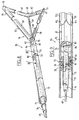
- FIGS 8 and 9 show another uterine rotator 55 according to the invention which likewise comprises a uterine end 56 for insertion into the uterus having two wings 57 and 58 which comprise semi-tubular first wing portions 59 and 60 which are hingedly connected to semi-tubular respective second wing portions 61 and 62.
- the first wing portions 59 and 60 are connected via a hinge 63, 64 to the rod 65 and on the other side via hinges 66, 67 to the second wing portions 61, 62 which are connected via a hinge 68 to the coupling means comprising a rod 69.
- the first wing portions 59 and 60 are provided on their free end with a cap part 70, 71.
- Rod 65 is constructed from a rear end 72, a central portion 74 connected thereto via a hinge 73 and a rotatable forward portion 75.
- the rod 69 for controlling the wings 57 and 58, a rotation tube 76 for causing the front portion 75 to rotate relative to the central portion 74 and a pivot tube 77 for causing the central portion 74 to pivot relative to the rear portion 72.
- the pivot tube 77 comprises on its leading end 78 a bevel gear 79 which co-acts with a bevel gear 80 fixed onto the pivot shaft 81 to which a part 82 of the central portion 74 inserted into the rear end 72 is non-releasably connected. Due to a rotation of pivot tube 77 the pivot shaft 81 will also rotate via the bevel gear pair 79, 80, whereby the central portion 74 pivots independently of the rotation of pivot tube 77.
- Figure 10 shows the operative technique with the uterine rotator of figure 1.
- a video endoscope 51 which is provided with a CO 2 laser (1060 Sharplan, Laser Industry Limited, Tel Aviv, Israel), coupled to an operative laparoscope with an internal diameter of at least 7 mm (Stortz, Germany), which is equipped with a persufflator (EP-A-0 350 499), whereby a constant pneumoperitoneum is made possible even during excessive aspiration, for example as a result of bleeding or after the vagina has been opened, is inserted via the abdominal wall to a position close to the uterus. Two or three additional working channels are further arranged in the abdomen.
- the uterosacrals are then almost but not entirely transected and the douglas pouch incised up to the vaginal vault. If pelvic endometriosis is present this is first removed. The round ligaments are then coagulated, transected, the peritoneum is opened and the bladder moved aside. The ligamentum ovarium veinm is transected. Following dissection of the parametria the uterine artery is clamped with an artery forceps according to the invention.
- vaginal wall is closed.
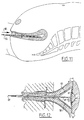
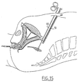
- Figures 11-15 show the operative technique using the uterine rotator as shown in figures 9 and 10.
- FIG 11 a side view
- the uterine rotator 55 is placed as according to arrow 85 into the uterus with folded-in wings as a cylindrical rod.
- Figure 12 (a top view) shows the situation after the wings 57 and 58 are spread by operating the rod 69.
- an angle ⁇ smaller than 180° but greater than 90° is enclosed between the second wing portions 61 and 62, so that the second wing portions 61 and 62 and rod 69 can make substantially no contact with the fundus of the uterus.
- Figures 13 and 14 show in combination the retroflexion-rotation approach and figures 13 and 15 the anterioflexion-rotation approach of the operative technique.
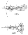
- Figures 16 and 17 show a uterine rotator 86 which is provided with a fornix presentor 88 which is slidable along the rod 87 and comprises a sleeve coupling 89 with a passage 90 through which passes the rod 87 and a collar 91 which diverges in the direction of the uterus and which grips over the cervix.
- Laparoscopic dissection of the cervix is thus simplified, as also, through localizing of the vaginal walls, is dissection of the uterine artery, namely the ramus vaginalis.
- the time duration of the surgical procedure can remain limited (up to less than 60 minutes) to the time for a vaginal or abdominal hysterectomy. Blood loss is moreover greatly reduced, which is an indirect indication of a safer operation.
- the postoperative morbidity evaluated on the basis of the occurrence of bowel sounds is considerably lower (vaginal hysterectomy [VH] mean: 1.3 days, 25-70th percentile: 1-2 days; abdominal hysterectomy [AH] mean: 2.5 days, 25-70th percentile: 2-3 days).
- the hospital stay is shorter (VH 4.5 days as opposed to AH 7.3 days). No post operative complications have been noted.
Landscapes
- Health & Medical Sciences (AREA)
- Surgery (AREA)
- Life Sciences & Earth Sciences (AREA)
- Biomedical Technology (AREA)
- Medical Informatics (AREA)
- Veterinary Medicine (AREA)
- Public Health (AREA)
- Engineering & Computer Science (AREA)
- General Health & Medical Sciences (AREA)
- Heart & Thoracic Surgery (AREA)
- Nuclear Medicine, Radiotherapy & Molecular Imaging (AREA)
- Molecular Biology (AREA)
- Animal Behavior & Ethology (AREA)
- Gynecology & Obstetrics (AREA)
- Pregnancy & Childbirth (AREA)
- Reproductive Health (AREA)
- Ophthalmology & Optometry (AREA)
- Surgical Instruments (AREA)
- Endoscopes (AREA)
Abstract
Description
Claims (17)
- Instrument for laparoscopic vaginal hysterectomy which comprises a uterine rotator (2) comprising:a rod (3) with a uterine end (4) for insertion into the uterus and a control end (5), and with at least one foldable wing (6, 7) movable in and out of said uterine end which in a folded-out position makes contact with the inner wall of the uterus and which is connected via coupling means (12) to a control member (55) located at the control end (5) for resting and/or rotating the uterus, wherein the foldable wing (6, 7) is joined to the uterine end by means of hinges, characterized in that the axis of the hinges of the foldable wing (6, 7) lies in the plane of the foldable wing and is positioned transverse to the length of the wing (6, 7) and in that the side of the foldable wing facing the inner wall of the uterus is rounded such that the foldable wing does not cause damage to the uterus.
- Instrument according to claim 1, wherein the rod (3) is provided with two foldable wings (6, 7).
- Instrument according to claim 2, wherein the foldable wings (6, 7) are movable outward from the rod (3) diametrically in relation to each other.
- Instrument according to claims 1-3, wherein a foldable wing (6, 7) comprises two wing portions (8,9) connected for mutual rotation, whereof a first wing portion (8) is rotatably connected to a rod tip and whereof the second wing portion (9) is connected to the coupling means (12).
- Instrument according to claim 4, wherein in folded-in position the second wing portions (61, 62) are enclosed by the first wing portions (59, 60).
- Instrument according to claim 4 or 5, wherein in folded-out position an angle smaller than 180° and greater than 90° is enclosed between both adjoining second wing portions (61, 62).
- Instrument according to claim 1-6, wherein in a folded-in position the foldable wing (61, 62) lies enveloped within a rod.
- Instrument according to claim 7, wherein the rod (65) is provided with a recess for receiving a folded-in foldable wing.
- Instrument according to claims 1-8, wherein in folded-in position the uterine end has a sectionally round shape.
- Instrument according to claims 1-9, wherein the coupling means (12) comprise a coupling element such as a slide strip or a threaded strip received in the hollow rod (3).
- Instrument according to claims 1-10, wherein the rod is a curved rod.
- Instrument according to claims 1-11, wherein the uterine end is connected via at least one hinge to the control end.
- Instrument according to claim 12, wherein the hinge is located at a distance from the tip of the uterine end such that the pivot point lies at the height of the cervix of the uterus.
- Instrument according to claim 12 or 13, wherein the pivoting movement takes place immediately forward of the foldable wing or the foldable wings and the coupling means.
- Instrument according to claims 1-14, wherein the uterine end is rotatably connected to the control end via the rotation means.
- Instrument according to claims 1-14, wherein the uterine end is connected to the control end via two hinges moving transversely of each other.
- Instrument according to claims 1-16, wherein the uterine rotator is provided with a fornix presentor guided on the rod.
Applications Claiming Priority (3)
| Application Number | Priority Date | Filing Date | Title |
|---|---|---|---|
| NL9201118 | 1992-06-24 | ||
| NL9201118A NL9201118A (en) | 1992-06-24 | 1992-06-24 | TOOL KIT FOR LAPAROSCOPIC VAGINAL HYSTERECTOMY. |
| PCT/BE1993/000040 WO1994000061A1 (en) | 1992-06-24 | 1993-06-23 | Instrument set for laparoscopic hysterectomy |
Publications (2)
| Publication Number | Publication Date |
|---|---|
| EP0647123A1 EP0647123A1 (en) | 1995-04-12 |
| EP0647123B1 true EP0647123B1 (en) | 1998-04-29 |
Family
ID=19860964
Family Applications (1)
| Application Number | Title | Priority Date | Filing Date |
|---|---|---|---|
| EP93912482A Expired - Lifetime EP0647123B1 (en) | 1992-06-24 | 1993-06-23 | Instrument for laparoscopic hysterectomy |
Country Status (7)
| Country | Link |
|---|---|
| US (1) | US5662676A (en) |
| EP (1) | EP0647123B1 (en) |
| JP (1) | JPH08500990A (en) |
| AU (1) | AU4301593A (en) |
| DE (1) | DE69318299T2 (en) |
| NL (1) | NL9201118A (en) |
| WO (1) | WO1994000061A1 (en) |
Families Citing this family (207)
| Publication number | Priority date | Publication date | Assignee | Title |
|---|---|---|---|---|
| DE4303274C2 (en) * | 1993-02-05 | 1997-02-06 | Wolf Gmbh Richard | Endoscopic instrument |
| US6572631B1 (en) | 1993-10-22 | 2003-06-03 | Gynetech Pty Ltd. | Transvaginal tube as an aid to laparoscopic surgery |
| US5643285A (en) * | 1994-10-18 | 1997-07-01 | Blairden Precision Instruments, Inc. | Vaginal extender for colpotomy surgery |
| IL112107A (en) * | 1994-12-21 | 2001-01-28 | Laser Ind Ltd | Device for treating the interior of body cavities with laser energy |
| DE19603981C2 (en) * | 1996-02-05 | 1998-11-05 | Wolf Gmbh Richard | Medical instrument for uterine manipulation |
| US6152874A (en) * | 1996-04-26 | 2000-11-28 | Genzyme Corporation | Adjustable multi-purpose coronary stabilizing retractor |
| EP2138132B1 (en) * | 1997-12-29 | 2012-06-06 | The Cleveland Clinic Foundation | Remote manipulation system for remotely manipulating an associated medical device |
| US6530952B2 (en) * | 1997-12-29 | 2003-03-11 | The Cleveland Clinic Foundation | Bioprosthetic cardiovascular valve system |
| US5904649A (en) * | 1998-04-03 | 1999-05-18 | Andrese; Craig A. | Organ retractors |
| US6471692B1 (en) | 1998-06-24 | 2002-10-29 | Laser Industries Ltd. | System and method for manipulating movement of an energy emitting device within a body cavity |
| US6187000B1 (en) * | 1998-08-20 | 2001-02-13 | Endius Incorporated | Cannula for receiving surgical instruments |
| US6254601B1 (en) * | 1998-12-08 | 2001-07-03 | Hysterx, Inc. | Methods for occlusion of the uterine arteries |
| DE19920869A1 (en) * | 1999-05-06 | 2000-12-07 | Storz Karl Gmbh & Co Kg | Retractor for use in endoscopic surgery, medical instrument for inserting a retractor, and method for using a retractor in endoscopic surgery |
| SK285226B6 (en) * | 1999-09-13 | 2006-09-07 | Jozef Hlucháň | Laparoscopic dissector, especially for laparoscopic hysterectomy |
| US20030120306A1 (en) * | 2000-04-21 | 2003-06-26 | Vascular Control System | Method and apparatus for the detection and occlusion of blood vessels |
| US7223279B2 (en) * | 2000-04-21 | 2007-05-29 | Vascular Control Systems, Inc. | Methods for minimally-invasive, non-permanent occlusion of a uterine artery |
| US6471644B1 (en) | 2000-04-27 | 2002-10-29 | Medtronic, Inc. | Endoscopic stabilization device and method of use |
| US6679886B2 (en) | 2000-09-01 | 2004-01-20 | Synthes (Usa) | Tools and methods for creating cavities in bone |
| US6635065B2 (en) * | 2000-11-16 | 2003-10-21 | Vascular Control Systems, Inc. | Doppler directed suture ligation device and method |
| US6638286B1 (en) | 2000-11-16 | 2003-10-28 | Vascular Control Systems, Inc. | Doppler directed suture ligation device and method |
| JP4227415B2 (en) * | 2001-03-28 | 2009-02-18 | ヴァスキュラー・コントロール・システムズ・インコーポレーテッド | Method and apparatus for detecting and ligating uterine arteries |
| US7354444B2 (en) | 2001-03-28 | 2008-04-08 | Vascular Control Systems, Inc. | Occlusion device with deployable paddles for detection and occlusion of blood vessels |
| KR100476001B1 (en) * | 2001-06-14 | 2005-03-10 | 주식회사 엘지생활건강 | Hair-gel composition |
| US20030176883A1 (en) * | 2002-03-12 | 2003-09-18 | Sauer Jude S | Tissue manipulation apparatus and method of use |
| US7207996B2 (en) * | 2002-04-04 | 2007-04-24 | Vascular Control Systems, Inc. | Doppler directed suturing and compression device and method |
| CA2483906C (en) * | 2002-05-09 | 2011-01-25 | Tyco Healthcare Group Lp | Organ retractor and method of using the same |
| ES2333215T3 (en) * | 2002-05-09 | 2010-02-18 | Tyco Healthcare Group Lp | ENDOSCOPIC ORGAN RETRACTOR. |
| WO2004032757A2 (en) * | 2002-10-04 | 2004-04-22 | Tyco Healthcare Group, Lp | Endoscopic retractor |
| US7172603B2 (en) * | 2002-11-19 | 2007-02-06 | Vascular Control Systems, Inc. | Deployable constrictor for uterine artery occlusion |
| US20040097961A1 (en) * | 2002-11-19 | 2004-05-20 | Vascular Control System | Tenaculum for use with occlusion devices |
| US7322935B2 (en) * | 2003-01-22 | 2008-01-29 | Medcanica, Llc | Endoscopic retractor |
| US7404821B2 (en) * | 2003-01-30 | 2008-07-29 | Vascular Control Systems, Inc. | Treatment for post partum hemorrhage |
| US7651511B2 (en) * | 2003-02-05 | 2010-01-26 | Vascular Control Systems, Inc. | Vascular clamp for caesarian section |
| EP3170459A1 (en) | 2003-03-11 | 2017-05-24 | Covidien LP | Clip applying apparatus with angled jaw |
| US7333844B2 (en) * | 2003-03-28 | 2008-02-19 | Vascular Control Systems, Inc. | Uterine tissue monitoring device and method |
| US20040202694A1 (en) * | 2003-04-11 | 2004-10-14 | Vascular Control Systems, Inc. | Embolic occlusion of uterine arteries |
| US20050143690A1 (en) * | 2003-05-01 | 2005-06-30 | High Kenneth A. | Cystotomy catheter capture device and methods of using same |
| US7169180B2 (en) * | 2003-09-03 | 2007-01-30 | Brennan William A | System and method for breast augmentation |
| US8092527B2 (en) | 2003-09-03 | 2012-01-10 | Brennan William A | System and method for breast augmentation |
| WO2005046491A1 (en) * | 2003-11-12 | 2005-05-26 | Applied Medical Resources Corporation | Overmolded grasper jaw |
| US7325546B2 (en) * | 2003-11-20 | 2008-02-05 | Vascular Control Systems, Inc. | Uterine artery occlusion device with cervical receptacle |
| US7686817B2 (en) * | 2003-11-25 | 2010-03-30 | Vascular Control Systems, Inc. | Occlusion device for asymmetrical uterine artery anatomy |
| CA2580931C (en) | 2004-09-23 | 2013-05-07 | Tyco Healthcare Group Lp | Clip applying apparatus and ligation clip |
| US9763668B2 (en) | 2004-10-08 | 2017-09-19 | Covidien Lp | Endoscopic surgical clip applier |
| JP4783372B2 (en) | 2004-10-08 | 2011-09-28 | タイコ ヘルスケア グループ エルピー | Device for applying a surgical clip |
| JP5047799B2 (en) | 2004-10-08 | 2012-10-10 | タイコ ヘルスケア グループ リミテッド パートナーシップ | Endoscopic surgical clip applier |
| US7819886B2 (en) | 2004-10-08 | 2010-10-26 | Tyco Healthcare Group Lp | Endoscopic surgical clip applier |
| US8409222B2 (en) | 2004-10-08 | 2013-04-02 | Covidien Lp | Endoscopic surgical clip applier |
| US7875036B2 (en) * | 2004-10-27 | 2011-01-25 | Vascular Control Systems, Inc. | Short term treatment for uterine disorder |
| US7758640B2 (en) * | 2004-12-16 | 2010-07-20 | Valvexchange Inc. | Cardiovascular valve assembly |
| US20060135887A1 (en) * | 2004-12-20 | 2006-06-22 | Sampson Russel M | Uterine sound |
| US7862565B2 (en) | 2005-05-12 | 2011-01-04 | Aragon Surgical, Inc. | Method for tissue cauterization |
| US8696662B2 (en) | 2005-05-12 | 2014-04-15 | Aesculap Ag | Electrocautery method and apparatus |
| US8728072B2 (en) | 2005-05-12 | 2014-05-20 | Aesculap Ag | Electrocautery method and apparatus |
| US9339323B2 (en) | 2005-05-12 | 2016-05-17 | Aesculap Ag | Electrocautery method and apparatus |
| US20060271037A1 (en) * | 2005-05-25 | 2006-11-30 | Forcept, Inc. | Assisted systems and methods for performing transvaginal hysterectomies |
| US7641651B2 (en) * | 2005-07-28 | 2010-01-05 | Aragon Surgical, Inc. | Devices and methods for mobilization of the uterus |
| EP1749479A1 (en) * | 2005-08-02 | 2007-02-07 | Marco Gandini | Retractor instrument |
| US20070049973A1 (en) * | 2005-08-29 | 2007-03-01 | Vascular Control Systems, Inc. | Method and device for treating adenomyosis and endometriosis |
| US20070142752A1 (en) * | 2005-12-20 | 2007-06-21 | Robert Kotmel | Uterine cavity length measurement |
| US8007449B2 (en) * | 2005-12-20 | 2011-08-30 | Cytyc Corporation | Method and apparatus for uterine cavity length measurement |
| USD625009S1 (en) | 2006-03-24 | 2010-10-05 | Tyco Healthcare Group Lp | Surgical clip applier |
| USD629101S1 (en) | 2006-03-24 | 2010-12-14 | Tyco Healthcare Group Lp | Surgical clip applier |
| US8574229B2 (en) | 2006-05-02 | 2013-11-05 | Aesculap Ag | Surgical tool |
| US20080004696A1 (en) * | 2006-06-29 | 2008-01-03 | Valvexchange Inc. | Cardiovascular valve assembly with resizable docking station |
| US8690892B2 (en) * | 2006-08-30 | 2014-04-08 | Syed Rizvi | Postpartum uterine manipulators and methods of use thereof |
| EP1913881B1 (en) | 2006-10-17 | 2014-06-11 | Covidien LP | Apparatus for applying surgical clips |
| CA2675376C (en) * | 2007-01-18 | 2012-07-10 | Valvexchange Inc. | Tools for removal and installation of exchangeable cardiovascular valves |
| US8382773B2 (en) | 2007-03-26 | 2013-02-26 | Covidien Lp | Endoscopic surgical clip applier |
| CA2682958C (en) | 2007-04-11 | 2015-11-10 | Tyco Healthcare Group Lp | Surgical clip applier |
| WO2008136024A1 (en) * | 2007-05-04 | 2008-11-13 | Sofar Spa | Uterine manipulator |
| WO2009026272A1 (en) | 2007-08-21 | 2009-02-26 | Valvexchange Inc. | Method and apparatus for prosthetic valve removal |
| US8118826B2 (en) * | 2007-09-27 | 2012-02-21 | Swan Valley Medical, Incorporated | Method of performing a suprapubic transurethral cystostomy and associated procedures and apparatus therefor |
| US8382785B2 (en) * | 2007-09-27 | 2013-02-26 | Swan Valley Medical Incorporated | Apparatus and method for performing cystotomy procedures |
| EP2197336A2 (en) * | 2007-10-07 | 2010-06-23 | EZ Surgical Ltd. | Laparoscopic tissue retractor |
| WO2009073619A2 (en) * | 2007-11-30 | 2009-06-11 | New England Association Of Gynecologic Laparoscopists, Llp | Transcervical excision and removal of tissue |
| US8870867B2 (en) | 2008-02-06 | 2014-10-28 | Aesculap Ag | Articulable electrosurgical instrument with a stabilizable articulation actuator |
| US8764630B2 (en) * | 2008-05-19 | 2014-07-01 | Olympus Medical Systems Corp. | Endoscopic surgical procedure and surgical apparatus |
| US20110208212A1 (en) | 2010-02-19 | 2011-08-25 | Zergiebel Earl M | Surgical clip applier |
| US8056565B2 (en) | 2008-08-25 | 2011-11-15 | Tyco Healthcare Group Lp | Surgical clip applier and method of assembly |
| US8465502B2 (en) | 2008-08-25 | 2013-06-18 | Covidien Lp | Surgical clip applier and method of assembly |
| US8409223B2 (en) | 2008-08-29 | 2013-04-02 | Covidien Lp | Endoscopic surgical clip applier with clip retention |
| US9358015B2 (en) | 2008-08-29 | 2016-06-07 | Covidien Lp | Endoscopic surgical clip applier with wedge plate |
| US8267944B2 (en) | 2008-08-29 | 2012-09-18 | Tyco Healthcare Group Lp | Endoscopic surgical clip applier with lock out |
| US8585717B2 (en) | 2008-08-29 | 2013-11-19 | Covidien Lp | Single stroke endoscopic surgical clip applier |
| CA2736817A1 (en) * | 2008-09-12 | 2010-03-18 | Valvexchange Inc. | Valve assembly with exchangeable valve member and a tool set for exchanging the valve member |
| CN102256560B (en) * | 2008-11-10 | 2014-07-09 | 微立方有限责任公司 | Method and apparatus for applying energy to body tissue |
| US20100286485A1 (en) * | 2009-05-05 | 2010-11-11 | Valerio Valentini | Adaptable tissue retractor with plurality of movable blades |
| US8734469B2 (en) | 2009-10-13 | 2014-05-27 | Covidien Lp | Suture clip applier |
| US9186136B2 (en) | 2009-12-09 | 2015-11-17 | Covidien Lp | Surgical clip applier |
| US8545486B2 (en) | 2009-12-15 | 2013-10-01 | Covidien Lp | Surgical clip applier |
| JP2013518681A (en) | 2010-02-04 | 2013-05-23 | アエスクラップ アーゲー | Laparoscopic high-frequency surgical device |
| US8403945B2 (en) | 2010-02-25 | 2013-03-26 | Covidien Lp | Articulating endoscopic surgical clip applier |
| US8419727B2 (en) | 2010-03-26 | 2013-04-16 | Aesculap Ag | Impedance mediated power delivery for electrosurgery |
| US8827992B2 (en) | 2010-03-26 | 2014-09-09 | Aesculap Ag | Impedance mediated control of power delivery for electrosurgery |
| US8968337B2 (en) | 2010-07-28 | 2015-03-03 | Covidien Lp | Articulating clip applier |
| US8403946B2 (en) | 2010-07-28 | 2013-03-26 | Covidien Lp | Articulating clip applier cartridge |
| US9173698B2 (en) | 2010-09-17 | 2015-11-03 | Aesculap Ag | Electrosurgical tissue sealing augmented with a seal-enhancing composition |
| US9011464B2 (en) | 2010-11-02 | 2015-04-21 | Covidien Lp | Self-centering clip and jaw |
| US9186153B2 (en) | 2011-01-31 | 2015-11-17 | Covidien Lp | Locking cam driver and jaw assembly for clip applier |
| US9775623B2 (en) | 2011-04-29 | 2017-10-03 | Covidien Lp | Surgical clip applier including clip relief feature |
| US9339327B2 (en) | 2011-06-28 | 2016-05-17 | Aesculap Ag | Electrosurgical tissue dissecting device |
| US8752230B2 (en) * | 2011-08-01 | 2014-06-17 | Misder, Llc | Device with handle actuated element |
| US8663239B2 (en) * | 2011-09-29 | 2014-03-04 | Blake Hess | Tissue removal and manipulator device for LAVH and related surgeries |
| US20130131697A1 (en) | 2011-11-21 | 2013-05-23 | Covidien Lp | Surgical clip applier |
| US9364239B2 (en) | 2011-12-19 | 2016-06-14 | Covidien Lp | Jaw closure mechanism for a surgical clip applier |
| US9364216B2 (en) | 2011-12-29 | 2016-06-14 | Covidien Lp | Surgical clip applier with integrated clip counter |
| US8808175B2 (en) | 2012-04-12 | 2014-08-19 | Coloplast A/S | Vaginal manipulator including light source |
| US8814789B2 (en) | 2012-04-12 | 2014-08-26 | Coloplast A/S | Vaginal manipulator including expansion plate and door |
| US8734337B2 (en) | 2012-04-12 | 2014-05-27 | Coloplast A/S | Surgical device for internally manipulating an organ |
| US9089365B2 (en) | 2012-04-26 | 2015-07-28 | Imds Llc | Tissue fixation device |
| US9408610B2 (en) | 2012-05-04 | 2016-08-09 | Covidien Lp | Surgical clip applier with dissector |
| US20130317301A1 (en) * | 2012-05-23 | 2013-11-28 | Coloplast A/S | Vaginal manipulator including index |
| US9532787B2 (en) | 2012-05-31 | 2017-01-03 | Covidien Lp | Endoscopic clip applier |
| US8690893B2 (en) | 2012-08-16 | 2014-04-08 | Coloplast A/S | Vaginal manipulator head with tissue index and head extender |
| BR112015006554B1 (en) | 2012-09-26 | 2023-01-17 | Aesculap Ag | ELECTRO SURGICAL DEVICE FOR CUTTING AND SEALING TISSUES |
| CN103945753B (en) * | 2012-10-10 | 2016-01-20 | 奥林巴斯株式会社 | Treatment tool |
| US9968362B2 (en) | 2013-01-08 | 2018-05-15 | Covidien Lp | Surgical clip applier |
| US9113892B2 (en) | 2013-01-08 | 2015-08-25 | Covidien Lp | Surgical clip applier |
| US9750500B2 (en) | 2013-01-18 | 2017-09-05 | Covidien Lp | Surgical clip applier |
| US9271752B2 (en) | 2013-03-13 | 2016-03-01 | Swan Valley Medical Incorporated | Method and apparatus for placing a cannula in a bladder |
| US10327749B1 (en) * | 2013-03-15 | 2019-06-25 | Leslie C. Passons | Surgery manipulator |
| US9775624B2 (en) | 2013-08-27 | 2017-10-03 | Covidien Lp | Surgical clip applier |
| US9498250B2 (en) * | 2013-11-27 | 2016-11-22 | Daryoosh Samimi | Apparatus and method for performing intrastromalabdominal hysterectomy as bloodless nerve sparing method |
| US9545283B2 (en) | 2013-12-23 | 2017-01-17 | Jmea Corporation | Devices and methods for preparation of vertebral members |
| EP3092967A4 (en) | 2014-01-10 | 2017-08-23 | Olympus Corporation | Vaginal wall cutting tool |
| DE102014101602A1 (en) * | 2014-02-10 | 2015-08-13 | Karl Storz Gmbh & Co. Kg | Retractor and operating method |
| GB201404614D0 (en) * | 2014-03-14 | 2014-04-30 | Univ Liverpool | Device for compressing the uterus |
| USD745149S1 (en) | 2014-03-28 | 2015-12-08 | Coloplast A/S | Vaginal manipulator |
| USD745150S1 (en) | 2014-03-28 | 2015-12-08 | Coloplast A/S | Vaginal manipulator |
| USD753824S1 (en) | 2014-03-28 | 2016-04-12 | Coloplast A/S | Vaginal manipulator |
| USD745674S1 (en) | 2014-03-28 | 2015-12-15 | Coloplast A/S | Vaginal manipulator |
| USD745148S1 (en) | 2014-03-28 | 2015-12-08 | Coloplast A/S | Vaginal manipulator |
| US9550277B1 (en) * | 2014-10-17 | 2017-01-24 | Matthew E. Williams | Alignment and adjustment clamp |
| US10201891B2 (en) | 2014-10-17 | 2019-02-12 | Matthew E. Williams | Alignment and adjustment clamp |
| US10702278B2 (en) | 2014-12-02 | 2020-07-07 | Covidien Lp | Laparoscopic surgical ligation clip applier |
| KR101644446B1 (en) * | 2014-12-17 | 2016-08-01 | 주식회사 비제이 | Surgery auxiliary instrument for removing uterus |
| US9931124B2 (en) | 2015-01-07 | 2018-04-03 | Covidien Lp | Reposable clip applier |
| WO2016112509A1 (en) | 2015-01-15 | 2016-07-21 | Covidien Lp | Endoscopic reposable surgical clip applier |
| US10292712B2 (en) | 2015-01-28 | 2019-05-21 | Covidien Lp | Surgical clip applier with integrated cutter |
| US10159491B2 (en) | 2015-03-10 | 2018-12-25 | Covidien Lp | Endoscopic reposable surgical clip applier |
| CN105078520A (en) * | 2015-08-03 | 2015-11-25 | 杭州欧创医疗器械有限公司 | Antenna expander |
| CA2998890A1 (en) | 2015-11-03 | 2017-05-11 | Covidien Lp | Endoscopic surgical clip applier |
| CN108348261B (en) | 2015-11-10 | 2021-03-16 | 柯惠有限合伙公司 | Reusable Endoscopic Surgical Clip Applier |
| US10905425B2 (en) | 2015-11-10 | 2021-02-02 | Covidien Lp | Endoscopic reposable surgical clip applier |
| US10390831B2 (en) | 2015-11-10 | 2019-08-27 | Covidien Lp | Endoscopic reposable surgical clip applier |
| AU2016386597A1 (en) | 2016-01-11 | 2018-07-05 | Covidien Lp | Endoscopic reposable surgical clip applier |
| JP6634521B2 (en) | 2016-01-18 | 2020-01-22 | コヴィディエン リミテッド パートナーシップ | Endoscopic surgical clip applier |
| CA2958160A1 (en) | 2016-02-24 | 2017-08-24 | Covidien Lp | Endoscopic reposable surgical clip applier |
| WO2018027788A1 (en) | 2016-08-11 | 2018-02-15 | Covidien Lp | Endoscopic surgical clip applier and clip applying systems |
| EP3503819A4 (en) | 2016-08-25 | 2020-04-22 | Covidien LP | Endoscopic surgical clip applier and clip applying systems |
| US10660651B2 (en) | 2016-10-31 | 2020-05-26 | Covidien Lp | Endoscopic reposable surgical clip applier |
| US10639044B2 (en) | 2016-10-31 | 2020-05-05 | Covidien Lp | Ligation clip module and clip applier |
| US10426489B2 (en) | 2016-11-01 | 2019-10-01 | Covidien Lp | Endoscopic reposable surgical clip applier |
| US10610236B2 (en) | 2016-11-01 | 2020-04-07 | Covidien Lp | Endoscopic reposable surgical clip applier |
| US10492795B2 (en) | 2016-11-01 | 2019-12-03 | Covidien Lp | Endoscopic surgical clip applier |
| US10709455B2 (en) | 2017-02-02 | 2020-07-14 | Covidien Lp | Endoscopic surgical clip applier |
| US10758244B2 (en) | 2017-02-06 | 2020-09-01 | Covidien Lp | Endoscopic surgical clip applier |
| AU2017397500A1 (en) | 2017-02-06 | 2019-07-11 | Covidien Lp | Surgical clip applier with user feedback feature |
| US10660725B2 (en) | 2017-02-14 | 2020-05-26 | Covidien Lp | Endoscopic surgical clip applier including counter assembly |
| US10603038B2 (en) | 2017-02-22 | 2020-03-31 | Covidien Lp | Surgical clip applier including inserts for jaw assembly |
| US11583291B2 (en) | 2017-02-23 | 2023-02-21 | Covidien Lp | Endoscopic surgical clip applier |
| US10548602B2 (en) | 2017-02-23 | 2020-02-04 | Covidien Lp | Endoscopic surgical clip applier |
| US10675043B2 (en) | 2017-05-04 | 2020-06-09 | Covidien Lp | Reposable multi-fire surgical clip applier |
| US10722235B2 (en) | 2017-05-11 | 2020-07-28 | Covidien Lp | Spring-release surgical clip |
| US10660723B2 (en) | 2017-06-30 | 2020-05-26 | Covidien Lp | Endoscopic reposable surgical clip applier |
| US10639032B2 (en) | 2017-06-30 | 2020-05-05 | Covidien Lp | Endoscopic surgical clip applier including counter assembly |
| US10675112B2 (en) | 2017-08-07 | 2020-06-09 | Covidien Lp | Endoscopic surgical clip applier including counter assembly |
| US10932790B2 (en) | 2017-08-08 | 2021-03-02 | Covidien Lp | Geared actuation mechanism and surgical clip applier including the same |
| US10863992B2 (en) | 2017-08-08 | 2020-12-15 | Covidien Lp | Endoscopic surgical clip applier |
| US10786262B2 (en) | 2017-08-09 | 2020-09-29 | Covidien Lp | Endoscopic reposable surgical clip applier |
| US10786263B2 (en) | 2017-08-15 | 2020-09-29 | Covidien Lp | Endoscopic reposable surgical clip applier |
| US10835341B2 (en) | 2017-09-12 | 2020-11-17 | Covidien Lp | Endoscopic surgical clip applier and handle assemblies for use therewith |
| US10653429B2 (en) | 2017-09-13 | 2020-05-19 | Covidien Lp | Endoscopic surgical clip applier |
| US10758245B2 (en) | 2017-09-13 | 2020-09-01 | Covidien Lp | Clip counting mechanism for surgical clip applier |
| US10835260B2 (en) | 2017-09-13 | 2020-11-17 | Covidien Lp | Endoscopic surgical clip applier and handle assemblies for use therewith |
| US11376015B2 (en) | 2017-11-03 | 2022-07-05 | Covidien Lp | Endoscopic surgical clip applier and handle assemblies for use therewith |
| US10828036B2 (en) | 2017-11-03 | 2020-11-10 | Covidien Lp | Endoscopic surgical clip applier and handle assemblies for use therewith |
| US10932791B2 (en) | 2017-11-03 | 2021-03-02 | Covidien Lp | Reposable multi-fire surgical clip applier |
| US11116513B2 (en) | 2017-11-03 | 2021-09-14 | Covidien Lp | Modular surgical clip cartridge |
| US10945734B2 (en) | 2017-11-03 | 2021-03-16 | Covidien Lp | Rotation knob assemblies and surgical instruments including the same |
| US10722236B2 (en) | 2017-12-12 | 2020-07-28 | Covidien Lp | Endoscopic reposable surgical clip applier |
| US10849630B2 (en) | 2017-12-13 | 2020-12-01 | Covidien Lp | Reposable multi-fire surgical clip applier |
| US10743887B2 (en) | 2017-12-13 | 2020-08-18 | Covidien Lp | Reposable multi-fire surgical clip applier |
| US10959737B2 (en) | 2017-12-13 | 2021-03-30 | Covidien Lp | Reposable multi-fire surgical clip applier |
| US10758219B2 (en) * | 2017-12-14 | 2020-09-01 | Covidien Lp | Laparoscopic tissue manipulation device |
| US11051827B2 (en) | 2018-01-16 | 2021-07-06 | Covidien Lp | Endoscopic surgical instrument and handle assemblies for use therewith |
| US12070247B2 (en) * | 2018-03-09 | 2024-08-27 | Orange Medics, Inc | Uterine manipulator |
| US10993721B2 (en) | 2018-04-25 | 2021-05-04 | Covidien Lp | Surgical clip applier |
| US10786273B2 (en) | 2018-07-13 | 2020-09-29 | Covidien Lp | Rotation knob assemblies for handle assemblies |
| US11259887B2 (en) | 2018-08-10 | 2022-03-01 | Covidien Lp | Feedback mechanisms for handle assemblies |
| US11219463B2 (en) | 2018-08-13 | 2022-01-11 | Covidien Lp | Bilateral spring for surgical instruments and surgical instruments including the same |
| US11253267B2 (en) | 2018-08-13 | 2022-02-22 | Covidien Lp | Friction reduction mechanisms for handle assemblies |
| US11033256B2 (en) | 2018-08-13 | 2021-06-15 | Covidien Lp | Linkage assembly for reusable surgical handle assemblies |
| US11344316B2 (en) | 2018-08-13 | 2022-05-31 | Covidien Lp | Elongated assemblies for surgical clip appliers and surgical clip appliers incorporating the same |
| US11051828B2 (en) | 2018-08-13 | 2021-07-06 | Covidien Lp | Rotation knob assemblies and surgical instruments including same |
| US11278267B2 (en) | 2018-08-13 | 2022-03-22 | Covidien Lp | Latch assemblies and surgical instruments including the same |
| US11246601B2 (en) | 2018-08-13 | 2022-02-15 | Covidien Lp | Elongated assemblies for surgical clip appliers and surgical clip appliers incorporating the same |
| US11147566B2 (en) | 2018-10-01 | 2021-10-19 | Covidien Lp | Endoscopic surgical clip applier |
| US11524398B2 (en) | 2019-03-19 | 2022-12-13 | Covidien Lp | Gear drive mechanisms for surgical instruments |
| US10820926B1 (en) | 2019-09-30 | 2020-11-03 | José Gerardo Garza Leal | Uterine manipulation device |
| CN110974376A (en) * | 2019-12-31 | 2020-04-10 | 浙江申达斯奥医疗器械有限公司 | Uterine manipulator and using method thereof |
| US11779340B2 (en) | 2020-01-02 | 2023-10-10 | Covidien Lp | Ligation clip loading device |
| US11723669B2 (en) | 2020-01-08 | 2023-08-15 | Covidien Lp | Clip applier with clip cartridge interface |
| US12114866B2 (en) | 2020-03-26 | 2024-10-15 | Covidien Lp | Interoperative clip loading device |
| USD991454S1 (en) * | 2020-06-30 | 2023-07-04 | Sota Orthopaedics Limited | Surgical nail |
| US12419648B2 (en) | 2022-09-26 | 2025-09-23 | Covidien Lp | Two-part fasteners for surgical clip appliers and surgical clip appliers for deploying the same |
Family Cites Families (14)
| Publication number | Priority date | Publication date | Assignee | Title |
|---|---|---|---|---|
| US3299883A (en) * | 1963-11-08 | 1967-01-24 | Engelhard Hanovia Inc | Gynecologic instrument |
| US3877433A (en) * | 1973-11-05 | 1975-04-15 | Raymond Lee Organization Inc | Uterine elevator and manipulator |
| US3857395A (en) * | 1974-01-28 | 1974-12-31 | Kimberly Clark Co | Conformable absorbent tampon and inserter device therefor |
| DE3020662A1 (en) * | 1980-05-30 | 1981-12-10 | Harrith M. Chicago Ill. Hasson | Gynaecological intra-uterine probe - has wing-formed sleeve and foreshortening rod operated by bush-button actuated rotary cam |
| DE3070268D1 (en) * | 1980-07-26 | 1985-04-18 | Kurz Karl Heinz | Device for determining the internal dimensions of the uterine cavity |
| JPS58121302A (en) * | 1982-01-12 | 1983-07-19 | Hitachi Constr Mach Co Ltd | Controller for quantity of discharge of pump of hydraulic closed circuit |
| JPS6179003A (en) * | 1984-09-27 | 1986-04-22 | Hitachi Constr Mach Co Ltd | Hydraulic circuit |
| US4763669A (en) * | 1986-01-09 | 1988-08-16 | Jaeger John C | Surgical instrument with adjustable angle of operation |
| JPH0641762B2 (en) * | 1986-08-06 | 1994-06-01 | 日立建機株式会社 | Drive control device for hydraulic circuit |
| NL8702698A (en) * | 1987-11-11 | 1989-06-01 | Leuven Res & Dev Vzw | GAS INSULFATION SYSTEM IN ENDOSCOPY AND A SURGICAL ENDOSCOPE THEREFOR. |
| US4880015A (en) * | 1988-06-03 | 1989-11-14 | Nierman David M | Biopsy forceps |
| DE4021153A1 (en) * | 1990-07-03 | 1992-01-16 | Wolf Gmbh Richard | ORGAN MANIPULATOR |
| US5351679A (en) * | 1992-08-17 | 1994-10-04 | Ilya Mayzels | Surgical endoscopic retractor instrument |
| US5339803A (en) * | 1993-04-13 | 1994-08-23 | Ilya Mayzels | Self-hinging disposable retractor instrument for endoscopic surgery |
-
1992
- 1992-06-24 NL NL9201118A patent/NL9201118A/en not_active Application Discontinuation
-
1993
- 1993-06-23 US US08/356,370 patent/US5662676A/en not_active Expired - Lifetime
- 1993-06-23 AU AU43015/93A patent/AU4301593A/en not_active Abandoned
- 1993-06-23 EP EP93912482A patent/EP0647123B1/en not_active Expired - Lifetime
- 1993-06-23 DE DE69318299T patent/DE69318299T2/en not_active Expired - Fee Related
- 1993-06-23 JP JP6501898A patent/JPH08500990A/en active Pending
- 1993-06-23 WO PCT/BE1993/000040 patent/WO1994000061A1/en not_active Ceased
Also Published As
| Publication number | Publication date |
|---|---|
| AU4301593A (en) | 1994-01-24 |
| JPH08500990A (en) | 1996-02-06 |
| WO1994000061A1 (en) | 1994-01-06 |
| EP0647123A1 (en) | 1995-04-12 |
| US5662676A (en) | 1997-09-02 |
| DE69318299D1 (en) | 1998-06-04 |
| NL9201118A (en) | 1994-01-17 |
| DE69318299T2 (en) | 1998-08-20 |
Similar Documents
| Publication | Publication Date | Title |
|---|---|---|
| US5662676A (en) | Instrument set for laparoscopic hysterectomy | |
| US5522839A (en) | Dissecting forceps | |
| EP2116202B1 (en) | Uterine manipulator for complete removal of human uteri | |
| US5899911A (en) | Method of using needle-point suture passer to retract and reinforce ligaments | |
| US5496335A (en) | Insertable suture passing grasping probe and methodology for using same | |
| US5816258A (en) | Bladder neck suspension method | |
| US6383199B2 (en) | Devices for investing within ligaments for retracting and reinforcing the same | |
| US4172458A (en) | Surgical ligature carrier | |
| US20020049453A1 (en) | Suturing method and apparatus | |
| US5520698A (en) | Simplified total laparoscopic hysterectomy method employing colpotomy incisions | |
| EP0786962B1 (en) | Vaginal extender for colpotomy surgery | |
| US7135018B2 (en) | Electrosurgical instrument and method for transecting an organ | |
| US3763860A (en) | Laparoscopy instruments and method for suturing and ligation | |
| US5395386A (en) | Endoscopic pericardial scissors | |
| US6224614B1 (en) | Suturing instrument with angled needle holder and method for use thereof | |
| EP0582295B1 (en) | Articulating endoscopic surgical apparatus | |
| AU2012364646B2 (en) | An insert and insert system for a laparoscopic instrument | |
| US20120316572A1 (en) | Transcervical excision and removal of tissue | |
| US20060259071A1 (en) | Articulating endoscopic surgical apparatus | |
| JPH08502438A (en) | Laparoscopic distraction tension retractor device and method | |
| CN219270994U (en) | Arthroscope lower joint gap opening device | |
| WO2024010558A1 (en) | Uterine manipulator | |
| US6527793B1 (en) | Laparoscopic needle introducer device | |
| CA2892145A1 (en) | Laparoscopic tool with obturator | |
| Edwards et al. | Gasless laparoscopically assisted subtotal abdominal hysterectomy |
Legal Events
| Date | Code | Title | Description |
|---|---|---|---|
| PUAI | Public reference made under article 153(3) epc to a published international application that has entered the european phase |
Free format text: ORIGINAL CODE: 0009012 |
|
| 17P | Request for examination filed |
Effective date: 19941223 |
|
| AK | Designated contracting states |
Kind code of ref document: A1 Designated state(s): DE FR GB IT |
|
| 17Q | First examination report despatched |
Effective date: 19950616 |
|
| GRAG | Despatch of communication of intention to grant |
Free format text: ORIGINAL CODE: EPIDOS AGRA |
|
| GRAG | Despatch of communication of intention to grant |
Free format text: ORIGINAL CODE: EPIDOS AGRA |
|
| GRAH | Despatch of communication of intention to grant a patent |
Free format text: ORIGINAL CODE: EPIDOS IGRA |
|
| GRAH | Despatch of communication of intention to grant a patent |
Free format text: ORIGINAL CODE: EPIDOS IGRA |
|
| ITF | It: translation for a ep patent filed | ||
| GRAA | (expected) grant |
Free format text: ORIGINAL CODE: 0009210 |
|
| AK | Designated contracting states |
Kind code of ref document: B1 Designated state(s): DE FR GB IT |
|
| REF | Corresponds to: |
Ref document number: 69318299 Country of ref document: DE Date of ref document: 19980604 |
|
| ET | Fr: translation filed | ||
| PLBE | No opposition filed within time limit |
Free format text: ORIGINAL CODE: 0009261 |
|
| STAA | Information on the status of an ep patent application or granted ep patent |
Free format text: STATUS: NO OPPOSITION FILED WITHIN TIME LIMIT |
|
| 26N | No opposition filed | ||
| REG | Reference to a national code |
Ref country code: GB Ref legal event code: IF02 |
|
| PGFP | Annual fee paid to national office [announced via postgrant information from national office to epo] |
Ref country code: IT Payment date: 20090528 Year of fee payment: 17 |
|
| PGFP | Annual fee paid to national office [announced via postgrant information from national office to epo] |
Ref country code: FR Payment date: 20090630 Year of fee payment: 17 |
|
| PGFP | Annual fee paid to national office [announced via postgrant information from national office to epo] |
Ref country code: GB Payment date: 20090526 Year of fee payment: 17 Ref country code: DE Payment date: 20090703 Year of fee payment: 17 |
|
| GBPC | Gb: european patent ceased through non-payment of renewal fee |
Effective date: 20100623 |
|
| REG | Reference to a national code |
Ref country code: FR Ref legal event code: ST Effective date: 20110228 |
|
| PG25 | Lapsed in a contracting state [announced via postgrant information from national office to epo] |
Ref country code: IT Free format text: LAPSE BECAUSE OF NON-PAYMENT OF DUE FEES Effective date: 20100623 |
|
| PG25 | Lapsed in a contracting state [announced via postgrant information from national office to epo] |
Ref country code: DE Free format text: LAPSE BECAUSE OF NON-PAYMENT OF DUE FEES Effective date: 20110101 |
|
| PG25 | Lapsed in a contracting state [announced via postgrant information from national office to epo] |
Ref country code: FR Free format text: LAPSE BECAUSE OF NON-PAYMENT OF DUE FEES Effective date: 20100630 |
|
| PG25 | Lapsed in a contracting state [announced via postgrant information from national office to epo] |
Ref country code: GB Free format text: LAPSE BECAUSE OF NON-PAYMENT OF DUE FEES Effective date: 20100623 |