EP0646907B1 - Magnetic head and producing method of the same - Google Patents
Magnetic head and producing method of the same Download PDFInfo
- Publication number
- EP0646907B1 EP0646907B1 EP94115437A EP94115437A EP0646907B1 EP 0646907 B1 EP0646907 B1 EP 0646907B1 EP 94115437 A EP94115437 A EP 94115437A EP 94115437 A EP94115437 A EP 94115437A EP 0646907 B1 EP0646907 B1 EP 0646907B1
- Authority
- EP
- European Patent Office
- Prior art keywords
- magnetic
- notches
- cores
- magnetic head
- magnetic cores
- Prior art date
- Legal status (The legal status is an assumption and is not a legal conclusion. Google has not performed a legal analysis and makes no representation as to the accuracy of the status listed.)
- Expired - Lifetime
Links
- 230000005291 magnetic effect Effects 0.000 title claims description 121
- 238000000034 method Methods 0.000 title claims description 36
- 239000011521 glass Substances 0.000 claims description 31
- 238000003754 machining Methods 0.000 claims description 23
- 238000004519 manufacturing process Methods 0.000 claims description 16
- 238000004804 winding Methods 0.000 claims description 11
- 229910000859 α-Fe Inorganic materials 0.000 claims description 9
- 229910052751 metal Inorganic materials 0.000 claims description 7
- 239000002184 metal Substances 0.000 claims description 7
- 239000002131 composite material Substances 0.000 claims description 5
- 238000005530 etching Methods 0.000 claims description 5
- 238000010438 heat treatment Methods 0.000 claims description 4
- XLYOFNOQVPJJNP-UHFFFAOYSA-N water Substances O XLYOFNOQVPJJNP-UHFFFAOYSA-N 0.000 claims description 3
- 230000008878 coupling Effects 0.000 claims 1
- 238000010168 coupling process Methods 0.000 claims 1
- 238000005859 coupling reaction Methods 0.000 claims 1
- 238000009413 insulation Methods 0.000 claims 1
- 239000002904 solvent Substances 0.000 claims 1
- 239000010408 film Substances 0.000 description 25
- 239000000463 material Substances 0.000 description 11
- 230000004907 flux Effects 0.000 description 5
- 230000001105 regulatory effect Effects 0.000 description 5
- VYPSYNLAJGMNEJ-UHFFFAOYSA-N Silicium dioxide Chemical compound O=[Si]=O VYPSYNLAJGMNEJ-UHFFFAOYSA-N 0.000 description 4
- MCMNRKCIXSYSNV-UHFFFAOYSA-N Zirconium dioxide Chemical compound O=[Zr]=O MCMNRKCIXSYSNV-UHFFFAOYSA-N 0.000 description 4
- 239000000956 alloy Substances 0.000 description 4
- 230000001771 impaired effect Effects 0.000 description 4
- 150000004767 nitrides Chemical class 0.000 description 4
- 239000000758 substrate Substances 0.000 description 4
- 238000000227 grinding Methods 0.000 description 3
- 230000003746 surface roughness Effects 0.000 description 3
- 238000005299 abrasion Methods 0.000 description 2
- 229910045601 alloy Inorganic materials 0.000 description 2
- 229910052681 coesite Inorganic materials 0.000 description 2
- 229910052906 cristobalite Inorganic materials 0.000 description 2
- 238000005520 cutting process Methods 0.000 description 2
- 238000007599 discharging Methods 0.000 description 2
- 238000005429 filling process Methods 0.000 description 2
- 230000008018 melting Effects 0.000 description 2
- 238000005121 nitriding Methods 0.000 description 2
- 229910000702 sendust Inorganic materials 0.000 description 2
- 239000000377 silicon dioxide Substances 0.000 description 2
- 125000006850 spacer group Chemical group 0.000 description 2
- 229910052682 stishovite Inorganic materials 0.000 description 2
- PBCFLUZVCVVTBY-UHFFFAOYSA-N tantalum pentoxide Inorganic materials O=[Ta](=O)O[Ta](=O)=O PBCFLUZVCVVTBY-UHFFFAOYSA-N 0.000 description 2
- 239000010409 thin film Substances 0.000 description 2
- 229910052905 tridymite Inorganic materials 0.000 description 2
- 239000000853 adhesive Substances 0.000 description 1
- 230000001070 adhesive effect Effects 0.000 description 1
- 229910052783 alkali metal Inorganic materials 0.000 description 1
- 150000001340 alkali metals Chemical class 0.000 description 1
- 238000002425 crystallisation Methods 0.000 description 1
- 230000008025 crystallization Effects 0.000 description 1
- 230000006735 deficit Effects 0.000 description 1
- 230000001419 dependent effect Effects 0.000 description 1
- 238000009826 distribution Methods 0.000 description 1
- 230000005294 ferromagnetic effect Effects 0.000 description 1
- 239000000156 glass melt Substances 0.000 description 1
- XLYOFNOQVPJJNP-UHFFFAOYSA-M hydroxide Chemical compound [OH-] XLYOFNOQVPJJNP-UHFFFAOYSA-M 0.000 description 1
- 238000007733 ion plating Methods 0.000 description 1
- 238000002844 melting Methods 0.000 description 1
- 238000010309 melting process Methods 0.000 description 1
- 239000000203 mixture Substances 0.000 description 1
- 230000007363 regulatory process Effects 0.000 description 1
- 238000011160 research Methods 0.000 description 1
- 238000007493 shaping process Methods 0.000 description 1
- 229910052709 silver Inorganic materials 0.000 description 1
- 238000004544 sputter deposition Methods 0.000 description 1
- 239000000126 substance Substances 0.000 description 1
- 238000007740 vapor deposition Methods 0.000 description 1
- 238000005406 washing Methods 0.000 description 1
Images


Classifications
-
- G—PHYSICS
- G11—INFORMATION STORAGE
- G11B—INFORMATION STORAGE BASED ON RELATIVE MOVEMENT BETWEEN RECORD CARRIER AND TRANSDUCER
- G11B5/00—Recording by magnetisation or demagnetisation of a record carrier; Reproducing by magnetic means; Record carriers therefor
- G11B5/127—Structure or manufacture of heads, e.g. inductive
- G11B5/1272—Assembling or shaping of elements
-
- G—PHYSICS
- G11—INFORMATION STORAGE
- G11B—INFORMATION STORAGE BASED ON RELATIVE MOVEMENT BETWEEN RECORD CARRIER AND TRANSDUCER
- G11B5/00—Recording by magnetisation or demagnetisation of a record carrier; Reproducing by magnetic means; Record carriers therefor
- G11B5/127—Structure or manufacture of heads, e.g. inductive
- G11B5/1274—Structure or manufacture of heads, e.g. inductive with "composite" cores, i.e. cores composed in some parts of magnetic particles and in some other parts of magnetic metal layers
- G11B5/1276—Structure or manufacture of heads, e.g. inductive with "composite" cores, i.e. cores composed in some parts of magnetic particles and in some other parts of magnetic metal layers including at least one magnetic thin film
-
- G—PHYSICS
- G11—INFORMATION STORAGE
- G11B—INFORMATION STORAGE BASED ON RELATIVE MOVEMENT BETWEEN RECORD CARRIER AND TRANSDUCER
- G11B5/00—Recording by magnetisation or demagnetisation of a record carrier; Reproducing by magnetic means; Record carriers therefor
- G11B5/127—Structure or manufacture of heads, e.g. inductive
- G11B5/187—Structure or manufacture of the surface of the head in physical contact with, or immediately adjacent to the recording medium; Pole pieces; Gap features
- G11B5/1871—Shaping or contouring of the transducing or guiding surface
-
- G—PHYSICS
- G11—INFORMATION STORAGE
- G11B—INFORMATION STORAGE BASED ON RELATIVE MOVEMENT BETWEEN RECORD CARRIER AND TRANSDUCER
- G11B5/00—Recording by magnetisation or demagnetisation of a record carrier; Reproducing by magnetic means; Record carriers therefor
- G11B5/127—Structure or manufacture of heads, e.g. inductive
- G11B5/187—Structure or manufacture of the surface of the head in physical contact with, or immediately adjacent to the recording medium; Pole pieces; Gap features
- G11B5/1875—"Composite" pole pieces, i.e. poles composed in some parts of magnetic particles and in some other parts of magnetic metal layers
- G11B5/1877—"Composite" pole pieces, i.e. poles composed in some parts of magnetic particles and in some other parts of magnetic metal layers including at least one magnetic thin film
- G11B5/1878—"Composite" pole pieces, i.e. poles composed in some parts of magnetic particles and in some other parts of magnetic metal layers including at least one magnetic thin film disposed immediately adjacent to the transducing gap, e.g. "Metal-In-Gap" structure
-
- G—PHYSICS
- G11—INFORMATION STORAGE
- G11B—INFORMATION STORAGE BASED ON RELATIVE MOVEMENT BETWEEN RECORD CARRIER AND TRANSDUCER
- G11B5/00—Recording by magnetisation or demagnetisation of a record carrier; Reproducing by magnetic means; Record carriers therefor
- G11B5/127—Structure or manufacture of heads, e.g. inductive
- G11B5/187—Structure or manufacture of the surface of the head in physical contact with, or immediately adjacent to the recording medium; Pole pieces; Gap features
- G11B5/23—Gap features
- G11B5/232—Manufacture of gap
-
- G—PHYSICS
- G11—INFORMATION STORAGE
- G11B—INFORMATION STORAGE BASED ON RELATIVE MOVEMENT BETWEEN RECORD CARRIER AND TRANSDUCER
- G11B5/00—Recording by magnetisation or demagnetisation of a record carrier; Reproducing by magnetic means; Record carriers therefor
- G11B5/48—Disposition or mounting of heads or head supports relative to record carriers ; arrangements of heads, e.g. for scanning the record carrier to increase the relative speed
- G11B5/52—Disposition or mounting of heads or head supports relative to record carriers ; arrangements of heads, e.g. for scanning the record carrier to increase the relative speed with simultaneous movement of head and record carrier, e.g. rotation of head
- G11B5/53—Disposition or mounting of heads on rotating support
-
- G—PHYSICS
- G11—INFORMATION STORAGE
- G11B—INFORMATION STORAGE BASED ON RELATIVE MOVEMENT BETWEEN RECORD CARRIER AND TRANSDUCER
- G11B5/00—Recording by magnetisation or demagnetisation of a record carrier; Reproducing by magnetic means; Record carriers therefor
- G11B5/008—Recording on, or reproducing or erasing from, magnetic tapes, sheets, e.g. cards, or wires
- G11B5/00813—Recording on, or reproducing or erasing from, magnetic tapes, sheets, e.g. cards, or wires magnetic tapes
- G11B5/00847—Recording on, or reproducing or erasing from, magnetic tapes, sheets, e.g. cards, or wires magnetic tapes on transverse tracks
- G11B5/0086—Recording on, or reproducing or erasing from, magnetic tapes, sheets, e.g. cards, or wires magnetic tapes on transverse tracks using cyclically driven heads providing segmented tracks
-
- Y—GENERAL TAGGING OF NEW TECHNOLOGICAL DEVELOPMENTS; GENERAL TAGGING OF CROSS-SECTIONAL TECHNOLOGIES SPANNING OVER SEVERAL SECTIONS OF THE IPC; TECHNICAL SUBJECTS COVERED BY FORMER USPC CROSS-REFERENCE ART COLLECTIONS [XRACs] AND DIGESTS
- Y10—TECHNICAL SUBJECTS COVERED BY FORMER USPC
- Y10T—TECHNICAL SUBJECTS COVERED BY FORMER US CLASSIFICATION
- Y10T29/00—Metal working
- Y10T29/49—Method of mechanical manufacture
- Y10T29/49002—Electrical device making
- Y10T29/4902—Electromagnet, transformer or inductor
- Y10T29/49021—Magnetic recording reproducing transducer [e.g., tape head, core, etc.]
- Y10T29/49032—Fabricating head structure or component thereof
- Y10T29/49036—Fabricating head structure or component thereof including measuring or testing
- Y10T29/49043—Depositing magnetic layer or coating
- Y10T29/49046—Depositing magnetic layer or coating with etching or machining of magnetic material
-
- Y—GENERAL TAGGING OF NEW TECHNOLOGICAL DEVELOPMENTS; GENERAL TAGGING OF CROSS-SECTIONAL TECHNOLOGIES SPANNING OVER SEVERAL SECTIONS OF THE IPC; TECHNICAL SUBJECTS COVERED BY FORMER USPC CROSS-REFERENCE ART COLLECTIONS [XRACs] AND DIGESTS
- Y10—TECHNICAL SUBJECTS COVERED BY FORMER USPC
- Y10T—TECHNICAL SUBJECTS COVERED BY FORMER US CLASSIFICATION
- Y10T29/00—Metal working
- Y10T29/49—Method of mechanical manufacture
- Y10T29/49002—Electrical device making
- Y10T29/4902—Electromagnet, transformer or inductor
- Y10T29/49021—Magnetic recording reproducing transducer [e.g., tape head, core, etc.]
- Y10T29/49032—Fabricating head structure or component thereof
- Y10T29/49048—Machining magnetic material [e.g., grinding, etching, polishing]
- Y10T29/49052—Machining magnetic material [e.g., grinding, etching, polishing] by etching
-
- Y—GENERAL TAGGING OF NEW TECHNOLOGICAL DEVELOPMENTS; GENERAL TAGGING OF CROSS-SECTIONAL TECHNOLOGIES SPANNING OVER SEVERAL SECTIONS OF THE IPC; TECHNICAL SUBJECTS COVERED BY FORMER USPC CROSS-REFERENCE ART COLLECTIONS [XRACs] AND DIGESTS
- Y10—TECHNICAL SUBJECTS COVERED BY FORMER USPC
- Y10T—TECHNICAL SUBJECTS COVERED BY FORMER US CLASSIFICATION
- Y10T29/00—Metal working
- Y10T29/49—Method of mechanical manufacture
- Y10T29/49002—Electrical device making
- Y10T29/4902—Electromagnet, transformer or inductor
- Y10T29/49021—Magnetic recording reproducing transducer [e.g., tape head, core, etc.]
- Y10T29/49032—Fabricating head structure or component thereof
- Y10T29/49055—Fabricating head structure or component thereof with bond/laminating preformed parts, at least two magnetic
- Y10T29/49057—Using glass bonding material
Definitions
- the invention relates to a magnetic head as set forth in the preamble of claim 1 and to a method of manufacturing a magnetic head as set forth in the preamble of claim 5.
- a magnetic head and a method of this kind are known from US-A-4 425 701.
- the aforementioned document discloses a method in which by separate cutting or dicing steps two comb-like structures are formed from ferromagnetic substance core blocks, said dicing steps forming partial grooves which are separated from one other by a tooth or projection. After having filled the partial grooves with glass, mirror-grinded the blocks including the end faces of the projections and applied a gap spacer or film, the blocks are abutted to one another in a manner that opposing end faces of the projections of the opposing blocks match. After bonding the blocks to one another, the assembly thus formed is cut into the individual heads. There is no other grinding or cutting process which could influence the track width of the magnetic gap defined by the width of the projections.
- the accuracy of the track width of the magnetic gap is dependent of the accuracy with which the blocks are aligned. A mis-alignment influences the accuracy of the track width of all magnetic gaps. Further, the accuracy of the track width also depends of the accuracy of the width of the grooves. If those are unequal, it is not possible to attain an overall accuracy even if some of the track widths are accurately adjusted. All this is the result of the fact that an adjustment of the track width of the heads is not separately made.
- a material which has Bs larger than ferrite such as a Sendust alloy material (Bs: about 1.0 T), a Co amorphous film (Bs: about 0.8 to 1.1 T), or a novel material such as a Co superstructure nitriding alloy film having Bs of 1.3 T or more, an Fe superstructure nitride film, or an Fe nitride film, particularly on a composite magnetic head or so-called MIG head in which the main core is made of ferrite and a magnetic thin film is disposed at least in the vicinity of the front gap.
- a Sendust alloy material Bs: about 1.0 T
- a Co amorphous film Bs: about 0.8 to 1.1 T
- a novel material such as a Co superstructure nitriding alloy film having Bs of 1.3 T or more, an Fe superstructure nitride film, or an Fe nitride film, particularly on a composite magnetic head or so-called MIG head in which the main core is made of
- Fig. 10 shows the configuration of a MIG head.
- a pair of convex magnetic cores 2 and 3 which are opposed to each other through a magnetic gap 1 respectively comprise convex core bodies 4 and 5 made of ferrite, and high saturation magnetic flux density films 6 and 7 which cover the respective projection end faces of the core bodies and both the side faces elongating therefrom.
- the two magnetic cores 2 and 3 are coupled to each other by a pair of glass blocks 8 and 9 which are disposed at their both sides.
- the reference numeral 10 designates a winding hole through which coils can pass.
- track dis-adjustments d 1 and d 2 are easily produced by production errors due to machining accuracy of track grooves 4a and 5a of the pair of core bodies 4 and 5, and butting accuracy of the core bodies 4 and 5. Moreover, the presence of rounds 2a, 2b, 3a and 3b of edge portions of the magnetic films 6 and 7 further impairs the track width accuracy.
- a method of regulating the track width by using a wire on a sliding face may be employed.
- the whole of the sliding face is machined so as to have a fixed track width, and the running of a magnetic medium causes a problem of abrasion resistance.
- magnetic properties are greatly impaired.
- a machining process is conducted only on the vicinity of a gap, and therefore the problem of abrasion resistance and the impairment of magnetic properties do not occur.
- U.S. Pat. No. 3,668,775 discloses a configuration in which the whole of a core constitutes the track width. Also in this configuration, magnetic properties are greatly impaired. Moreover, the chip has a reduced strength.
- U.S. Pat. No. 5,208,965 discloses a method in which a track width is regulated by track width regulation grooves.
- cores are separately machined, and then butted to be joined to each other, thereby producing butting errors. Therefore, the method cannot be employed in a production of a narrow-track width head.
- the track width and its accuracy are requested to be 10 ⁇ m or less and ⁇ 0.5 ⁇ m, respectively.
- a magnetic head which is suitable for a narrow track used in high density recording and free from a track divergence can be obtained at an improved yield and a lower cost. Since the track width is constant over a range from the face to the winding groove, furthermore, the track width does not vary even when the magnetic head is abraded, so that a head of high reliability is supplied.
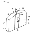
- a magnetic head shown in Figs. 1 and 2 is fundamentally different from the prior art magnetic head shown in Figs. 10 and 12 in that a pair of convex magnetic cores 11 and 12 have notches 13a and 14a which dig into side faces of magnetic films 19 and 20 in the range from the magnetic tape sliding face of the cores to a winding window 21 and are cut to an equal size in a direction perpendicular to the track width direction, and that the track width TW is regulated by the notches 13a and 14a.
- the pair of convex magnetic cores 11 and 12 which are opposed to each other through a magnetic gap 1 are bonded to each other by glass blocks 15 and 16.
- the convex magnetic cores 11 and 12 are mainly made of ferrite, and have the magnetic films 19 and 20 and the convex core bodies 17,18 .
- the magnetic films 19,20 have a high saturation magnetic flux density and cover the respective projection end faces of the convex core bodies 17 and 18 and both the side faces elongating therefrom.
- the side faces of the magnetic films 19 and 20 are cut to an equal size in the track width direction by the notches 13a and 14a.
- the notches reach the winding groove 21 while maintaining the track width TW attained at the magnetic tape sliding face.
- the reference numerals 17a and 18a designate track grooves.
- the provision of the notches 13a and 14a eliminates the butting misalignment of the convex core bodies 17 and 18, and the influences of rounds of edges of the magnetic films 19 and 20.
- the track width TW depends on the distance between the notches 13a and 14a. Therefore, the track width TW can be regulated with high accuracy.
- the track width TW is constant over the range from the face to the winding groove 21, furthermore, the track width TW does not vary even when the head is abraded, so that a head of high reliability is supplied.
- a material of the magnetic films 19 and 20 useful is a Sendust alloy material, a Co amorphous film, a Co superstructure nitriding alloy film, an Fe superstructure nitride film, an Fe nitride film, or the like. These materials may be disposed on the convex core bodies 17 and 18 by a suitable method such as vapor deposition, ion plating, or sputtering.
- the magnetic cores 11 and 12 are butted to each other through a gap member which is formed in the form of a film on at least one of the projection end faces of the cores.
- the gap member (which is not shown) may be made of a material such as SiO 2 , ZrO 2 , Ta 2 O 5 , glass, Cr, or a composite of these materials.
- the gap member When at least a part of the gap member is made of crystallized glass, the gap can be formed in a further satisfactory manner.
- the whole of the gap spacer may be made of crystallized glass.
- Crystallized glass is glass which, when it is again heated under special conditions after melting and shaping processes, is changed to an amorphous state and crystallized with preserving its original shape to have mechanical and thermal properties which are improved as compared with those of the original glass.
- the two magnetic cores 11 and 12 are firmly welded to each other. Therefore, the track width edges are prevented from being broken during the machining process, whereby the track width and the gap length can be formed stably.
- the crystallized glass after the crystallization has the yield point higher than that of the glass blocks 15 and 16.
- the gap portion is prevented from becoming loose in the process of forming the glass blocks 15 and 16, thereby allowing a gap to be formed in a further satisfactory manner.
- a pair of substrates made of, for example, Mn-Zn ferrite and having a surface which is formed by a lapping process or the like so as to have excellent parallelism and smoothness are prepared.
- parallel track grooves 17a and 18a for track regulation are formed by a grinding wheel or the like, thereby forming the pair of convex core bodies 17 and 18.
- At least one of the convex core bodies 17 and 18 is provided with the winding groove 21 through which coils can pass.
- the magnetic films 19 and 20 which have a high saturation magnetic flux density are formed by a vacuum thin film forming technique so as to cover one side face of each of the core bodies 17 and 18, thereby completing the pair of magnetic cores 11 and 12.
- a film-like gap member for forming the magnetic gap is disposed on one of the pair of magnetic cores 11 and 12.
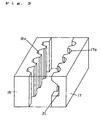
- the magnetic cores 11 and 12 are arranged so as to oppose to each other through the gap member as shown in Fig. 5.
- the gap member (which is not shown) may be made of a material such as SiO 2 , ZrO 2 , Ta 2 O 5 , glass, Cr, or a composite of these materials.
- a discharging electrode 25 is moved so as to approach the side portions of the pair of magnetic cores 11 and 12 in a butted state, to initiate a discharge, thereby forming notches 22.
- This allows the notches 22 to reach the winding groove 21 while maintaining the track width TW attained at the upper face.
- the butted state may be realized by supporting the cores by a jig, or by provisionally bonding the cores to each other by means of an adhesive.
- At least a part of the gap member, and the uppermost surface portions of the magnetic cores 11 and 12 are formed by crystallized glass.
- the cores in the butted state are heated in an electric oven or the like so that the glass melt.
- the crystallized glass becomes amorphous to be crystallized, and has mechanical and thermal properties which are improved as compared with those of the original glass, with the result that the cores can firmly be bonded to each other at the gap portion.
- a metal such as At or Ag may be used so that the cores are heated and pressed to be diffusion-bonded.
- conventional glass having a low melting point may be used so that heating adhesion is conducted.
- any method may be employed as far as it realizes means of making the gap faces contacted and bonded.
- the discharging electrode 25 is moved so as to approach the side portions of the pair of magnetic cores 11 and 12 which are in a bonded state at the gap portion, to initiate a discharge, thereby forming the notches 22.
- the surface roughness of the notches regulating the track width directly affects the track width accuracy. In order to attain the accuracy of ⁇ 0.5 ⁇ m, therefore, at least the surface roughness of 0.5 ⁇ m or less is required, and that of 0.2 ⁇ m or less is more preferable.
- the electric discharge machining is conducted in insulating oil.
- pure water having an electrical resistivity of 1 M ⁇ cm or higher may be used.
- a washing step in postprocesses may be omitted.
- the pair of magnetic cores 11 and 12 are then coupled to each other by the glass blocks 15 and 16.
- the glass blocks 15 and 16 are formed by a filling process under heat treatment.
- the substrates are sliced into chips as indicated by one-dot chain lines, and coils are wound on each chip.
- the magnetic films 19 and 20 are formed also on the side faces of the core bodies 17 and 18 in the vicinity of the magnetic gap 1 which are directed to the magnetic gap, thereby realizing a configuration in which the MIG head can satisfactorily exhibit its advantages that saturation at the gap faces during a recording process is suppressed and that the recording ability is excellent.
- the desired objects can be attained by conducting a discharge machining process only on a small portion of the magnetic films. In this case, the machining accuracy and speed are further improved.
- the notches 22 are formed by a discharge machining process.
- the notches 22 may be formed by a laser induced etching process.
- the pair of magnetic cores 11 and 12 in the butted state are irradiated from an upper side with an Ar laser beam 30 (having a spot diameter of 2 &Lm).
- the pair of magnetic cores 11 and 12 are immersed in a hydroxide of an alkali metal (for example, KOH), and therefore only a portion irradiated with the laser beam is machined by means of a thermal reaction.
- an alkali metal for example, KOH
- the width Cw of the notches 22 in the longitudinal direction of the track is set to be 30 ⁇ m or less.
- the detail is shown in Fig. 2 (notches are designated by 13a and 14a).
- the area to be machined can be reduced so that the machining speed is improved.
- the machining of a notch of a width of 10 ⁇ m required a period of 10 sec.
- the width Cw in the longitudinal direction of the track is 30 ⁇ m
- the machining of both the notches 13a and 14a requires 60 sec. in total. This machining speed is equal to that for the track grooves 17a and 18a, and seemed as an upper limit for a mass production.
- the machining accuracy is improved (when the film thickness is not greater than the spot diameter of the laser beam, the irradiation region becomes greater than the films so as to make the energy distribution nonuniform, thereby lowering the machining accuracy).
- the laser induced etching process is disclosed in Japanese laid open patent publication No. HEI2-276,009.
- the patent of the publication is directed to a process of machining a core block which is molded by glass, and is not related to a process of machining provisionally joined cores which have not yet been molded by glass as the case of the invention.
- the approximate track regulating process is conducted by a grinding process before the laser induced etching process.
- the pair of magnetic cores 11 and 12 are coupled to each other by the glass blocks 15 and 16.
- the glass blocks 15 and 16 are formed by a filling process under heat treatment.
- the substrates are sliced into chips as indicated by one-dot chain lines, and coils are wound on each chip.
- the invention is particularly effective in a narrow-gap and narrow-track MIG head.
- the invention can be applied also to a conventional ferrite head, and a head having a relatively large track width, and realizes an enhancement of the yield by means of improving the accuracy.
- the configuration in which the magnetic cores 11 and 12 are previously provided with the track grooves 17a and 18a as shown in Fig. 2 can reduce the machining amount of the notches 13a and 14a, and therefore is suitable for a mass production.
- Fig. 9 shows an embodiment of the magnetic recording/reproduction apparatus of the invention. While running, a magnetic tape 34 makes contact with a magnetic head 32 mounted on a rotary cylinder 33 which conducts a helical scanning, and a signal is recorded on and reproduced from the magnetic tape 34. According to the invention, a head of a narrow track and free from a track divergence is used, and therefore magnetic fluxes are not blurred at track edges such as side fringes so that a very large amount of information is recorded and reproduced.
- the material of the gap member can be non-crystallized glass .
Description
- The invention relates to a magnetic head as set forth in the preamble of
claim 1 and to a method of manufacturing a magnetic head as set forth in the preamble ofclaim 5. A magnetic head and a method of this kind are known from US-A-4 425 701. - The aforementioned document discloses a method in which by separate cutting or dicing steps two comb-like structures are formed from ferromagnetic substance core blocks, said dicing steps forming partial grooves which are separated from one other by a tooth or projection. After having filled the partial grooves with glass, mirror-grinded the blocks including the end faces of the projections and applied a gap spacer or film, the blocks are abutted to one another in a manner that opposing end faces of the projections of the opposing blocks match. After bonding the blocks to one another, the assembly thus formed is cut into the individual heads. There is no other grinding or cutting process which could influence the track width of the magnetic gap defined by the width of the projections.
- The accuracy of the track width of the magnetic gap is dependent of the accuracy with which the blocks are aligned. A mis-alignment influences the accuracy of the track width of all magnetic gaps. Further, the accuracy of the track width also depends of the accuracy of the width of the grooves. If those are unequal, it is not possible to attain an overall accuracy even if some of the track widths are accurately adjusted. All this is the result of the fact that an adjustment of the track width of the heads is not separately made.
- In a system such as a digital VTR wherein a large amount of signals are recorded and reproduced, it is essential to employ high density magnetic recording/reproduction techniques such as the narrow-track technique and the short-wavelength technique.
- Generally, it is known that high density recording/reproduction can be attained when the coercive force of a magnetic medium is increased and the saturation magnetic flux density (hereinafter referred to as "Bs") of a magnetic head is increased. Ferrit material which has mainly been used in the prior art as a magnetic head material has Bs of about 0.5 T. When a ferrite magnetic head is used for a metal tape having a coercive force as high as 80 kA/m or more, therefore, there occurs magnetic saturation so that recording cannot be conducted satisfactorily. To comply with this, researches have vigorously been conducted on magnetic heads using a material which has Bs larger than ferrite, such as a Sendust alloy material (Bs: about 1.0 T), a Co amorphous film (Bs: about 0.8 to 1.1 T), or a novel material such as a Co superstructure nitriding alloy film having Bs of 1.3 T or more, an Fe superstructure nitride film, or an Fe nitride film, particularly on a composite magnetic head or so-called MIG head in which the main core is made of ferrite and a magnetic thin film is disposed at least in the vicinity of the front gap.
- Fig. 10 shows the configuration of a MIG head. A pair of convex
magnetic cores magnetic gap 1 respectively compriseconvex core bodies flux density films magnetic cores glass blocks reference numeral 10 designates a winding hole through which coils can pass. - In such a magnetic head, as shown in Fig. 11 in detail, track dis-adjustments d1 and d2 are easily produced by production errors due to machining accuracy of track grooves 4a and 5a of the pair of
core bodies core bodies rounds magnetic films - In high density recording, these divergences and rounds of the edges tend to cause the properties to be impaired.
- As partly disclosed by U.S. Pat. No. 4,110,902, a method of regulating the track width by using a wire on a sliding face may be employed. In the method, however, the whole of the sliding face is machined so as to have a fixed track width, and the running of a magnetic medium causes a problem of abrasion resistance. Furthermore, magnetic properties are greatly impaired. According to the invention, a machining process is conducted only on the vicinity of a gap, and therefore the problem of abrasion resistance and the impairment of magnetic properties do not occur.
- U.S. Pat. No. 3,668,775 discloses a configuration in which the whole of a core constitutes the track width. Also in this configuration, magnetic properties are greatly impaired. Moreover, the chip has a reduced strength.
- U.S. Pat. No. 5,208,965 discloses a method in which a track width is regulated by track width regulation grooves. In the disclosed method, cores are separately machined, and then butted to be joined to each other, thereby producing butting errors. Therefore, the method cannot be employed in a production of a narrow-track width head.
- Recently, the track width and its accuracy are requested to be 10 µm or less and ±0.5 µm, respectively. As described above, however, it is substantially impossible according to the prior art to produce a magnetic head which fulfills the requirements while preventing the magnetic properties from being impaired.
- It is an object of the invention to provide a narrow-track magnetic head for high density recording and of high performance.
- It is another object of the invention to provide a method of producing a narrow-track magnetic head at an improved yield and a lower cost.
- It is a further object of the invention to provide a magnetic recording/reproduction apparatus which is suitable for a narrow track pitch.
- The above objects are attained by the process and apparatus defined in the appended claims.
- According to the process and the head configuration defined in the appended claims, a magnetic head which is suitable for a narrow track used in high density recording and free from a track divergence can be obtained at an improved yield and a lower cost. Since the track width is constant over a range from the face to the winding groove, furthermore, the track width does not vary even when the magnetic head is abraded, so that a head of high reliability is supplied.
- When the head is used, it is possible to provide a magnetic recording/reproduction apparatus which is suitable for a digital VTR.
-
- Fig. 1 is a perspective view of a magnetic head chip of an embodiment of the invention;
- Fig. 2 is a plan view of a part of the magnetic head chip of the embodiment of the invention;
- Fig. 3 is a perspective view illustrating a production method of an embodiment of the invention;
- Fig. 4 is a perspective view illustrating the production method of the embodiment of the invention;
- Fig. 5 is a perspective view illustrating the production method of the embodiment of the invention;
- Fig. 6 is a perspective view illustrating the production method of the embodiment of the invention;
- Fig. 7 is a perspective view illustrating the production method of the embodiment of the invention;
- Fig. 8 is a perspective view illustrating a production method of another embodiment of the invention;
- Fig. 9 is a perspective view illustrating a magnetic head and its vicinity of a magnetic recording apparatus of the invention;
- Fig. 10 is a perspective view of a prior art magnetic head chip; and
- Fig. 11 is a plan view of a part of the prior art magnetic head chip.
-
- Hereinafter, embodiments of the invention will be described with reference to the drawings.
- A magnetic head shown in Figs. 1 and 2 is fundamentally different from the prior art magnetic head shown in Figs. 10 and 12 in that a pair of convex
magnetic cores notches magnetic films winding window 21 and are cut to an equal size in a direction perpendicular to the track width direction, and that the track width TW is regulated by thenotches - In the magnetic head, the pair of convex
magnetic cores magnetic gap 1 are bonded to each other byglass blocks - The convex
magnetic cores magnetic films convex core bodies magnetic films convex core bodies magnetic films notches groove 21 while maintaining the track width TW attained at the magnetic tape sliding face. The reference numerals 17a and 18a designate track grooves. - The provision of the
notches convex core bodies magnetic films - The track width TW depends on the distance between the
notches - Since the track width TW is constant over the range from the face to the winding
groove 21, furthermore, the track width TW does not vary even when the head is abraded, so that a head of high reliability is supplied. - As a material of the
magnetic films convex core bodies - The
magnetic cores - When at least a part of the gap member is made of crystallized glass, the gap can be formed in a further satisfactory manner.
- The whole of the gap spacer may be made of crystallized glass.
- Crystallized glass is glass which, when it is again heated under special conditions after melting and shaping processes, is changed to an amorphous state and crystallized with preserving its original shape to have mechanical and thermal properties which are improved as compared with those of the original glass.
- Before the
notches magnetic cores - Preferably, the crystallized glass after the crystallization has the yield point higher than that of the glass blocks 15 and 16. When such glass is used, the gap portion is prevented from becoming loose in the process of forming the glass blocks 15 and 16, thereby allowing a gap to be formed in a further satisfactory manner.
- A method of producing the magnetic head will be described with reference to Figs. 3 to 8.
- First, a pair of substrates made of, for example, Mn-Zn ferrite and having a surface which is formed by a lapping process or the like so as to have excellent parallelism and smoothness are prepared. On the substrates, as shown in Fig. 3,
parallel track grooves 17a and 18a for track regulation are formed by a grinding wheel or the like, thereby forming the pair ofconvex core bodies convex core bodies groove 21 through which coils can pass. - As shown in Fig. 4, then, the
magnetic films core bodies magnetic cores - Next, a film-like gap member for forming the magnetic gap is disposed on one of the pair of
magnetic cores magnetic cores - As shown in Fig. 6, a discharging
electrode 25 is moved so as to approach the side portions of the pair ofmagnetic cores notches 22. This allows thenotches 22 to reach the windinggroove 21 while maintaining the track width TW attained at the upper face. The butted state may be realized by supporting the cores by a jig, or by provisionally bonding the cores to each other by means of an adhesive. - In order to further improve the gap accuracy, the following processes may be conducted.
- At least a part of the gap member, and the uppermost surface portions of the
magnetic cores - Then, the cores in the butted state are heated in an electric oven or the like so that the glass melt.
- The crystallized glass becomes amorphous to be crystallized, and has mechanical and thermal properties which are improved as compared with those of the original glass, with the result that the cores can firmly be bonded to each other at the gap portion.
- In place of crystallized glass, a metal such as At or Ag may be used so that the cores are heated and pressed to be diffusion-bonded. Alternatively, conventional glass having a low melting point may be used so that heating adhesion is conducted.
- In short, any method may be employed as far as it realizes means of making the gap faces contacted and bonded.
- As shown in Fig. 6, then, the discharging
electrode 25 is moved so as to approach the side portions of the pair ofmagnetic cores notches 22. - In the process of forming the
notches 22, since themagnetic cores - The surface roughness of the notches regulating the track width directly affects the track width accuracy. In order to attain the accuracy of ±0.5 µm, therefore, at least the surface roughness of 0.5 µm or less is required, and that of 0.2 µm or less is more preferable.
- In the case where the electric discharge machining was employed, when the single discharge energy was reduced to a level of 10-7 J, a surface roughness of 0.1 to 0.2 µm was attained in the process of machining an Fe-Ta-N film.
- Generally, the electric discharge machining is conducted in insulating oil. Alternatively, pure water having an electrical resistivity of 1 MΩ·cm or higher may be used. When such water is used, a washing step in postprocesses may be omitted.
- As shown in Fig. 7, the pair of
magnetic cores - Thereafter, the substrates are sliced into chips as indicated by one-dot chain lines, and coils are wound on each chip.
- According to the invention, the
magnetic films core bodies magnetic gap 1 which are directed to the magnetic gap, thereby realizing a configuration in which the MIG head can satisfactorily exhibit its advantages that saturation at the gap faces during a recording process is suppressed and that the recording ability is excellent. - When the butting of the convex cores is previously conducted at a certain higher accuracy, the desired objects can be attained by conducting a discharge machining process only on a small portion of the magnetic films. In this case, the machining accuracy and speed are further improved.
- In the embodiment described above, the
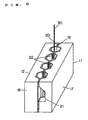
notches 22 are formed by a discharge machining process. Alternatively, thenotches 22 may be formed by a laser induced etching process. In this alternative, as shown in Fig. 8, the pair ofmagnetic cores magnetic cores - Preferably, the width Cw of the
notches 22 in the longitudinal direction of the track is set to be 30 µm or less. The detail is shown in Fig. 2 (notches are designated by 13a and 14a). According to this configuration, the area to be machined can be reduced so that the machining speed is improved. In the invention, the machining of a notch of a width of 10 µm required a period of 10 sec. In this case, when the width Cw in the longitudinal direction of the track is 30 µm, the machining of both thenotches track grooves 17a and 18a, and seemed as an upper limit for a mass production. - When the portions of the
magnetic films notches 22 have a thickness of 3 µm or more, the machining accuracy is improved (when the film thickness is not greater than the spot diameter of the laser beam, the irradiation region becomes greater than the films so as to make the energy distribution nonuniform, thereby lowering the machining accuracy). - The laser induced etching process is disclosed in Japanese laid open patent publication No. HEI2-276,009. The patent of the publication is directed to a process of machining a core block which is molded by glass, and is not related to a process of machining provisionally joined cores which have not yet been molded by glass as the case of the invention. In the invention, the approximate track regulating process is conducted by a grinding process before the laser induced etching process.
- As shown in Fig. 7, then, the pair of
magnetic cores - Thereafter, the substrates are sliced into chips as indicated by one-dot chain lines, and coils are wound on each chip.
- As described above, the invention is particularly effective in a narrow-gap and narrow-track MIG head. The invention can be applied also to a conventional ferrite head, and a head having a relatively large track width, and realizes an enhancement of the yield by means of improving the accuracy.
- The configuration in which the
magnetic cores track grooves 17a and 18a as shown in Fig. 2 can reduce the machining amount of thenotches - Even when the track width Tw is small, furthermore, the configuration in which the
track grooves 17a and 18a are respectively machined allows the core width Kw (Fig.2)to be large, so that a head which is excellent in chip strength and interface is provided. - Fig. 9 shows an embodiment of the magnetic recording/reproduction apparatus of the invention. While running, a
magnetic tape 34 makes contact with amagnetic head 32 mounted on arotary cylinder 33 which conducts a helical scanning, and a signal is recorded on and reproduced from themagnetic tape 34. According to the invention, a head of a narrow track and free from a track divergence is used, and therefore magnetic fluxes are not blurred at track edges such as side fringes so that a very large amount of information is recorded and reproduced. - Meawhile the material of the gap member can be non-crystallized glass .
Claims (10)
- A magnetic head comprising:characterized in thata pair of magnetic cores (11, 12) each of which has a convex shape part (17, 18), said convex shape parts (17, 18) being opposed to each other through a magnetic gap member (1);a pair of glass blocks (15, 16) which are disposed at both sides of said magnetic cores (11, 12) to couple said magnetic cores (11, 12) to each other; andnotches (13a, 14a) are formed at both sides of a magnetic tape sliding face constituted by upper faces of said convex shape parts (17, 18) of said magnetic cores (11, 12) to regulate a track width (TW), and said notches (13a, 14a) respectively reaching a winding groove (21) while maintaining the track width (TW),said magnetic cores (11, 12) each are made of a composite of a core body (17, 18) mainly made of a ferrite and a metal magnetic film (19, 20), andsaid notches (13a, 14a) are formed only in the metal magnetic film (19, 20) after coupling said magnetic cores (11, 12) to each other.
- A magnetic head according to claim 1, whereina width of said notches (13a, 14a) in a longitudinal direction of the track is 30 µm or less.
- A magnetic head according to one of claims 1 and 2, whereinat least a part of said magnetic gap member (1) is formed by crystallized glass.
- A method of manufacturing a magnetic head composed of a pair of magnetic cores each of which has a convex shape part, said convex shape parts being opposed to each other through a magnetic gap member, a pair of glass blocks which are disposed at both sides of said magnetic cores to couple said magnetic cores to each other, and notches formed at both sides of a magnetic tape sliding face constituted by upper faces of said convex shape parts of said magnetic cores to define a track width, said notches respectively reaching a winding groove while maintaining the track width, characterised in that after butting projection end faces of said magnetic cores through the magnetic gap member said notches are formed by an electric discharge machining process or by a laser induced etching process, to regulate the track width, and subsequent thereto glass is filled under heat treatment into said grooves and said notches at both sides of said magnetic cores.
- A method as set forth in claim 4 wherein said projection and faces are bonded to each other under the butted state by using at least a part of said magnetic gap member, before said notches are formed.
- A method of manufacturing a magnetic head according to claim 4 or 5, whereinsaid convex magnetic cores are made of a composite of a core body mainly made of a ferrite and a metal magnetic film, and said notches are formed only in said metal magnetic films.
- A method of manufacturing a magnetic head according to one of claims 4 to 6, wherein,in said process of forming notches which reach the winding groove by the electric discharge machining process, an insulation solvent for the electric discharge machining is water having an electrical resistivity of 1 MΩ·cm or higher.
- A method of manufacturing a magnetic head according to one of claims 5 and 6, wherein,in said process of forming notches which reach the winding groove by the laser induced etching process, portions of metal magnetic films for forming said notches have a thickness of 3 µm or more.
- A magnetic recording/reproduction apparatus comprising a magnetic head according to one of claims 1 to 3.
- A magnetic recording/reproduction apparatus comprising a magnetic head which is produced by a manufacturing method according to one of claims 4 to 8.
Applications Claiming Priority (9)
| Application Number | Priority Date | Filing Date | Title |
|---|---|---|---|
| JP247901/93 | 1993-10-04 | ||
| JP24790193 | 1993-10-04 | ||
| JP24790193 | 1993-10-04 | ||
| JP307845/93 | 1993-12-08 | ||
| JP30784593 | 1993-12-08 | ||
| JP30784593 | 1993-12-08 | ||
| JP6235705A JP2933491B2 (en) | 1993-10-04 | 1994-09-29 | Manufacturing method of magnetic head |
| JP23570594 | 1994-09-29 | ||
| JP235705/94 | 1994-09-29 |
Publications (3)
| Publication Number | Publication Date |
|---|---|
| EP0646907A2 EP0646907A2 (en) | 1995-04-05 |
| EP0646907A3 EP0646907A3 (en) | 1996-10-09 |
| EP0646907B1 true EP0646907B1 (en) | 1999-12-01 |
Family
ID=27332297
Family Applications (1)
| Application Number | Title | Priority Date | Filing Date |
|---|---|---|---|
| EP94115437A Expired - Lifetime EP0646907B1 (en) | 1993-10-04 | 1994-09-30 | Magnetic head and producing method of the same |
Country Status (4)
| Country | Link |
|---|---|
| US (2) | US5761789A (en) |
| EP (1) | EP0646907B1 (en) |
| JP (1) | JP2933491B2 (en) |
| DE (1) | DE69421882T2 (en) |
Families Citing this family (6)
| Publication number | Priority date | Publication date | Assignee | Title |
|---|---|---|---|---|
| JPH0830909A (en) * | 1994-07-15 | 1996-02-02 | Sony Corp | Magnetic head |
| DE69614759T2 (en) * | 1995-05-18 | 2002-06-27 | Matsushita Electric Ind Co Ltd | Magnetic head, manufacturing method therefor, and magnetic recording / reproducing apparatus using the same |
| US6631050B1 (en) | 1999-07-02 | 2003-10-07 | Matsushita Electric Industrial Co., Ltd. | Sealing glass for magnetic head and magnetic head using the same |
| JP2001283411A (en) * | 2000-03-30 | 2001-10-12 | Toshiba Corp | Magnetic head and its manufacturing method |
| KR100484059B1 (en) * | 2000-05-11 | 2005-04-18 | 마쯔시다덴기산교 가부시키가이샤 | Glass composition, sealing glass for magnetic head and magnetic head |
| WO2003010759A1 (en) * | 2001-07-23 | 2003-02-06 | Sony Corporation | Magnetic head |
Family Cites Families (24)
| Publication number | Priority date | Publication date | Assignee | Title |
|---|---|---|---|---|
| JPS4826527B1 (en) * | 1969-02-13 | 1973-08-11 | ||
| US4110902A (en) * | 1975-12-22 | 1978-09-05 | Hitachi, Ltd. | Method for manufacturing a magnetic head for video signal |
| US4425701A (en) * | 1980-10-17 | 1984-01-17 | Matsushita Electric Industrial Co., Ltd. | Methods of making magnetic recording heads |
| JPS5897124A (en) * | 1981-12-04 | 1983-06-09 | Matsushita Electric Ind Co Ltd | Manufacture for magnetic head |
| JPS59223924A (en) * | 1983-06-03 | 1984-12-15 | Mitsubishi Electric Corp | Production for magnetic head of narrow track width |
| JPS61126614A (en) * | 1984-11-21 | 1986-06-14 | Victor Co Of Japan Ltd | Magnetic head and its production |
| JPH0664705B2 (en) * | 1984-11-20 | 1994-08-22 | 松下電器産業株式会社 | Processing method of magnetic recording head |
| JPS61260408A (en) * | 1985-05-14 | 1986-11-18 | Matsushita Electric Ind Co Ltd | Track working method for magnetic head |
| US4751779A (en) * | 1986-04-02 | 1988-06-21 | Ds Scanner Co., Ltd. | Method of producing a core for magnetic head |
| JPS6370912A (en) * | 1986-09-12 | 1988-03-31 | Hitachi Ltd | Glass for joining magnetic head gap |
| CA1328506C (en) * | 1988-02-09 | 1994-04-12 | Kousou Ishihara | Magnetic head and method of manufacturing the same |
| JPH0727611B2 (en) * | 1988-03-09 | 1995-03-29 | 日本碍子株式会社 | Method for manufacturing core for magnetic head |
| JPH01276412A (en) * | 1988-04-26 | 1989-11-07 | Seiko Epson Corp | Manufacture for floating type magnetic head |
| US5170301A (en) * | 1988-08-03 | 1992-12-08 | Matsushita Electric Industrial Co., Ltd. | Magnetic head having core parts joined by low-melting point crystallized glass with composite gap |
| JPH0719347B2 (en) * | 1988-09-24 | 1995-03-06 | 日本碍子株式会社 | Manufacturing method of core slider for fixed magnetic disk drive |
| US5208965A (en) * | 1989-01-17 | 1993-05-11 | Victor Company Of Japan, Ltd. | Method for producing magnetic head having track regulation grooves formed at tape sliding surface |
| JPH0743813B2 (en) * | 1989-04-18 | 1995-05-15 | 日本碍子株式会社 | Method for manufacturing core for magnetic head |
| NL9100192A (en) * | 1991-02-04 | 1992-09-01 | Philips Nv | MAGNETIC HEAD. |
| JPH04305805A (en) * | 1991-04-02 | 1992-10-28 | Matsushita Electric Ind Co Ltd | Magnetic head |
| JPH04353607A (en) * | 1991-05-31 | 1992-12-08 | Matsushita Electric Ind Co Ltd | Magnetic head and manufacture thereof |
| JPH05143919A (en) * | 1991-11-01 | 1993-06-11 | Alps Electric Co Ltd | Magnetic head and production thereof |
| JPH06150243A (en) * | 1992-10-30 | 1994-05-31 | Mitsumi Electric Co Ltd | Production of head chip of magnetic head and head chip |
| JPH06208705A (en) * | 1993-01-11 | 1994-07-26 | Nec Kansai Ltd | Magnetic head and manufacture thereof |
| JPH06295412A (en) * | 1993-04-09 | 1994-10-21 | Matsushita Electric Ind Co Ltd | Magnetic head and production of magnetic head |
-
1994
- 1994-09-29 JP JP6235705A patent/JP2933491B2/en not_active Expired - Fee Related
- 1994-09-30 EP EP94115437A patent/EP0646907B1/en not_active Expired - Lifetime
- 1994-09-30 DE DE69421882T patent/DE69421882T2/en not_active Expired - Fee Related
-
1995
- 1995-06-05 US US08/461,964 patent/US5761789A/en not_active Expired - Fee Related
-
1997
- 1997-07-16 US US08/895,205 patent/US5905612A/en not_active Expired - Fee Related
Also Published As
| Publication number | Publication date |
|---|---|
| EP0646907A2 (en) | 1995-04-05 |
| JPH07220218A (en) | 1995-08-18 |
| US5905612A (en) | 1999-05-18 |
| DE69421882T2 (en) | 2000-04-20 |
| JP2933491B2 (en) | 1999-08-16 |
| US5761789A (en) | 1998-06-09 |
| EP0646907A3 (en) | 1996-10-09 |
| DE69421882D1 (en) | 2000-01-05 |
Similar Documents
| Publication | Publication Date | Title |
|---|---|---|
| JPH0719347B2 (en) | Manufacturing method of core slider for fixed magnetic disk drive | |
| KR0126289B1 (en) | Magnetic head and method of manufacturing the same | |
| EP0646907B1 (en) | Magnetic head and producing method of the same | |
| KR100320709B1 (en) | Magnetic head | |
| US4926276A (en) | Magnetic head having reinforcing block | |
| US5043842A (en) | Magnetic head core with special gap structure | |
| US5924189A (en) | Method for producing a magnetic head | |
| KR100385126B1 (en) | Magnetic head | |
| JPH0778853B2 (en) | Floating type magnetic head and manufacturing method thereof | |
| JPH10293904A (en) | Magnetic head and magnetic recording and reproducing device | |
| EP0242861B1 (en) | Magnetic head | |
| JP3104185B2 (en) | Magnetic head | |
| JP2508522B2 (en) | Manufacturing method of composite magnetic head | |
| JP2000020908A (en) | Magnetic head, its manufacture, and magnetic recording and reproducing device | |
| GB2291532A (en) | A method of producing a metal-in-gap magnetic head | |
| JP2551582B2 (en) | Thin film magnetic head | |
| JPH0241083B2 (en) | KINZOKUJISEIHAKUMAKUGATAJIKIHETSUDONOSEIZOHOHO | |
| JPH0935209A (en) | Magnetic head and its manufacture and magnetic recording and reproducing device using the them | |
| JPH1153709A (en) | Magnetic head, its manufacture and magnetic recording and reproducing device using the same | |
| JPH06243416A (en) | Magnetic head and its production | |
| JPS63241709A (en) | Manufacture of magnetic head | |
| JPH0520636A (en) | Thin-film magnetic head | |
| JPH0561681B2 (en) | ||
| JPH01258206A (en) | Magnetic head and its manufacture | |
| JPH05334615A (en) | Magnetic head and its production |
Legal Events
| Date | Code | Title | Description |
|---|---|---|---|
| PUAI | Public reference made under article 153(3) epc to a published international application that has entered the european phase |
Free format text: ORIGINAL CODE: 0009012 |
|
| AK | Designated contracting states |
Kind code of ref document: A2 Designated state(s): DE FR GB NL |
|
| PUAL | Search report despatched |
Free format text: ORIGINAL CODE: 0009013 |
|
| AK | Designated contracting states |
Kind code of ref document: A3 Designated state(s): DE FR GB NL |
|
| 17P | Request for examination filed |
Effective date: 19961129 |
|
| 17Q | First examination report despatched |
Effective date: 19980526 |
|
| GRAG | Despatch of communication of intention to grant |
Free format text: ORIGINAL CODE: EPIDOS AGRA |
|
| GRAG | Despatch of communication of intention to grant |
Free format text: ORIGINAL CODE: EPIDOS AGRA |
|
| GRAG | Despatch of communication of intention to grant |
Free format text: ORIGINAL CODE: EPIDOS AGRA |
|
| GRAH | Despatch of communication of intention to grant a patent |
Free format text: ORIGINAL CODE: EPIDOS IGRA |
|
| GRAH | Despatch of communication of intention to grant a patent |
Free format text: ORIGINAL CODE: EPIDOS IGRA |
|
| GRAA | (expected) grant |
Free format text: ORIGINAL CODE: 0009210 |
|
| AK | Designated contracting states |
Kind code of ref document: B1 Designated state(s): DE FR GB NL |
|
| REF | Corresponds to: |
Ref document number: 69421882 Country of ref document: DE Date of ref document: 20000105 |
|
| ET | Fr: translation filed | ||
| PLBE | No opposition filed within time limit |
Free format text: ORIGINAL CODE: 0009261 |
|
| STAA | Information on the status of an ep patent application or granted ep patent |
Free format text: STATUS: NO OPPOSITION FILED WITHIN TIME LIMIT |
|
| 26N | No opposition filed | ||
| REG | Reference to a national code |
Ref country code: GB Ref legal event code: IF02 |
|
| PGFP | Annual fee paid to national office [announced via postgrant information from national office to epo] |
Ref country code: FR Payment date: 20050823 Year of fee payment: 12 |
|
| PGFP | Annual fee paid to national office [announced via postgrant information from national office to epo] |
Ref country code: NL Payment date: 20050915 Year of fee payment: 12 |
|
| PGFP | Annual fee paid to national office [announced via postgrant information from national office to epo] |
Ref country code: DE Payment date: 20050922 Year of fee payment: 12 |
|
| PGFP | Annual fee paid to national office [announced via postgrant information from national office to epo] |
Ref country code: GB Payment date: 20050928 Year of fee payment: 12 |
|
| PG25 | Lapsed in a contracting state [announced via postgrant information from national office to epo] |
Ref country code: NL Free format text: LAPSE BECAUSE OF NON-PAYMENT OF DUE FEES Effective date: 20070401 |
|
| PG25 | Lapsed in a contracting state [announced via postgrant information from national office to epo] |
Ref country code: DE Free format text: LAPSE BECAUSE OF NON-PAYMENT OF DUE FEES Effective date: 20070403 |
|
| GBPC | Gb: european patent ceased through non-payment of renewal fee |
Effective date: 20060930 |
|
| NLV4 | Nl: lapsed or anulled due to non-payment of the annual fee |
Effective date: 20070401 |
|
| REG | Reference to a national code |
Ref country code: FR Ref legal event code: ST Effective date: 20070531 |
|
| PG25 | Lapsed in a contracting state [announced via postgrant information from national office to epo] |
Ref country code: GB Free format text: LAPSE BECAUSE OF NON-PAYMENT OF DUE FEES Effective date: 20060930 |
|
| PG25 | Lapsed in a contracting state [announced via postgrant information from national office to epo] |
Ref country code: FR Free format text: LAPSE BECAUSE OF NON-PAYMENT OF DUE FEES Effective date: 20061002 |