EP0646761B1 - System for mounting a gun barrel of a medium or large caliber weapon - Google Patents
System for mounting a gun barrel of a medium or large caliber weapon Download PDFInfo
- Publication number
- EP0646761B1 EP0646761B1 EP94401875A EP94401875A EP0646761B1 EP 0646761 B1 EP0646761 B1 EP 0646761B1 EP 94401875 A EP94401875 A EP 94401875A EP 94401875 A EP94401875 A EP 94401875A EP 0646761 B1 EP0646761 B1 EP 0646761B1
- Authority
- EP
- European Patent Office
- Prior art keywords
- sleeve
- nut
- worm
- plunger
- pinion
- Prior art date
- Legal status (The legal status is an assumption and is not a legal conclusion. Google has not performed a legal analysis and makes no representation as to the accuracy of the status listed.)
- Expired - Lifetime
Links
Images

Classifications
-
- F—MECHANICAL ENGINEERING; LIGHTING; HEATING; WEAPONS; BLASTING
- F41—WEAPONS
- F41A—FUNCTIONAL FEATURES OR DETAILS COMMON TO BOTH SMALLARMS AND ORDNANCE, e.g. CANNONS; MOUNTINGS FOR SMALLARMS OR ORDNANCE
- F41A21/00—Barrels; Gun tubes; Muzzle attachments; Barrel mounting means
- F41A21/48—Barrel mounting means, e.g. releasable mountings for replaceable barrels
- F41A21/482—Barrel mounting means, e.g. releasable mountings for replaceable barrels using continuous threads on the barrel
Definitions
- the present invention relates to a system for mounting the barrel of a medium or large caliber weapon on a sleeve of the breech assembly of the weapon, said system being of the type comprising a nut intended to be screwed on a threaded end of the tube.
- the attachment of the tube to the sleeve is generally carried out according to two techniques mounting.
- a first technique the tube is screwed into the sleeve by means of threads complementary provided respectively in the sleeve and on the tube.
- this mounting technique requires rotating the tube, which is not a simple operation taking into account the dimensions and heaviness of the tube.
- thread starters which must be machined very precisely, which is also a delicate operation to carry out.
- the tube is fixed to the sleeve at by means of a nut located at the front of the sleeve and the thread engages with a thread provided on the muff.
- a nut located at the front of the sleeve and the thread engages with a thread provided on the muff.
- the main object of the invention is to alleviate the disadvantages of the first mounting technique above by perfecting the second technique of above-mentioned assembly based on the use of a nut, but the position of the nut and its control system in rotation are modified to facilitate the operations of assembly while limiting machining operations to make on the tube and on the sleeve.
- the invention proposes, according to the description of document US-A-3,611,611, a system of mounting of the tube of the aforementioned type and which is characterized by that the nut is freely mounted by an opening inside a housing of the sleeve for receiving said threaded end of the tube once it is inserted inside the sleeve, and in that said system also includes a drive device in rotation of the nut which consists of a device gears and a control means actuated from the outside of the sleeve and intended to engage with the gear device.
- the gear device comprises a pinion which meshes a straight toothing provided on the peripheral surface of the nut.
- the pinion is integral with a shaft, one end of which less protrudes outside the sleeve, the means of control actuated from outside the sleeve being constituted by a tool, such as a key, intended to come engaged with said shaft to drive it in rotation.
- the pinion of the assembly can be generally located outside the sleeve, a light being provided in the latter at the level of the housing containing the nut to allow the pinion to mesh with the external teeth of the nut.
- the nut of the mounting can be advantageously introduced inside of the sleeve through one of the lateral openings thereof, these openings being necessary to allow the room to rotate.
- the pinion of the gear device cooperates with a pinion locking device in the opposite direction of rotation to that corresponding to screwing the nut onto the tube, this device being disengageable to allow the disassembly operation of the tube.
- this blocking device consists of a pivoting pawl intended to engage between the teeth of the pinion under the action of a spring retractable reminder by means of a lever.
- the pinion control axis of the gear unit is accessible from the front or from the back of the sleeve, which has an advantage, especially in the case of mounting a tube on a tank turret.
- the gear device comprises a screw endless which engages a helical toothing provided on the peripheral surface of the nut.
- the worm is hollow and mounted in a housing machined in the thickness of the sleeve
- the control means actuated from outside the sleeve consists of a tool such as a key intended to be partially engaged inside the worm for drive it in rotation, the housing containing the screw opening into the housing containing the nut for allow the screw to mesh with the nut.
- the system also includes a locking device for rotation of the worm screw while that the control means is not engaged inside of said screw.
- this device lock includes a plunger housed in the bottom of the screw and axially movable between two positions, a pin retractable locking radial and a return spring which tends to automatically bring the diver back into one said positions or blocking position, said pin radial being intended either to engage in a notch of the sleeve to immobilize the worm in rotation when the plunger is in its locked position, either to be retracted inside a notch provided in the body of the diver when the latter is in the other of said positions to allow rotation of the screw unending.
- the means of control must be engaged in the auger so to lean on the diver to unlock the counter locking and thus allow rotation of the screw without end.
- the tightening torque necessary for the tightening of the nut can be notably reduced due to the reduction ratio which is obtained by the use of a gear device.
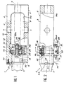
- a medium or large caliber weapon 1 includes in particular a cylinder head assembly 2 equipped with a sleeve 3 on which comes to mount the tube 5 of the weapon, like this is schematically shown in Figure 1.
- the sleeve 3 has two opposite openings respectively front 6 and rear 7 at its two extremities. Between these two openings 6 and 7, the volume inside of sleeve 3 is divided into front housing 8 adjacent to the front opening 6, and a rear housing 9 adjacent to the rear opening 7.
- a loading chamber C of the pivoting type for example, is mounted in the rear housing 9 of the sleeve 3, the pivot axis X-X of this chamber C being for example perpendicular to the axis of swiveling of the weapon.
- the tube 5 is fixed to the sleeve 3 by means of a nut 10 intended to cooperate with a threaded end 12 of the tube 5.
- the nut 10 is freely mounted in the front housing 8 of the sleeve 3.
- the connection of the tube 5 on the sleeve 3 is effected by rotation of the nut 10 on the threaded end 12 of the tube 5 by means of a mounting system which includes a device for gears 13 and a control means 15 ( Figure 2) actuated from outside the sleeve 3 and intended for engage the gear device 13 to cause the nut 10 to rotate.
- the gear device 13 includes a pinion 17 which meshes a straight toothing 19 cut on the peripheral surface of the nut 10.
- the pinion 17 is integral in rotation with a shaft 20 which cross right through. Tree 20 ends, each time end, by a head 20a of hexagonal shape by example.
- the sleeve 3 comprises a side opening 22 through which the nut 10 is introduced into the housing 8 of the sleeve 3.
- the pinion 17 is partially housed in this opening 22 for engaging the external toothing 19 of the nut 10 and so that the shaft 20 secured to the pinion 17 remains outside the sleeve 3 to be able to freely access each end of the tree.
- the shaft 20 is supported in rotation by a cover 24 attached to the opening 22 of the sleeve 3 and fixed to it the latter by any appropriate means.
- the mounting system is completed by a locking device 25 which cooperates with the pinion 17 to lock it in the opposite direction of rotation that corresponding to the tightening of the nut 10 on the threaded end 12 of the tube 5, and to brake the rotation of the pinion 17 in the other direction.
- the locking device 25 comprises a pivoting pawl 26 intended to engage between the teeth pinion 17 under the action of a return spring 28.
- the ratchet 26 is retractable by means of a lever 29 which protrudes outside the cover 24 through an opening 24a.
- the nut 10 is mounted freely inside of the front housing 8 of the sleeve 3 through the opening 22, and the threaded rear part 12 of the tube 5 is engaged by the front opening 6 of the sleeve 3 to center the nut 10 on the tube 5.
- the cover 24 fitted with the pinion 17 and of the locking device 25 is attached to the opening 22 of the sleeve 3, so as to engage the teeth of the pinion 17 with the external teeth 19 of the nut 10.
- the control means 15 which is, for example, a tool such as a key engaged with the head 20a of one of the ends of the shaft 20, it causes the rotation of the pinion 17 which causes its turn the rotation of the nut 10 and an axial displacement of the tube 5.
- tube 5 The assembly operation of tube 5 is finished when an external radial shoulder 30 of the tube 5 comes into abutment against the front end face of the sleeve 3, and that the nut 10 comes to bear against the bottom of the housing before 8.
- two notches 31 and 32 respectively provided at the shoulder 30 of the tube 5 and of the front face of the sleeve 3, are located opposite each other.
- a key 33 is then engaged in the defined space by these two notches 31 and 32, and fixed to the sleeve 3 at by means of a screw 35 for example.
- Pinion 17 of the first embodiment is replaced by a freely mounted worm 40 in a housing machined in the thickness 41 of the sleeve 3.
- This housing 41 extends perpendicular to the axis of the sleeve 3 and opens laterally, towards its end, in the front housing 8 of the sleeve 3 so that the screw endless 40 could engage the external toothing 19 of the nut 10.
- This toothing 19 is in this case a helical teeth.
- the worm 40 is hollow so that ability to introduce control means 15 therein by a tool such as a hexagon wrench by example, to rotate the worm 40, the profile of the internal housing 42 of the worm 40 being complementary to that of the tool.
- the worm 40 is retained axially at the interior of the housing 41 of the sleeve 3 by a ring threaded 43 which screws into the housing 41.
- the ring 43 has an internal diameter sufficient to allow the passage of the control means 15.
- the mounting system is also completed by a locking device 25 which cooperates with the screw endless 40 to lock it in rotation as long as the means 15 is not engaged in the housing internal 42 of the worm gear 40, as will be explained below.
- the locking device 25 comprises a plunger 45 mounted in the internal housing 42 which crosses axially and right through the worm 40.
- the plunger 45 has at one end a head 46 which is extended by a body 47 having a groove annular device 48 intended to cooperate with a retractable blocking pin 50.
- the pawn of blocking 50 is intended to cooperate with at least one hole radial 52 which passes through the endless screw 40 and which extends into the sleeve 3.
- the pin 50 has a head 53 extended by a body 54 whose free end is round shape. Pawn 50 is inserted from the inside of the screw 40 so that its body 54 engages in the hole 52 to immobilize in rotation the screw without end 40 relative to the sleeve 3.
- a return spring 55 is mounted around the body 47 of the plunger 45 and the assembly is introduced freely in the internal housing 42 of the worm 40.
- the return spring 55 is intended to bear on the one hand, against the head 46 of the plunger 45 and, on the other hand hand, against an annular shoulder 56 formed at the interior of the internal housing 42 of the worm 40.
- the plunger 45 is engaged inside the screw without end 40 until the end of its body 47 is protrusion beyond the bottom end of the housing 42 which leads to the outside.
- a pin 58 is then engaged through the body 47 of the plunger 45 and is supported against the end of the worm 40.
- the plunger 45 under the action of the return spring 55 is then in a first position or blocking position. In this position, the head 53 of the retractable pin 50 is supported against the body 47 of the plunger 45, that is to say that the throat 48 of body 47 of plunger 45 is not facing of pawn 50.
- nut 10 is mounted freely inside of the front housing 8 of the sleeve 3, and the rear part threaded 12 of the tube 5 is engaged by the front opening 6 of the sleeve 3 to center the nut 10 on the tube.
- the control means 15 are introduced to the interior of the housing 42 of the worm 40 to exert sufficient pressure on the head 46 of diver 45 to move it in a second position where the pin 50 is opposite the groove 48 of the body 47 of the plunger 45.
- the pin 50 can partially retract to inside the groove 48 to disengage from the sleeve 3 and thus allow the screw to be released in rotation without end 40.
- the rotation of the screw 40 causes the rotation of the nut 10 and an axial displacement of the tube 5.
- the control means 15 is released from the auger 40.
- the plunger 45 automatically returns to its locking position under the action of the spring reminder 55.
- the displacement of the plunger 45 forces the pawn 50 to clear the throat 48 and to penetrate further into the hole 52 of the sleeve 3 to immobilize in rotation the worm gear 40.
- This second embodiment presents in particular the advantage of eliminating the cover 24 of the first embodiment, that is to say that the system of assembly is fully contained inside the sleeve 3.
- the sleeve 3 received a chamber C of the type swivel.
- the sleeve 3 has two side openings 9a facing each other (FIG. 1) for allow the pivoting of chamber C.
- the nut 10 is advantageously introduced into the sleeve 3 by one of the openings 9a.
- the lateral opening 22 initially planned to introduce the nut 10 can be reduced to a simple light 22a (figure 3) just necessary to allow the pinion 17 to mesh the nut 10.
- This variant offers in particular the advantage less weaken the sleeve 3.
Description
La présente invention concerne un système de montage du tube d'une arme de moyen ou gros calibre sur un manchon de l'ensemble culasse de l'arme, ledit système étant du type comprenant un écrou destiné à être vissé sur une extrémité filetée du tube.The present invention relates to a system for mounting the barrel of a medium or large caliber weapon on a sleeve of the breech assembly of the weapon, said system being of the type comprising a nut intended to be screwed on a threaded end of the tube.
A l'heure actuelle, la fixation du tube sur le manchon s'effectue généralement suivant deux techniques de montage. Selon une première technique, le tube est vissé dans le manchon au moyen de filetages complémentaires prévus respectivement dans le manchon et sur le tube. Concrètement, cette technique de montage nécessite de faire tourner le tube, ce qui n'est pas une opération simple compte tenu des dimensions et de la lourdeur du tube. En outre, dans le cas où l'on désire obtenir un positionnement angulaire déterminé entre tube et manchon, il faut prévoir des départs de filetage qui doivent être usinés d'une manière très précise, ce qui est également une opération délicate à réaliser. Selon une deuxième technique, le tube est fixé au manchon au moyen d'un écrou situé à l'avant du manchon et dont le filetage vient en prise avec un filetage prévu sur le manchon. Dans ce cas, il n'est plus nécessaire de faire tourner le tube, mais la présence de l'écrou à l'avant du manchon augmente l'encombrement de ce dernier. Cependant, le vissage de l'écrou reste encore une opération délicate à réaliser compte-tenu du couple de serrage qu'il faut appliquer.Currently, the attachment of the tube to the sleeve is generally carried out according to two techniques mounting. According to a first technique, the tube is screwed into the sleeve by means of threads complementary provided respectively in the sleeve and on the tube. Concretely, this mounting technique requires rotating the tube, which is not a simple operation taking into account the dimensions and heaviness of the tube. In addition, in the event that one desires obtain a determined angular positioning between tube and sleeve, it is necessary to provide thread starters which must be machined very precisely, which is also a delicate operation to carry out. According to a second technique, the tube is fixed to the sleeve at by means of a nut located at the front of the sleeve and the thread engages with a thread provided on the muff. In this case, it is no longer necessary to do turn the tube, but the presence of the nut on the front of the sleeve increases the size of the latter. However, tightening the nut is still a delicate operation to be carried out taking into account the required tightening torque apply.
Le but principal de l'invention est de pallier les inconvénients de la première technique de montage précitée en perfectionnant la seconde technique de montage précitée basée sur l'utilisation d'un écrou, mais la position de l'écrou et son système de commande en rotation sont modifiés pour faciliter les opérations de montage tout en limitant les opérations d'usinage à réaliser sur le tube et sur le manchon.The main object of the invention is to alleviate the disadvantages of the first mounting technique above by perfecting the second technique of above-mentioned assembly based on the use of a nut, but the position of the nut and its control system in rotation are modified to facilitate the operations of assembly while limiting machining operations to make on the tube and on the sleeve.
A cet effet, l'invention propose, suivant l'exposé du document US-A-3 611 611, un système de montage du tube du type précité et qui est caractérisé en ce que l'écrou est monté librement par une ouverture à l'intérieur d'un logement du manchon pour recevoir ladite extrémité filetée du tube une fois celle-ci introduite à l'intérieur du manchon, et en ce que ledit système comprend également un dispositif d'entraínement en rotation de l'écrou qui est constitué d'un dispositif à engrenages et d'un moyen de commande actionné depuis l'extérieur du manchon et destiné à venir en prise avec le dispositif à engrenages.To this end, the invention proposes, according to the description of document US-A-3,611,611, a system of mounting of the tube of the aforementioned type and which is characterized by that the nut is freely mounted by an opening inside a housing of the sleeve for receiving said threaded end of the tube once it is inserted inside the sleeve, and in that said system also includes a drive device in rotation of the nut which consists of a device gears and a control means actuated from the outside of the sleeve and intended to engage with the gear device.
Selon un premier mode de réalisation de l'invention, le dispositif à engrenages comprend un pignon qui engrène une denture droite prévue sur la surface périphérique de l'écrou.According to a first embodiment of the invention, the gear device comprises a pinion which meshes a straight toothing provided on the peripheral surface of the nut.
Selon ce premier mode de réalisation, le pignon est solidaire d'un arbre dont une extrémité au moins fait saillie à l'extérieur du manchon, le moyen de commande actionné depuis l'extérieur du manchon étant constitué par un outil, tel qu'une clé, destiné à venir en prise avec ledit arbre pour l'entraíner en rotation.According to this first embodiment, the pinion is integral with a shaft, one end of which less protrudes outside the sleeve, the means of control actuated from outside the sleeve being constituted by a tool, such as a key, intended to come engaged with said shaft to drive it in rotation.
Avantageusement, le pignon du système de montage peut être globalement situé à l'extérieur du manchon, une lumière étant prévue dans ce dernier au niveau du logement contenant l'écrou pour permettre au pignon d'engréner la denture externe de l'écrou.Advantageously, the pinion of the assembly can be generally located outside the sleeve, a light being provided in the latter at the level of the housing containing the nut to allow the pinion to mesh with the external teeth of the nut.
Dans le cas d'une arme où le manchon renferme une chambre du type pivotant, l'écrou du système de montage peut être avantageusement introduit à l'intérieur du manchon par l'une des ouvertures latérales de celui-ci, ces ouvertures étant nécessaires pour permettre à la chambre de pivoter.In the case of a weapon where the sleeve contains a pivoting type chamber, the nut of the mounting can be advantageously introduced inside of the sleeve through one of the lateral openings thereof, these openings being necessary to allow the room to rotate.
Selon une autre caractéristique de ce premier mode de réalisation, le pignon du dispositif à engrenages coopère avec un dispositif de blocage du pignon dans le sens de rotation inverse de celui correspondant au vissage de l'écrou sur le tube, ce dispositif étant débrayable pour permettre l'opération de démontage du tube.According to another characteristic of this first embodiment, the pinion of the gear device cooperates with a pinion locking device in the opposite direction of rotation to that corresponding to screwing the nut onto the tube, this device being disengageable to allow the disassembly operation of the tube.
A titre d'exemple, ce dispositif de blocage est constitué par un cliquet pivotant destiné à s'engager entre les dents du pignon sous l'action d'un ressort de rappel escamotable au moyen d'un levier.For example, this blocking device consists of a pivoting pawl intended to engage between the teeth of the pinion under the action of a spring retractable reminder by means of a lever.
Ainsi, l'axe de commande en rotation du pignon du dispositif à engrenages est accessible par l'avant ou par l'arrière du manchon, ce qui présente un avantage, notamment dans le cas du montage d'un tube sur une tourelle de char.Thus, the pinion control axis of the gear unit is accessible from the front or from the back of the sleeve, which has an advantage, especially in the case of mounting a tube on a tank turret.
Selon un second mode de réalisation de l'invention, le dispositif à engrenages comprend une vis sans fin qui engrène une denture hélicoidale prévue sur la surface périphérique de l'écrou.According to a second embodiment of the invention, the gear device comprises a screw endless which engages a helical toothing provided on the peripheral surface of the nut.
Selon une autre caractéristique de ce second mode de réalisation, la vis sans fin est creuse et montée dans un logement usiné dans l'épaisseur du manchon, et le moyen de commande actionné depuis l'extérieur du manchon est constitué par un outil tel qu'une clé destinée à être en partie engagée à l'intérieur de la vis sans fin pour entraíner celle-ci en rotation, le logement contenant la vis débouchant dans le logement contenant l'écrou pour permettre à la vis d'engréner l'écrou.According to another characteristic of this second embodiment, the worm is hollow and mounted in a housing machined in the thickness of the sleeve, and the control means actuated from outside the sleeve consists of a tool such as a key intended to be partially engaged inside the worm for drive it in rotation, the housing containing the screw opening into the housing containing the nut for allow the screw to mesh with the nut.
Selon une autre caractéristique de ce second mode de réalisation, le système comprend également un dispositif de blocage en rotation de la vis sans fin tant que le moyen de commande n'est pas engagé à l'intérieur de ladite vis.According to another characteristic of this second embodiment, the system also includes a locking device for rotation of the worm screw while that the control means is not engaged inside of said screw.
Selon un exemple de réalisation, ce dispositif de blocage comprend un plongeur logé dans le fond de la vis et mobile axialement entre deux positions, un pion radial de blocage escamotable et un ressort de rappel qui tend à ramener automatiquement le plongeur dans l'une desdites positions ou position de blocage, ledit pion radial étant destiné soit à s'engager dans une encoche du manchon pour immobiliser en rotation la vis sans fin lorsque le plongeur est dans sa position de blocage, soit à s'escamoter à l'intérieur d'une encoche prévue dans le corps du plongeur lorsque ce dernier est dans l'autre desdites positions pour permettre la rotation de la vis sans fin.According to an exemplary embodiment, this device lock includes a plunger housed in the bottom of the screw and axially movable between two positions, a pin retractable locking radial and a return spring which tends to automatically bring the diver back into one said positions or blocking position, said pin radial being intended either to engage in a notch of the sleeve to immobilize the worm in rotation when the plunger is in its locked position, either to be retracted inside a notch provided in the body of the diver when the latter is in the other of said positions to allow rotation of the screw unending.
Avec un tel dispositif de blocage, le moyen de commande doit être engagé dans la vis sans fin de manière à prendre appui sur le plongeur pour débloquer le pion de blocage et permettre ainsi la rotation de la vis sans fin.With such a locking device, the means of control must be engaged in the auger so to lean on the diver to unlock the counter locking and thus allow rotation of the screw without end.
D'une manière générale, selon un autre avantage important de l'invention, le couple de serrage nécessaire au vissage de l'écrou peut être notablement réduit du fait du rapport de réduction qui est obtenu par l'utilisation d'un dispositif à engrenages.Generally speaking, according to another important advantage of the invention, the tightening torque necessary for the tightening of the nut can be notably reduced due to the reduction ratio which is obtained by the use of a gear device.
D'autres avantages, caractéristiques et détails de l'invention ressortiront de la description explicative qui va suivre faite en référence aux dessins annexés, donnés uniquement à titre d'exemple et dans lesquels :
- la figure 1 est une vue en coupe axiale avec arrachement partiel d'un mode de réalisation du système de montage du tube d'une arme selon l'invention,
- la figure 2 est une vue de côté avec arrachement partiel, suivant la flèche II de la figure 1,
- la figure 3 est une vue en coupe suivant la ligne III-III de la figure 2,
- la figure 4 est une vue en coupe pour illustrer un second mode de réalisation d'un système de montage selon l'invention, et
- la figure 5 est une vue agrandie du détail indiqué par la flèche V sur la figure 4.
- FIG. 1 is a view in axial section with partial cutaway of an embodiment of the system for mounting the barrel of a weapon according to the invention,
- FIG. 2 is a side view with partial cutaway, according to arrow II in FIG. 1,
- FIG. 3 is a sectional view along line III-III of FIG. 2,
- FIG. 4 is a sectional view to illustrate a second embodiment of a mounting system according to the invention, and
- FIG. 5 is an enlarged view of the detail indicated by the arrow V in FIG. 4.
Une arme 1 de moyen ou gros calibre comprend
notamment un ensemble culasse 2 équipé d'un manchon 3 sur
lequel vient se monter le tube 5 de l'arme, comme cela
est schématiquement représenté à la figure 1.A medium or large caliber weapon 1 includes
in particular a
Le manchon 3 comporte deux ouvertures opposées
respectivement avant 6 et arrière 7 à ses deux
extrémités. Entre ces deux ouvertures 6 et 7, le volume
intérieur du manchon 3 est divisé en un logement avant 8
adjacent à l'ouverture avant 6, et un logement arrière 9
adjacent à l'ouverture arrière 7.The
Une chambre de chargement C, du type pivotant
par exemple, est montée dans le logement arrière 9 du
manchon 3, l'axe de pivotement X-X de cette chambre C
étant par exemple perpendiculaire à l'axe de
tourillonement de l'arme.A loading chamber C, of the pivoting type
for example, is mounted in the
Le tube 5 est fixé au manchon 3 au moyen d'un
écrou 10 destiné à coopérer avec une extrémité filetée 12
du tube 5. L'écrou 10 est monté librement dans le
logement avant 8 du manchon 3. Le raccordement du tube 5
sur le manchon 3 s'effectue par rotation de l'écrou 10
sur l'extrémité filetée 12 du tube 5 au moyen d'un
système de montage qui comprend un dispositif à
engrenages 13 et un moyen de commande 15 (figure 2)
actionné depuis l'extérieur du manchon 3 et destiné à
venir en prise avec le dispositif à engrenages 13 pour
provoquer la rotation de l'écrou 10.The
Selon un premier mode de réalisation illustré
sur les figures 1 à 3, le dispositif à engrenages 13
comprend un pignon 17 qui engrène une denture droite 19
taillée sur la surface périphérique de l'écrou 10. Le
pignon 17 est solidaire en rotation d'un arbre 20 qui le
traverse de part en part. L'arbre 20 se termine, à chaque
extrémité, par une tête 20a de forme hexagonale par
exemple.According to a first illustrated embodiment
in Figures 1 to 3, the
D'une manière générale, le manchon 3 comporte
une ouverture latérale 22 par laquelle l'écrou 10 est
introduit dans le logement 8 du manchon 3. Le pignon 17
vient se loger en partie dans cette ouverture 22 pour
venir en prise avec la denture externe 19 de l'écrou 10
et de manière à ce que l'arbre 20 solidaire du pignon 17
reste situé à l'extérieur du manchon 3 pour pouvoir
accéder librement à chacune des extrémités de l'arbre.
L'arbre 20 est supporté en rotation par un capot 24
rapporté sur l'ouverture 22 du manchon 3 et fixé à ce
dernier par tout moyen approprié.Generally, the
Le système de montage est complété par un
dispositif de blocage 25 qui coopère avec le pignon 17
pour bloquer ce dernier dans le sens de rotation inverse
de celui correspondant au vissage de l'écrou 10 sur
l'extrémité filetée 12 du tube 5, et pour freiner la
rotation du pignon 17 dans l'autre sens.The mounting system is completed by a
Le dispositif de blocage 25 comprend un
cliquet pivotant 26 destiné à s'engager entre les dents
du pignon 17 sous l'action d'un ressort de rappel 28. Le
cliquet 26 est escamotable au moyen d'un levier 29 qui
fait saillie à l'extérieur du capot 24 par une ouverture
24a.The
L'opération du montage du tube 5 sur le
manchon 3 s'effectue de la façon suivante.The operation of mounting the
L'écrou 10 est monté librement à l'intérieur
du logement avant 8 du manchon 3 par l'ouverture 22, et
la partie arrière filetée 12 du tube 5 est engagée par
l'ouverture avant 6 du manchon 3 pour centrer l'écrou 10
sur le tube 5. Ensuite, le capot 24 équipé du pignon 17
et du dispositif de blocage 25 est rapporté sur
l'ouverture 22 du manchon 3, de manière à mettre en prise
les dents du pignon 17 avec la denture externe 19 de
l'écrou 10. Enfin, à l'aide du moyen de commande 15 qui
est, par exemple, un outil tel qu'une clé mise en prise
avec la tête 20a de l'une des extrémités de l'arbre 20,
on provoque la rotation du pignon 17 qui entraíne à son
tour la rotation de l'écrou 10 et un déplacement axial du
tube 5. L'opération de montage du tube 5 est terminée
lorsqu'un épaulement radial externe 30 du tube 5 vient en
butée contre la face d'extrémité avant du manchon 3, et
que l'écrou 10 vient en appui contre le fond du logement
avant 8. Lorsque ces positions sont atteintes, deux
encoches 31 et 32 respectivement prévues au niveau de
l'épaulement 30 du tube 5 et de la face avant du manchon
3, se trouvent mutuellement en regard l'une de l'autre.
Une clavette 33 est alors engagée dans l'espace définie
par ces deux encoches 31 et 32, et fixée au manchon 3 au
moyen d'une vis 35 par exemple.The
Un second mode de réalisation de l'invention va être décrit en référence aux figures 4 et 5.A second embodiment of the invention will be described with reference to FIGS. 4 and 5.
Le pignon 17 du premier mode de réalisation
est remplacé par une vis sans fin 40 montée librement
dans un logement usiné dans l'épaisseur 41 du manchon 3.
Ce logement 41 s'étend perpendiculairement à l'axe du
manchon 3 et débouche latéralement, vers son extrémité,
dans le logement avant 8 du manchon 3 pour que la vis
sans fin 40 puisse venir en prise avec la denture externe
19 de l'écrou 10. Cette denture 19 est dans ce cas une
denture hélicoïdale.
La vis sans fin 40 est creuse de manière à
pouvoir y introduire le moyen de commande 15 constitué
par un outil tel qu'une clé à tête hexagonale par
exemple, pour entraíner en rotation la vis sans fin 40,
le profil du logement interne 42 de la vis sans fin 40
étant complémentaire de celui de l'outil.The
La vis sans fin 40 est retenue axialement à
l'intérieur du logement 41 du manchon 3 par une bague
filetée 43 qui se visse dans le logement 41. Bien
entendu, la bague 43 a un diamètre interne suffisant pour
permettre le passage du moyen de commande 15.The
Le système de montage est également complété
par un dispositif de blocage 25 qui coopère avec la vis
sans fin 40 pour la bloquer en rotation tant que le moyen
de commande 15 n'est pas engagé dans le logement
interne 42 de la vis sans fin 40, comme cela sera
explicité plus loin. The mounting system is also completed
by a
Le dispositif de blocage 25 comprend un
plongeur 45 monté dans le logement interne 42 qui
traverse axialement et de part en part la vis sans fin
40. Le plongeur 45 comporte à une extrémité une tête 46
qui se prolonge par un corps 47 possédant une gorge
périphérique annulaire 48 destinée à coopérer avec un
pion de blocage escamotable 50.The locking
En se reportant à la figure 5, le pion de
blocage 50 est destiné à coopérer avec au moins un trou
radial 52 qui traverse la vis sans fin 40 et qui se
prolonge dans le manchon 3. Le pion 50 comporte une tête
53 prolongée d'un corps 54 dont l'extrémité libre est de
forme arrondie. Le pion 50 est introduit par l'intérieur
de la vis 40 de manière à ce que son corps 54 s'engage
dans le trou 52 pour immobiliser en rotation la vis sans
fin 40 par rapport au manchon 3.Referring to Figure 5, the pawn of
blocking 50 is intended to cooperate with at least one
Un ressort de rappel 55 est monté autour du
corps 47 du plongeur 45 et l'ensemble est introduit
librement dans le logement interne 42 de la vis sans fin
40. Le ressort de rappel 55 est destiné à prendre appui
d'une part, contre la tête 46 du plongeur 45 et, d'autre
part, contre un épaulement annulaire 56 ménagé à
l'intérieur du logement interne 42 de la vis sans fin 40.
Le plongeur 45 est engagé à l'intérieur de la vis sans
fin 40 jusqu'à ce que l'extrémité de son corps 47 fasse
saillie au-delà de l'extrémité de fond du logement 42 qui
débouche à l'extérieur. Une goupille 58 est alors engagée
au travers du corps 47 du plongeur 45 et prend appui
contre l'extrémité de la vis sans fin 40. Le plongeur 45
sous l'action du ressort de rappel 55 est alors dans une
première position ou position de blocage. Dans cette
position, la tête 53 du pion escamotable 50 prend appui
contre le corps 47 du plongeur 45, c'est-à-dire que la
gorge 48 du corps 47 du plongeur 45 n'est pas en regard
du pion 50.A
Comme dans le cas du mode de réalisation
précédent, l'écrou 10 est monté librement à l'intérieur
du logement avant 8 du manchon 3, et la partie arrière
filetée 12 du tube 5 est engagée par l'ouverture avant 6
du manchon 3 pour centrer l'écrou 10 sur le tube.
Ensuite, on introduit le moyen de commande 15 à
l'intérieur du logement 42 de la vis sans fin 40 jusqu'à
exercer une force de pression suffisante sur la tête 46
du plongeur 45 pour déplacer ce dernier dans une seconde
position où le pion 50 se trouve en regard de la gorge 48
du corps 47 du plongeur 45. Ensuite, en forçant la
rotation de la vis sans fin 40 par le moyen de
commande 15, le pion 50 peut s'escamoter en partie à
l'intérieur de la gorge 48 pour se dégager du manchon 3
et permettre ainsi de débloquer en rotation la vis sans
fin 40. La rotation de la vis 40 provoque la rotation de
l'écrou 10 et un déplacement axial du tube 5. A la fin de
l'opération de vissage, le moyen de commande 15 est
dégagé de la vis sans fin 40. A la suite de ce
dégagement, le plongeur 45 revient automatiquement dans
sa position de blocage sous l'action du ressort de
rappel 55. Le déplacement du plongeur 45 force le pion 50
à se dégager de la gorge 48 et à pénétrer plus avant dans
le trou 52 du manchon 3 pour immobiliser en rotation la
vis sans fin 40.As in the case of the embodiment
previous,
Pour procéder à une opération de démontage du
tube 5, il suffit d'introduire à nouveau le moyen de
commande à l'intérieur de la vis sans fin 40 et
d'entraíner celle-ci dans un sens de rotation inverse de
celui ayant permis le vissage de l'écrou 10 sur la partie
filetée 12 du tube 5.To proceed with dismantling the
Ce second mode de réalisation présente
notamment l'avantage de supprimer le capot 24 du premier
mode de réalisation, c'est-à-dire que le système de
montage est entièrement contenu à l'intérieur du
manchon 3.This second embodiment presents
in particular the advantage of eliminating the
Sur l'exemple considéré à la figure 1, on a
considéré que le manchon 3 recevait une chambre C du type
pivotant. Dans ce cas, le manchon 3 comporte deux
ouvertures latérales 9a en vis-à-vis (figure 1) pour
permettre le pivotement de la chambre C. Dans ces
conditions et selon une variante du premier mode de
réalisation des figures 1 à 3, l'écrou 10 est
avantageusement introduit dans le manchon 3 par l'une des
ouvertures 9a. Concrètement, l'ouverture latérale 22
initialement prévue pour introduire l'écrou 10 peut être
ramenée à une simple lumière 22a (figure 3) tout juste
nécessaire pour permettre au pignon 17 d'engréner
l'écrou 10. Cette variante offre notamment pour avantage
de moins fragiliser le manchon 3.In the example considered in Figure 1, we have
considered that the
Claims (10)
- System for mounting the barrel of a medium or large calibre gun on to a sleeve on the gun's breech block assembly, the said system being of the type comprising a nut intended to be screwed on a threaded end of the barrel, characterised in that the nut (10) is fitted free through an opening into a cavity (8) of the sleeve (3) to receive the said threaded end (12) of the barrel once this is inserted inside the sleeve (3) and in that the said system also comprises a drive system for rotating the nut (10) which consists of a gear mechanism (13) and a drive system (15) operated from outside the sleeve (3) and designed to engage with the gear mechanism (13).
- System according to claim 1, characterised in that the gear mechanism (13) comprises a pinion (17) which engages with straight teeth (19) made on the outer surface of the nut (10).
- System according to claim 2, characterised in that the pinion (17) is mounted on a shaft (20) of which at least one end projects outside the sleeve (3), and in that the drive system (15) consists of a tool such as a spanner designed to engage with the shaft (20) to cause it to rotate.
- System according to claim 3, characterised in that the pinion (17) is entirely located outside the sleeve (3), this pinion (17) engaging with the teeth (19) of the nut (10) through a hole (22a) in the sleeve (3) which opens into the cavity (8) containing the said nut (10).
- System according to claim 3, characterised in that it also comprises a locking device (25) to prevent the pinion (17) from rotating in a direction opposite to that appropriate for screwing the nut (10), this device (25) being declutchable in order to allow the barrel (5) to be removed.
- System according to claim 1, characterised in that the gear mechanism (13) comprises a worm (40) which engages with helical teeth (19) made on the outer surface of the nut (10), the said worm (40) being fitted free in a space (41) machined in the thickness of the sleeve (3) and the said space (41) opening into that containing the nut (10).
- System according to claim 6, characterised in that the worm (40) is hollow and in that the drive system (15) operated from outside the sleeve (3) consists of a tool such as a spanner which is inserted inside the worm (40) in order to cause this to rotate.
- System according to claim 7, characterised in that it also comprises a locking device (25) to prevent the worm (40) from rotating until the drive system (15) is inserted in the said worm.
- System according to claim 8, characterised in that the locking device (25) comprises a plunger (45) housed inside the worm (40) and capable of being moved axially between two positions, a retractable locking pin (50) and a return spring (55) which tends automatically to return the plunger (45) to its locking position, the said pin (50) being designed either to engage in a hole (52) of the sleeve (3) to prevent the worm from rotating when the plunger (45) is in its locking position, or to be retracted inside a groove (48) made in the body (47) of the plunger (45) when the said plunger is in its alternative position which permits the worm (40) to rotate.
- System according to claim 9, characterised in that the drive system (15) is inserted inside the worm (40) in order to push the plunger (45) and to release it from its locking position, the plunger (45) returning automatically to its locking position under the action of the return spring (45) when the drive system (15) is released from the worm (40).
Applications Claiming Priority (2)
| Application Number | Priority Date | Filing Date | Title |
|---|---|---|---|
| FR9311780A FR2710973B1 (en) | 1993-10-04 | 1993-10-04 | System for mounting a tube of a medium or large caliber weapon. |
| FR9311780 | 1993-10-04 |
Publications (2)
| Publication Number | Publication Date |
|---|---|
| EP0646761A1 EP0646761A1 (en) | 1995-04-05 |
| EP0646761B1 true EP0646761B1 (en) | 1998-10-14 |
Family
ID=9451503
Family Applications (1)
| Application Number | Title | Priority Date | Filing Date |
|---|---|---|---|
| EP94401875A Expired - Lifetime EP0646761B1 (en) | 1993-10-04 | 1994-08-19 | System for mounting a gun barrel of a medium or large caliber weapon |
Country Status (4)
| Country | Link |
|---|---|
| US (1) | US5438785A (en) |
| EP (1) | EP0646761B1 (en) |
| DE (1) | DE69413920T2 (en) |
| FR (1) | FR2710973B1 (en) |
Families Citing this family (1)
| Publication number | Priority date | Publication date | Assignee | Title |
|---|---|---|---|---|
| US9823040B1 (en) * | 2016-08-23 | 2017-11-21 | Shih-Che Hu | Gun barrel unit for a toy gun |
Family Cites Families (7)
| Publication number | Priority date | Publication date | Assignee | Title |
|---|---|---|---|---|
| US2736119A (en) * | 1956-02-28 | Firearm having chamber member | ||
| FR896501A (en) * | 1939-04-22 | 1945-02-23 | Cie Commerciale Caproni | Removable barrel |
| US3611611A (en) * | 1969-12-15 | 1971-10-12 | Idaho Bank Of Commerce | Barrel to receiver connection for firearms having interchangeable barrels |
| BE791570A (en) * | 1971-11-19 | 1973-03-16 | Walther C Fa | BARREL ATTACHMENT AND CHANGE DEVICE FOR HAND FIREARMS |
| DE2225531A1 (en) * | 1972-05-26 | 1973-12-06 | Mayer & Soehne | REPEATING RIFLE WITH INTERCHANGEABLE BARRELS |
| US4869153A (en) * | 1987-11-20 | 1989-09-26 | Esperanza Y Cia., S.A. | Mechanism for fastening the barrel in a mortar unit |
| US5020260A (en) * | 1989-12-29 | 1991-06-04 | H-S Precision, Inc. | Take-down rifle |
-
1993
- 1993-10-04 FR FR9311780A patent/FR2710973B1/en not_active Expired - Lifetime
-
1994
- 1994-08-19 DE DE69413920T patent/DE69413920T2/en not_active Expired - Lifetime
- 1994-08-19 EP EP94401875A patent/EP0646761B1/en not_active Expired - Lifetime
- 1994-08-30 US US08/297,754 patent/US5438785A/en not_active Expired - Lifetime
Also Published As
| Publication number | Publication date |
|---|---|
| EP0646761A1 (en) | 1995-04-05 |
| FR2710973A1 (en) | 1995-04-14 |
| DE69413920T2 (en) | 1999-03-04 |
| US5438785A (en) | 1995-08-08 |
| FR2710973B1 (en) | 1995-12-08 |
| DE69413920D1 (en) | 1998-11-19 |
Similar Documents
| Publication | Publication Date | Title |
|---|---|---|
| EP1961531B1 (en) | Tightening device with a retractable manoeuvring arm and apparatus including such a device | |
| EP0088699A1 (en) | Key holder of the type of a key retracting in a case | |
| EP2863074A1 (en) | Ball lock with lever | |
| FR2620368A1 (en) | INDIRECT SHOT SEALING DEVICE WITH VARIABLE SHOT POWER | |
| EP0179724A1 (en) | Ejection device for an injection moulding press | |
| FR2500147A1 (en) | DEVICE FOR LOCKING THE CULASSE OF A FIREARM, SUCH AS A RIFLE, AND METHOD FOR MANUFACTURING THE SAME | |
| EP0646761B1 (en) | System for mounting a gun barrel of a medium or large caliber weapon | |
| EP0438952A1 (en) | Conical shaft mounting device for tools and tool-holders, particularly with 7/24th conus and fitting for conus and end face | |
| FR2509358A1 (en) | LOCKS LOCK FOR SHUTTERS MAY BE ACTED FROM THE INTERIOR AND OUTSIDE | |
| EP0725709B1 (en) | Tightening spanner | |
| WO2015096970A2 (en) | Disk brake comprising a parking brake having hydraulic actuation | |
| EP1637676B1 (en) | Door grip and mounting method of the same | |
| EP0646256B1 (en) | Watch crown | |
| EP0401097B1 (en) | Gripping device of a connector | |
| EP0628455A1 (en) | Steering lock for motor vehicle | |
| EP1205826A1 (en) | Actuating device for timepiece of screwed-on crown type | |
| FR2702728A1 (en) | Improved anti-theft device for a motor cycle equipped with a drilled brake disc | |
| EP0491627A2 (en) | Resetting tool of a selfadjusting brake lever | |
| EP2110573A1 (en) | Quick-disconnect device for complete locking a pulley on a shaft | |
| EP0953778A1 (en) | Quick-mounting nut composed of two half-nuts, and fastening device in particular for concrete formwork using such a nut | |
| FR2546992A1 (en) | Anti-theft device for a revolving column, especially for a vehicle or a door handle | |
| FR2560837A1 (en) | Anti-theft devices for vehicles with a steering wheel | |
| EP3087287B1 (en) | Disk brake comprising a hydraulic actuation parking brake and a wear adjustment unit | |
| FR2520654A1 (en) | Spanner with demountable cylindrical head - has two inter-articulated pieces and housing into handle fork to be held by pins engaging slits | |
| EP4279997A1 (en) | Member for controlling at least one function of a timepiece movement |
Legal Events
| Date | Code | Title | Description |
|---|---|---|---|
| PUAI | Public reference made under article 153(3) epc to a published international application that has entered the european phase |
Free format text: ORIGINAL CODE: 0009012 |
|
| AK | Designated contracting states |
Kind code of ref document: A1 Designated state(s): CH DE GB LI SE |
|
| 17P | Request for examination filed |
Effective date: 19950428 |
|
| RAP1 | Party data changed (applicant data changed or rights of an application transferred) |
Owner name: CTA INTERNATIONAL |
|
| GRAG | Despatch of communication of intention to grant |
Free format text: ORIGINAL CODE: EPIDOS AGRA |
|
| 17Q | First examination report despatched |
Effective date: 19970711 |
|
| GRAG | Despatch of communication of intention to grant |
Free format text: ORIGINAL CODE: EPIDOS AGRA |
|
| GRAH | Despatch of communication of intention to grant a patent |
Free format text: ORIGINAL CODE: EPIDOS IGRA |
|
| GRAH | Despatch of communication of intention to grant a patent |
Free format text: ORIGINAL CODE: EPIDOS IGRA |
|
| GRAA | (expected) grant |
Free format text: ORIGINAL CODE: 0009210 |
|
| AK | Designated contracting states |
Kind code of ref document: B1 Designated state(s): CH DE GB LI SE |
|
| REG | Reference to a national code |
Ref country code: CH Ref legal event code: EP |
|
| GBT | Gb: translation of ep patent filed (gb section 77(6)(a)/1977) |
Effective date: 19981014 |
|
| REF | Corresponds to: |
Ref document number: 69413920 Country of ref document: DE Date of ref document: 19981119 |
|
| PG25 | Lapsed in a contracting state [announced via postgrant information from national office to epo] |
Ref country code: SE Free format text: LAPSE BECAUSE OF FAILURE TO SUBMIT A TRANSLATION OF THE DESCRIPTION OR TO PAY THE FEE WITHIN THE PRESCRIBED TIME-LIMIT Effective date: 19990114 |
|
| PLBE | No opposition filed within time limit |
Free format text: ORIGINAL CODE: 0009261 |
|
| STAA | Information on the status of an ep patent application or granted ep patent |
Free format text: STATUS: NO OPPOSITION FILED WITHIN TIME LIMIT |
|
| PG25 | Lapsed in a contracting state [announced via postgrant information from national office to epo] |
Ref country code: LI Free format text: LAPSE BECAUSE OF NON-PAYMENT OF DUE FEES Effective date: 19990831 Ref country code: CH Free format text: LAPSE BECAUSE OF NON-PAYMENT OF DUE FEES Effective date: 19990831 |
|
| 26N | No opposition filed | ||
| REG | Reference to a national code |
Ref country code: CH Ref legal event code: PL |
|
| REG | Reference to a national code |
Ref country code: GB Ref legal event code: IF02 |
|
| PGFP | Annual fee paid to national office [announced via postgrant information from national office to epo] |
Ref country code: DE Payment date: 20130722 Year of fee payment: 20 |
|
| PGFP | Annual fee paid to national office [announced via postgrant information from national office to epo] |
Ref country code: GB Payment date: 20130725 Year of fee payment: 20 |
|
| REG | Reference to a national code |
Ref country code: DE Ref legal event code: R071 Ref document number: 69413920 Country of ref document: DE |
|
| REG | Reference to a national code |
Ref country code: GB Ref legal event code: PE20 Expiry date: 20140818 |
|
| PG25 | Lapsed in a contracting state [announced via postgrant information from national office to epo] |
Ref country code: DE Free format text: LAPSE BECAUSE OF EXPIRATION OF PROTECTION Effective date: 20140820 |
|
| PG25 | Lapsed in a contracting state [announced via postgrant information from national office to epo] |
Ref country code: GB Free format text: LAPSE BECAUSE OF EXPIRATION OF PROTECTION Effective date: 20140818 |