EP0645610A2 - Système télémétrique pétrole-gas liquifié - Google Patents
Système télémétrique pétrole-gas liquifié Download PDFInfo
- Publication number
- EP0645610A2 EP0645610A2 EP94500158A EP94500158A EP0645610A2 EP 0645610 A2 EP0645610 A2 EP 0645610A2 EP 94500158 A EP94500158 A EP 94500158A EP 94500158 A EP94500158 A EP 94500158A EP 0645610 A2 EP0645610 A2 EP 0645610A2
- Authority
- EP
- European Patent Office
- Prior art keywords
- deposit
- telemetering
- unit
- centre
- data
- Prior art date
- Legal status (The legal status is an assumption and is not a legal conclusion. Google has not performed a legal analysis and makes no representation as to the accuracy of the status listed.)
- Withdrawn
Links
Images


Classifications
-
- H—ELECTRICITY
- H04—ELECTRIC COMMUNICATION TECHNIQUE
- H04M—TELEPHONIC COMMUNICATION
- H04M11/00—Telephonic communication systems specially adapted for combination with other electrical systems
- H04M11/002—Telephonic communication systems specially adapted for combination with other electrical systems with telemetering systems
-
- G—PHYSICS
- G01—MEASURING; TESTING
- G01D—MEASURING NOT SPECIALLY ADAPTED FOR A SPECIFIC VARIABLE; ARRANGEMENTS FOR MEASURING TWO OR MORE VARIABLES NOT COVERED IN A SINGLE OTHER SUBCLASS; TARIFF METERING APPARATUS; MEASURING OR TESTING NOT OTHERWISE PROVIDED FOR
- G01D4/00—Tariff metering apparatus
- G01D4/002—Remote reading of utility meters
- G01D4/004—Remote reading of utility meters to a fixed location
-
- G—PHYSICS
- G01—MEASURING; TESTING
- G01F—MEASURING VOLUME, VOLUME FLOW, MASS FLOW OR LIQUID LEVEL; METERING BY VOLUME
- G01F15/00—Details of, or accessories for, apparatus of groups G01F1/00 - G01F13/00 insofar as such details or appliances are not adapted to particular types of such apparatus
- G01F15/06—Indicating or recording devices
- G01F15/061—Indicating or recording devices for remote indication
- G01F15/063—Indicating or recording devices for remote indication using electrical means
Definitions
- the present descriptive memory refers to a patent of invention, comprising an oil liquefied gases telemetering system, which obvious object is the reading of the filling level of a deposit containing the concerned gases, the treatment thereof and its transmission to a data collection and data processing centre.
- the invention comprises other readings of analogue and digital character, which correspond to a sensor that indicates the degree of the deposit corrosion and to some inputs subdivided in two groups named inputs for user and for system, treating these inputs in a similar way as in the level reading.
- the invention contemplates the possibility of making the transmission through the switched-over telephone network as either physical support or via radio.
- This invention has its application within the industry dedicated to the manufacturing of metering systems in all its fields.
- any of them solves in one unit all the services, due to the fact that the majority of the known systems are designed to integrate different information sources, such is the case of the supply meters of electrical power, gas, water, etc., etc, with the purpose of meeting in a circuit that integrates the intelligence of the system and the radio unit.
- This variable flow is converted in a periodic signal proportional to the water flow.
- the instant flow is continuously totalled and stored in a solid state meter, which information is transmitted periodically to a remote station through a standard radiofrequency connection.
- This patent offers as an option, a display that may indicate water leakage and a thermoelectric generator that takes advantage of the room temperature to extend the unit life.
- This system is particularly applicable to the reading systems of the installed meters.
- Communicating the information by different channels provides more reliability to the reading concentration system.
- This second patent is an extension of the already above mentioned, also carried out by the same inventors, that is, by the electricity distributing company known by the name of Union Eléctrica, that adds to the previous patent the possibility of data transmission, via radio, to another radio unit that is joined with its interface to a laptop computer.
- the oil liquefied gases telemetering system in its physical embodiment, is formed of three subsystems or equipments. Namely:
- the data collecting centre is formed by a PC-AT type computer or compatible, in which there is a data base, as well as the relevant software that manages such base, also forming part of the data base collection centre the logical and physical support that carries out the communication with the different telemetering remote units.
- the telemetering remote unit physically constitutes the equipment that carries out the data gathering from the deposit, their processing, as well as the communication with the data collection centre.
- the deposit unit constitutes a subsystem of the telemetering remote unit that, depending on the selected configuration thereof, will appear or not.
- the deposit unit is totally autonomous, not being governed by the telemetering remote unit and basically the deposit unit takes care of the data gathering in a similar way as the telemetering remote unit equally effects a preprocessing thereof and the communication via radio to the telemetering remote unit of such data.
- the data collection centre or unloading centre is the body in charge of receiving the calls coming from the telemetering units, making its remote programming and storing and managing the data received.
- the PC must have two modems installed, which function at 300 bauds each one connected to a telephone line box.
- the data collection centre may incorporate a printer in order to obtain the lists and reports related to the system.
- the telemetering remote unit is in charge of receiving the data coming from the deposit, they are processed and then according to the programmed time, they are sent to the data collection centre described above.
- the telemetering remote unit incorporates a keyboard and display unit, that is connected thereof through a 25 poles connector, necessary to undertake the supervising and programming manual functions.
- the design of the telemetering remote unit permits to accept the following inputs:
- the level input installed in the telemetering remote unit may process the outlet analogical values of a resistive type sensor with one pole of variable resistance in electrical contact with the deposit that acts as ground connection.
- the resistance will linearly change with the position of the buoy or sensor float, that is, with the deposit level.
- the corrosion input accepts tension analogical values from 0 to +2V of the deposit (common ground connection for the level sensor) and a reference electrode copper/copper sulphate type for a fixed installation.
- the inputs ON/OFF are configurated in two types. Namely:
- the condition ON indicates a resistance value less or equal than a predetermined value
- the condition OFF indicates a resistance value greater than a predeterminated value
- This alarm remains active until the communication is made with the data collection centre if it is activated again when a new pitch is detected from OFF to ON.
- the deposit unit is totally necessary in installations which require the use of telemetering remote units, of the type mentioned in URT-3 and 4, that is, the connection to the deposit is made by radio.
- the deposit unit is connected to the deposit, in the same way as the telemetering remote unit, through two inputs for data gathering.
- the level input may process the output analogical values of a resistive type sensor, with the variable resistance pole in electrical contact with the deposit that acts as ground connection, the resistance linearly varying with the position of the buoy or sensor float, that is, with the deposit level.
- the corrosion input affects the tension analogical values from 0 to +2V, of the deposit, having common ground connection to the level sensor and a reference electrode, copper/copper sulphate type for a fixed installation.
- the telemetering remote unit is connected to the telemetering remote unit by radio, in order to send the data previously processed, coming from the deposit sensors.
- the functioning of the deposit unit is independent from the functioning of the telemetering remote unit, both units being synchronized through temporary windows.
- a temporal window is configurated as the time interval reserved for the transmission of the deposit data and both units, that is, the telemetering remote unit and the deposit unit, have available a real time clock initially synchronized, that calculates the starting time of data gathering and transmission thereof, by the deposit unit and the reception of such data by the telemetering remote unit.
- the figure number 1 shows an schematic view of the different elements that are in harmonic relation in order to configurate the oil liquefied gas telemetering system which is the object of the invention.
- the figure number 2 shows a diagram of blocks of the elements that act configurating the above mentioned system.
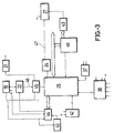
- the figure number 3 shows again a second diagram that complements the one represented in the figure number 2.
- this is configurated through a Data Collection Centre, a Telemetering Remote Unit and a Deposit Unit.
- the Data Collection Centre has a PC available, provided with two installed modems, which allow the reception of telephone calls or via radio, coming from each Telemetering Remote Unit that is assigned to the corresponding centre.
- Telemetering Remote Unit When the Telemetering Remote Unit communicates with the centre, it displays the messages that indicate the communication condition.
- the data base of the Data Collection Centre are configurated as a data base deposit parameters and a data base of the deposit conditions.
- the parameters data base contain all the programming parameters or configuration of each deposit and of the corresponding Telemetering Remote Unit associated with.
- the data base of deposit conditions contains the condition of each deposit updated with each received call.
- the centre has the capacity to generate reports with the data received in the communications, generating two types of information:
- the centre daily, at a previously programmed time, the centre generates through the printer, a report with the registered incidences in the last 24 hours, that is, the daily report.
- This report contains a list with the deposits that have called and their general condition, that is, if they are in normal condition or have had some incidence.
- the centre provides a man/machine interface, that is organized in a series of menus that allow the performance of various operations, such as obtaining reports, handling of the data base, etc., etc.
- the menus display consists of a window in the PC monitor in which different options appear in the upper part to be selected by the user.
- the operator has access to all the operations related to the data base, while the manager is in charge of the application maintenance.
- the existence of the alarms report is contemplated in the reports, in which appear the Telemetering Remote Unit condition, the maintenance incidence, the empty deposit, the overfull deposit, the refilled deposit, the anticorrosion alarm, the malfunctioning possibility of the level sensor, the communication failure possibility with the deposit unit, the existence of low tension in the deposit unit, the service alarms and the user alarms.
- the deposit number which is configurated as an identical field as the data base parameters, existing a gas level base that is configurated as the deposit gas level at the time of the last call expressed in %, it can be said regarding the corrosion tension considered in the base of deposit conditions that this corrosion level is expressed in Volts.
- the Telemetering Remote Unit is the equipment in charge of reading the analogical values obtained from the sensors, level and corrosion, located in the deposit. Likewise, it carries out the processing of the above mentioned values as may be the conversion analog-digital, memorizing, codification, etc. for their later transmission, using the switch-over telephone network or via radio towards the Data Collection Centre.
- the Telemetering Remote Unit also communicates to the Data Collection Centre, its own alarms and receives from it the necessary data for the programming and its functioning.
- Telemetering Remote Units depending on the connection form to the deposit, either by direct connection, through cable or via radio, being necessary in this case to use the deposit unit and the type of feeding received, this connection being by network or by telefeeding.
- the period of rest is obviously characterized by the lack of feeding to the blocks that constitute the unit with the exception of the processing nucleus that remains fed but stopped and the real time clock that remains always functioning.
- the clock is in charge of calculating the time of functioning, connecting the feeding to the functioning blocks to start an activity period, in which it is considered the deposits data gathering, inputs inspection and the communication with the Data Collection Centre.
- the invention considers the possibility that in the case that a detection of an abnormal condition exists, an activity period is assigned to carry out more than one of the previous processes.
- An operator can produce the starting of the Telemetering Remote Unit through a push-button located in a lateral area thereof, so that with the help of the keyboard unit and the pertinent display, carrying out the initiation functions producing an incidence call or deposit unit synchronisation if the connection is via radio.
- the data read from the sensors are processed and give rise to the deposit alarms, controlling the Telemetering Remote Unit to its own functioning and generating the indicating calls of the Telemetering Remote Unit condition, controlling at last the inputs situation, giving rise to the alarms to indicate the condition of the four inputs system and alarms that indicate the condition of the user four inputs.
- the alarms and conditions of the Telemetering Remote Unit are the following:
- Another alarm indicates that a refilling of the deposit has been produced, activating itself when between two data readings an increase is detected in the deposit level of 20% and is deactivated when is transmitted to the centre.
- This alarm is activated when a communication attempt fails and is deactivated when the correct message is received or when it is transmitted to the Data Collection Centre.
- the invention has available a checking system for the Telemetering Remote Unit conditions, that indicate that the battery of that unit is low and it is necessary to change it, activating this alarm when the reading of the battery tension is below the required minimum for the normal functioning.
- the condition of the battery is read in the programme data readings, both in low charge and in maximum charge and it is deactivated every time the communication is made with the centre or if in the readings at maximum charge the correct tension level is detected.
- this unit has an alarm that indicates a failure in the communication when the unit emits its messages via radio.
- the condition of the clock installed in the Telemetering Remote Unit is verified by an alarm that is activated when communicating with the Data Collection Centre, a failure is detected, such as may be when the time that is sending differs in more than two minutes with the time of the Telemetering Remote Unit, deactivating in the moment that is communicating to the centre or when the difference is lower than two minutes.
- an alarm sets in motion.
- the invention is configurated from a connection (1) to the network, with or without ground connection, from which three conventional colour cables blue, green and brown (2) are originated, which are connected with a general module (3) in which there is integrated a radio module (12) supplied with its receiving antenna pertinent cable (13), originated from the general module (3) some connections up to an interconnection box (5) to the telephone line (4), having a central or main module (3) of the pertaining connection to an extension cable for connections (15) with its corresponding connection (6) to a telephone (7).
- a microcontroller is incorporated (25) joined on one hand to the real time clock block RTC (23) and on the other hand to the radio feeding control (24) with the block (27) assigned to be used as radio module connector.
- the microcontroller (25) is connected with the system/user input interface (39) and at the same time with the battery supervision block (37) just as with the interface with sensors (38) and this one with the line relays excitation block (36) and at the same time this last one with the multifrequency generation block (35).
- the block (35) is connected to the telephone line interface (28) and the modem and tones detector (29) connected at the same time with the microcontroller (25), existing an auxiliary connection from the telephone line interface (28) to the unhooking telephone detector (34).
- the microcontroller (25) is connected to an external programming interface (42), to a RTC lock (44), which at the same time communicates with the block (43) corresponding to the initiation circuit, having pertinent connections, the blocks (43) and (44) in order to connect with the batteries block (19), to feeding control block (22), which at the same time is connected through a main feeding connection (46) to the tension regulator (45) and this one at the same time to the tension block of reference (21).
- the microcontroller (25) communicates or connects with the radio feeding control block (24), connected through a feeding and stop cable (47) to a radio module connector (27) that receives communication from the transversal filter (49) and this one at the same time from the starcom block (48) connected with the microcontroller (25).
Landscapes
- Physics & Mathematics (AREA)
- General Physics & Mathematics (AREA)
- Fluid Mechanics (AREA)
- Engineering & Computer Science (AREA)
- Signal Processing (AREA)
- Arrangements For Transmission Of Measured Signals (AREA)
Applications Claiming Priority (2)
| Application Number | Priority Date | Filing Date | Title |
|---|---|---|---|
| ES09302049A ES2079285B1 (es) | 1993-09-28 | 1993-09-28 | Sistema de telemedida de gases licuados de petroleo. |
| ES9302049 | 1993-09-28 |
Publications (2)
| Publication Number | Publication Date |
|---|---|
| EP0645610A2 true EP0645610A2 (fr) | 1995-03-29 |
| EP0645610A3 EP0645610A3 (fr) | 1995-05-10 |
Family
ID=8283172
Family Applications (1)
| Application Number | Title | Priority Date | Filing Date |
|---|---|---|---|
| EP94500158A Withdrawn EP0645610A3 (fr) | 1993-09-28 | 1994-09-23 | Système télémétrique pétrole-gas liquifié. |
Country Status (2)
| Country | Link |
|---|---|
| EP (1) | EP0645610A3 (fr) |
| ES (1) | ES2079285B1 (fr) |
Cited By (3)
| Publication number | Priority date | Publication date | Assignee | Title |
|---|---|---|---|---|
| DE29618256U1 (de) * | 1996-10-21 | 1996-12-12 | Tank-Security Vertriebs GmbH, Salzburg | Überwachungsgerät für den Füllstand von Tankanlagen |
| WO2003025875A1 (fr) * | 2001-09-21 | 2003-03-27 | Sydkraft Ab | Terminal, serveur, procede et accessoire pour la distribution a distance de services d'information |
| CN116798196A (zh) * | 2023-08-28 | 2023-09-22 | 湖南天联城市数控有限公司 | 燃气安全报警方法、设备及可读存储介质 |
Citations (4)
| Publication number | Priority date | Publication date | Assignee | Title |
|---|---|---|---|---|
| US4713837A (en) * | 1985-12-24 | 1987-12-15 | Alastair Gordon | Communication network |
| EP0260788A2 (fr) * | 1986-09-12 | 1988-03-23 | Scully Signal Company | Système domestique de signalisation et d'alarme pour le niveau du mazout |
| EP0264311A1 (fr) * | 1986-09-16 | 1988-04-20 | ELF FRANCE, Société Anonyme dite: | Méthode de transmission de données d'information ou de mesure et dispositif de mise en oeuvre de la méthode |
| EP0526686A1 (fr) * | 1991-06-10 | 1993-02-10 | Daimler-Benz Aerospace Aktiengesellschaft | Système intelligent de télémesure et d'actionnement |
Family Cites Families (6)
| Publication number | Priority date | Publication date | Assignee | Title |
|---|---|---|---|---|
| US4523460A (en) * | 1983-12-06 | 1985-06-18 | Montech Systems Incorporated | Fluid measuring, testing and accounting system |
| FR2588983A1 (fr) * | 1985-10-17 | 1987-04-24 | Rambaud Guy | Procede et systeme d'indication automatique a distance de niveaux de liquides dans les reservoirs ou citernes fixes |
| FR2600147B1 (fr) * | 1986-06-16 | 1990-06-29 | Arizzoli Bernard Perre Ets | Installation pour la gestion d'une quantite de liquide, notamment de fioul domestique, contenue dans une cuve de stockage |
| MY106078A (en) * | 1988-12-26 | 1995-03-31 | Tokyo Tatsuno Kk | System for radio transmission of liquid level data and for converting received data to volume data to be indicated. |
| GB8922110D0 (en) * | 1989-09-30 | 1989-11-15 | Fredk H Burgess P L C | Delivery system |
| US5154079A (en) * | 1991-09-30 | 1992-10-13 | Lupoli Peter A | Remote indicator attachment kit |
-
1993
- 1993-09-28 ES ES09302049A patent/ES2079285B1/es not_active Expired - Lifetime
-
1994
- 1994-09-23 EP EP94500158A patent/EP0645610A3/fr not_active Withdrawn
Patent Citations (4)
| Publication number | Priority date | Publication date | Assignee | Title |
|---|---|---|---|---|
| US4713837A (en) * | 1985-12-24 | 1987-12-15 | Alastair Gordon | Communication network |
| EP0260788A2 (fr) * | 1986-09-12 | 1988-03-23 | Scully Signal Company | Système domestique de signalisation et d'alarme pour le niveau du mazout |
| EP0264311A1 (fr) * | 1986-09-16 | 1988-04-20 | ELF FRANCE, Société Anonyme dite: | Méthode de transmission de données d'information ou de mesure et dispositif de mise en oeuvre de la méthode |
| EP0526686A1 (fr) * | 1991-06-10 | 1993-02-10 | Daimler-Benz Aerospace Aktiengesellschaft | Système intelligent de télémesure et d'actionnement |
Cited By (4)
| Publication number | Priority date | Publication date | Assignee | Title |
|---|---|---|---|---|
| DE29618256U1 (de) * | 1996-10-21 | 1996-12-12 | Tank-Security Vertriebs GmbH, Salzburg | Überwachungsgerät für den Füllstand von Tankanlagen |
| WO2003025875A1 (fr) * | 2001-09-21 | 2003-03-27 | Sydkraft Ab | Terminal, serveur, procede et accessoire pour la distribution a distance de services d'information |
| CN116798196A (zh) * | 2023-08-28 | 2023-09-22 | 湖南天联城市数控有限公司 | 燃气安全报警方法、设备及可读存储介质 |
| CN116798196B (zh) * | 2023-08-28 | 2023-10-27 | 湖南天联城市数控有限公司 | 燃气安全报警方法、设备及可读存储介质 |
Also Published As
| Publication number | Publication date |
|---|---|
| ES2079285R (fr) | 1996-12-01 |
| ES2079285A2 (es) | 1996-01-01 |
| EP0645610A3 (fr) | 1995-05-10 |
| ES2079285B1 (es) | 1997-07-01 |
Similar Documents
| Publication | Publication Date | Title |
|---|---|---|
| CA2202584C (fr) | Methode et dispositif remplissant les fonctions de registre a un noeud commun pour une pluralite d'appareils de mesure electrique | |
| US5719564A (en) | Utility meter reading system | |
| US6369719B1 (en) | Apparatus and method for collecting and transmitting utility meter data and other information via a wireless network | |
| RU2314542C2 (ru) | Система дистанционного сбора данных о потреблении электрической энергии и дистанционного управления распределенными пользовательскими пунктами, также и бытового типа | |
| KR930004008B1 (ko) | 원격 계측 터미널 | |
| CA1155243A (fr) | Appareil et methode pour la surveillance, la mesure et la commande a distance | |
| US20200055744A1 (en) | Systems and Methods for Distributed Utilities | |
| Tamarkin | Automatic meter reading | |
| US6665620B1 (en) | Utility meter having primary and secondary communication circuits | |
| US20030025612A1 (en) | Wireless end device | |
| US4682169A (en) | Method of and system for accumulating verifiable energy demand data from remote electricity meters | |
| EP0527072A2 (fr) | Système d'acquisition de données par des appels téléphoniques entrant avec capacité de lecture à la demande | |
| US20080088464A1 (en) | Power System Architecture for Fluid Flow Measurement Systems | |
| NZ238245A (en) | Remote utility meter reading: encoded interrogation signal | |
| US20030016142A1 (en) | Two-way wide area telemetry | |
| CA2108978C (fr) | Reseau de communication grande distance pour stations eloignees generatrices de donnees | |
| US20020030604A1 (en) | Telemetry system and method | |
| GB2297663A (en) | Remote meter reading | |
| US20020039069A1 (en) | System and method for remote monitoring of cathodic protection systems | |
| US4697180A (en) | System for accumulating verifiable energy demand data from remote electricity meters | |
| EP0645610A2 (fr) | Système télémétrique pétrole-gas liquifié | |
| CA2404625C (fr) | Systeme et methode pour obtenir des donnees relativement a une installation | |
| EP1649717B1 (fr) | Systemes et procedes pour services publics repartis | |
| CA2608603C (fr) | Methode et dispositif remplissant les fonctions de registre a un noeud commun pour une pluralite d'appareils de mesure electrique | |
| EP1365542A1 (fr) | Appareil et procédé de détection d'évènements par un réseau Ethernet |
Legal Events
| Date | Code | Title | Description |
|---|---|---|---|
| PUAI | Public reference made under article 153(3) epc to a published international application that has entered the european phase |
Free format text: ORIGINAL CODE: 0009012 |
|
| PUAL | Search report despatched |
Free format text: ORIGINAL CODE: 0009013 |
|
| AK | Designated contracting states |
Kind code of ref document: A2 Designated state(s): DE FR IT |
|
| AK | Designated contracting states |
Kind code of ref document: A3 Designated state(s): DE FR IT |
|
| RHK1 | Main classification (correction) |
Ipc: H04M 11/00 |
|
| 17P | Request for examination filed |
Effective date: 19951103 |
|
| STAA | Information on the status of an ep patent application or granted ep patent |
Free format text: STATUS: THE APPLICATION IS DEEMED TO BE WITHDRAWN |
|
| 18D | Application deemed to be withdrawn |
Effective date: 19990401 |