EP0645492A1 - Apparatus for cutting railroad rails - Google Patents
Apparatus for cutting railroad rails Download PDFInfo
- Publication number
- EP0645492A1 EP0645492A1 EP93307632A EP93307632A EP0645492A1 EP 0645492 A1 EP0645492 A1 EP 0645492A1 EP 93307632 A EP93307632 A EP 93307632A EP 93307632 A EP93307632 A EP 93307632A EP 0645492 A1 EP0645492 A1 EP 0645492A1
- Authority
- EP
- European Patent Office
- Prior art keywords
- rail
- cutting
- locating frame
- railroad
- arm
- Prior art date
- Legal status (The legal status is an assumption and is not a legal conclusion. Google has not performed a legal analysis and makes no representation as to the accuracy of the status listed.)
- Granted
Links
Images


Classifications
-
- E—FIXED CONSTRUCTIONS
- E01—CONSTRUCTION OF ROADS, RAILWAYS, OR BRIDGES
- E01B—PERMANENT WAY; PERMANENT-WAY TOOLS; MACHINES FOR MAKING RAILWAYS OF ALL KINDS
- E01B31/00—Working rails, sleepers, baseplates, or the like, in or on the line; Machines, tools, or auxiliary devices specially designed therefor
- E01B31/02—Working rail or other metal track components on the spot
- E01B31/04—Sectioning or slitting, e.g. by sawing, shearing, flame-cutting
-
- B—PERFORMING OPERATIONS; TRANSPORTING
- B23—MACHINE TOOLS; METAL-WORKING NOT OTHERWISE PROVIDED FOR
- B23D—PLANING; SLOTTING; SHEARING; BROACHING; SAWING; FILING; SCRAPING; LIKE OPERATIONS FOR WORKING METAL BY REMOVING MATERIAL, NOT OTHERWISE PROVIDED FOR
- B23D45/00—Sawing machines or sawing devices with circular saw blades or with friction saw discs
- B23D45/006—Sawing machines or sawing devices with circular saw blades or with friction saw discs with means to attach the sawing device to the workpiece
-
- B—PERFORMING OPERATIONS; TRANSPORTING
- B23—MACHINE TOOLS; METAL-WORKING NOT OTHERWISE PROVIDED FOR
- B23D—PLANING; SLOTTING; SHEARING; BROACHING; SAWING; FILING; SCRAPING; LIKE OPERATIONS FOR WORKING METAL BY REMOVING MATERIAL, NOT OTHERWISE PROVIDED FOR
- B23D45/00—Sawing machines or sawing devices with circular saw blades or with friction saw discs
- B23D45/04—Sawing machines or sawing devices with circular saw blades or with friction saw discs with a circular saw blade or the stock carried by a pivoted lever
- B23D45/042—Sawing machines or sawing devices with circular saw blades or with friction saw discs with a circular saw blade or the stock carried by a pivoted lever with the saw blade carried by a pivoted lever
- B23D45/046—Sawing machines or sawing devices with circular saw blades or with friction saw discs with a circular saw blade or the stock carried by a pivoted lever with the saw blade carried by a pivoted lever the pivoted lever being mounted on a carriage
-
- F—MECHANICAL ENGINEERING; LIGHTING; HEATING; WEAPONS; BLASTING
- F02—COMBUSTION ENGINES; HOT-GAS OR COMBUSTION-PRODUCT ENGINE PLANTS
- F02B—INTERNAL-COMBUSTION PISTON ENGINES; COMBUSTION ENGINES IN GENERAL
- F02B1/00—Engines characterised by fuel-air mixture compression
- F02B1/02—Engines characterised by fuel-air mixture compression with positive ignition
- F02B1/04—Engines characterised by fuel-air mixture compression with positive ignition with fuel-air mixture admission into cylinder
Definitions
- the present invention relates to railroad rail cutting apparatus, and particularly concerns apparatus for in situ cutting of railroad rails to specified lengths during laying or joining of railroad rails.
- Cutting machines having flat, rotary grinding disk saws that are driven by a power source to cut rails to specified lengths are employed during the laying of railroad rails and the replacement of worn rails.
- Conventional cutting machines are of a configuration whereby the main body is clamped to the railroad rail and the grinding disk saw is advanced in a specified single direction while the grinding disk saw is rotated. Because of this single direction of advance of the blade, the entire width of the head of the rail is cut crosswise without changing the contact position of the grinding disk saw with respect to the railroad rail.
- the present invention devised out of the need to address such drawbacks of the prior art, has as its object the provision of a high-performance rail cutting machine wherein high-precision cutting is performed with a narrow cut to prevent hardening of the rail, a small, light power source is used for easy handling, and the positioning of the cutting machine is easily made.
- a rail clamping means is configured wherein a railroad rail of specified cross-section is cross clamped on two sides, this being achieved by means of a clamp arm supported for rotation by a locating frame.
- a clamp position is determined by tightening the lower end of a clamp screw, which is threaded vertically down through a threaded cylinder sleeve positioned on the upper surface of the clamp arm onto a locating recess or countersink on the surface of a gauge removably secured on the running surface of the railroad rail for indicating the cutting position.
- Rail clamping is further enhanced by rail holding abutment members selectively positioned on the locating frame for holding the railroad rail with significant vertical and horizontal pressure applied perpendicularly to the railroad rail, between the locating frame and a lower jaw provided on the clamp arm.
- Two slide shafts which are juxtaposed horizontally and support a main body for sliding movement relative to the locating frame, are secured to the locating frame at their ends to extend horizontally, perpendicularly with respect to the railroad rail.
- a stroke handle extending upward and swingably supported by the locating frame, is connected to the main body by a connecting bar so as to swing relative to the main body.
- a cutting arm extending laterally with respect to the rail from the upper part of the main body, is adapted to swing vertically in a plane parallel to the slide shafts, and a uniform cutting pressure is provided by means of the resilience of springs.
- This cutting arm is provided with an arm handle attached thereto, to allow manual adjustment of the cutting arm.
- a grinding disk saw which is rotated by a power source and forms a crosswise cut in the railroad rail corresponding to the cut position indicated by the gauge, is detachably mounted on the free end of the cutting arm.
- an angle of about 45° is formed between the upper surface of the railroad rail and the radius extending from the axis of rotation of the grinding disk saw to a point of contact at which the grinding disk saw contacts with the corner of the railroad rail and the cutting position of the grinding disk saw relative to the railroad rail can be continuously varied during cutting by forward and backward strokes of the stroke handle which cause the cutting arm pivot axis to move towards or away from the rail.
- the clamping means provided on the locating frame preferably comprises rail jaw abutments juxtaposed opposite the lower end of the clamp screw to engage the tapered under surface of the head of the rail with a substantial pressure so as to clamp the rail head from both above and below, and medial rail abutments, juxtaposed opposite the lower jaw of the clamp arm to hold the central web of the rail with a substantial pressure, and a rail head lateral abutment positioned on the same side of the rail as the medial rail abutments to engage the side of the rail head.
- the main body block 1 is slidingly supported on two juxtaposed parallel slide shafts 2.
- the ends 2a of each of these slide shafts 2 are threaded.
- a locating frame 3 which has a generally U-shaped longitudinal section formed by front and back wall surfaces 3a, 3b and a ceiling surface 3c, is formed with through holes 3d side by side in the back wall 3a as viewed when its open side is faced downward, (the left side as viewed in Figures 1 and 3).
- the threaded parts 2a at the ends (the right-hand side as viewed in Figures 1 and 3) of the slide shafts 2 are fastened by nuts in said through holes 3d.
- through holes 3d are formed so that slide shafts 2 fastened in the through holes 3d extend perpendicularly with respect to front wall surface 3b of locating frame 3.
- Various supports are provided on the interior of the front wall 3b of locating frame 3, which faces one longitudinal surface of a railroad rail 5 of specific cross-section held between wall surfaces 3a and 3b, as seen in Figure 3. That is, as the position and direction of these rail supports are indicated by arrows in Figure 5, the central web 5a of the rail 5 is supported horizontally at two points, the under surface 5b of the head 5c of the rail 5 is supported horizontally at two points, and the side surface of the rail head 5c is supported at one central point.
- the rail support means comprising the two juxtaposed medial rail abutments 6a, the two juxtaposed rail jaw abutments 6b, and the single rail top abutment 6c, is configured so as to bring front wall surface 3b into uniform contact with railroad rail 5, and to position the front wall 3b in a plane parallel to the plane of symmetry of the rail.
- U-shaped clamp arm 4 having lower a jaw 4a positioned at its lower end and threaded cylindrical sleeve 4b at its upper end is installed in a space formed in locating frame 3, and the curved portion of clamp arm 4 is supported for pivoting movement by a shaft 7 extending parallel to the rail 5 through two flange members 3e of locating frame 3.
- the threaded part 8b of a clamp screw 8 is screwed vertically down through the threaded cylindrical sleeve 4b by turning handle 8a so as to bring the lower end 8c to extend downward.
- a line projected vertically downward through the lower end 8c of clamp screw 8 is located at approximately the centre between medial rail abutments 6a and top rail abutment 6b. This configuration permits clamp screw 8 to be tightened in a stable manner.
- a gauge 9 has a clamping strip 9b, secured to one end of a flat plate, which is tightly fastened onto the upper surface of railroad rail 5 of specified width from above, and a high-pressure clamping strip 9c, secured to the other end, which is fastened onto railroad rail 5 in a similar manner to fastening the clamping strip 9b.
- a knurled or wing-type fastening screw 9d one side of high-pressure clamping strip 9c is fastened to the side surface of the rail head 5c.
- the end of the flat plate adjacent the clamping strip 9b indicates the cutting position 10.
- gauge 9 is first mounted on the surface of railroad rail 5, and the cutting apparatus is automatically positioned and secured in the required position on railroad rail 5 by tightening clamp screw 8 to bring its lower end 8c itself into abutment with the countersink 9a of gauge 9.
- An expected cutting line corresponding to the cutting position 10 is accurately perpendicular to the lengthwise direction of railroad rail 5.
- the distance between the recess or countersink 9a bored in the upper surface of gauge 9 and the end of the gauge corresponds to the distance between the plane of the cutting saw and the lower end 8c of clamp screw 8.
- railroad rail 5 can be clamped perpendicularly in vertical and horizontal directions by simply tightening the single clamp screw 8 onto countersink 9a of gauge 9, and main body 1 can be slid horizontally perpendicularly with respect to the axis of railroad rail 5.
- an upwardly extending stroke handle 11 is supported for swinging movement by shaft 11a.
- Protruding member 16a of a support shaft 16 which is provided so as to extend from the side of upper support members 1a of main body 1, is connected to the middle of stroke handle 11 by connecting bar 12 so as to be movable relative to each other. By swinging the stroke handle 11, the main body 1 can be moved towards and away from the locating frame 3.
- main body 1 can be horizontally advanced or withdrawn with respect to railroad rail 5 by moving stroke handle 11 forward or backward by hand.
- a rubber hand grip 11b is shown on stroke handle 11.
- Stroke handle 11 can be locked in the forwardly inclined position by being hooked on a handle hook 11d through a stopper 11c positioned on a laterally protruding member of locating frame 3.
- the threaded portions 2a of the ends of slide shafts 2 remote from locating frame 3 are anchored in a support member 14 which is equipped with wheels 13 on both ends.
- This support member 14 is provided with a stop 14a, capable of abutting the side of main body 1 to lessen the impact on support 14 when main body 1 moves forward or backward.
- carrying handles 15 are secured to both sides of main body 1. Rubber hand grips 15a are placed over the ends of carrying handles 15.
- a cutting arm 17 is mounted for swing movement on support member 1a, on the upper part of main body 1, by a support shaft 16.
- the cutting arm 17 is mounted so as to swing perpendicularly to the lengthwise direction of railroad rail 5 once locating frame 3 has been clamped on railroad rail 5 in the manner set forth above, i.e. the cutting arm 17 swings in a plane parallel to the guide bars 2.
- Cutting arm 17 is configured to have a free end protruding toward locating frame 3.
- a support plate 19 is provided on the cutting arm 17 in a position where cutting arm 17 is pivoted, i.e. above main body 1.
- an engine 18 is bolted through an intermediate plate 20 so as to place the end of its output shaft 18a adjacent to cutting arm 17.
- This engine 18 may be an internal combustion type or an electric motor.
- the engine shown in the drawings is of a combustion type and is provided with necessary devices such as fuel tank 42, starter lever 41, etc.
- the lengthwise position of engine 18 may be adjusted by screwing in and out the adjustment bolt 20a.
- Cylindrical members 23a are provided on both ends of an attachment plate 23 facing support shafts 22 which protrude toward the rear on both sides of support plate 19.
- the ends of support shafts 22 are held and secured by washers 24a, preventing slipping off of coil springs 24.
- the lower side surface of attachment plate 23 is bolted to the back surface of support members 1a of main body 1.
- Stopper 23b extending upward, is secured via a bracket to the side of attachment plate 23 and is adapted to abut against the bottom of support plate 19 so as to restrict the amount the cutting arm 17 swings toward the rear.
- the free end of cutting arm 17 is divided to form two plates 17a, one of which has attached thereto an upwardly extending handle 26, with a grip 26a.
- Handle 26 can be locked in a forward position by hooking it on a handle hook 26d via a stopper 26c positioned on a protruding side member of locating frame 3.
- Cutting arm 17 is formed with mounting holes 27 in plates 17a to permit installation of flanged rotary shaft 28 for rotation.
- Flanged rotary shaft 28 is inserted into mounting holes 27 leaving the flange portion exposed on the exterior.
- Pulley 31 is secured between the plates 17a on one end 28a of shaft 28 protruding from the inner side of rotation shaft 28 so as to rotate together with shaft member 28a.
- Bearings 29 are positioned on both sides of pulley 31, and the end 28a of shaft 28 is secured with a nut fitting bearing 29 against mounting holes 27 on plates 17a.
- a flat grinding disk saw 30 is abutted against the flange portion of flanged rotary shaft 28 and detachably secured to the shaft 28 from the outside via a flange 33 with a nut 34.
- Belt 35 is then placed over the pulley 31 positioned between plates 17a and over a pulley 32 secured on output shaft 18a of engine 18.
- the grinding disk saw 30 is attached so that the plane of grinding disk saw 30 is perpendicular to the lengthwise direction of railroad rail 5.
- a cover 36a for the belt 35 and a cover 36b for the grinding disk saw 30, are mounted on cutting arm 17.
- an arm lock lever 37 is pivotally supported by a shaft on the top of main body 1 as shown at the lower right of Figure 2.
- This arm lock lever 37 is also linked to main body 1 via spring 39.
- a notched tab 37a secured to the middle of arm lock lever 37 automatically catches on a small shaft 38 protruding in close proximity to the support of the cutting arm 17 when the cutting arm is raised to a certain degree.
- handle 26 is slightly raised so as to lift cutting arm 17 upward, and then arm lock lever 37 is pulled forward so as to release the engagement between notched tab 37a and shaft 38.
- cutting arm 17 pivots about the pivot axis A (support shaft 16), and is positioned so that an angle of approximately 45° is formed between the upper surface of rail 5 and the radius of grinding disk saw 30 from the axis of rotation B to the point C where grinding disk saw 30 contacts with the corner of rail 5. While the cutting arm 17 is constrained to swing about support shaft 16, it varies in position due to its own weight and forces exerted by coil springs 24, so as to provide a uniform cutting pressure to the cut in rail 5 formed by grinding disk saw 30. By moving main body 1 forward and backward, rotating grinding disk saw 30 is smoothly moved along the kerf of the cut in rail 5.
- a certain clearance X between the lowest position of locating frame 3 and the surface of the ground is desirable to permit direct cutting of rails already secured in position.
- stroke handle 11 and handle 26 are first engaged and locked by handle locks 11d and 26d, respectively. One person then lifts stroke handle 11 and handle 26, and another person lifts both carrying handles 15.
- handle lock 26d on handle 26 is released and handle 26 is raised.
- Notched tab 37a on arm lock lever 37 then catches and locks shaft 38 of cutting arm 17, fixing the cutting arm 17 in a raised position.
- Grinding disk saw 30 is then placed on shaft member 28a of flanged rotary shaft 28 and, as shown in Figure 2, secured with nut 34 via flange 33 using a wrench 40.
- the gauge 9 is fixed on the railroad rail to be cut, with the cutting position 10 indicated by gauge 9 aligned with the intended cutting line on the railroad rail 5.
- the clamp of the cutting apparatus is lifted and seated on railroad rail 5, the lower end 8c of clamp screw 8 is fitted into counters ink 9a of gauge 9, and clamp screw 8 is then tightened.
- handle hook 11d of stroke handle 11 is disengaged and handle 26 is raised so that grinding disk saw 30 is moved away from railroad rail 5. In this position, engine 18 is then started and left idling.
- handle 26 is slightly raised (in the direction of the black arrow in Figure 12) and arm lock lever 37 is pulled forward to free cutting arm 17. While handle 26 is then steadily lowered (in the direction of the white arrow in Figure 13), grinding disk saw 30 is brought into contact with the upper part of the rail 5. The engine is fully powered up once a small cut has been made in the top part of rail 5.
- stroke handle 11 While holding handle 26 enough to prevent grinding disk saw 30 from rocking up and down, stroke handle 11 is moved back and forth about 30cm at intervals of 1 to 2 seconds to cut the railroad rail.
- Figure 14 shows the back of the present cutting machine mounted on a railroad rail 5.
- the present cutting machine is clamped in a position higher than the bottom of railroad rail 5 as indicated by an arrow H, the railroad rail 5 can be cut without first being lifted.
- removal of ballast 41 to a depth of 10cm below the location of the cut made by the rotating grinding disk saw is desirable.
- the present invention as described above, thus provides an apparatus for cutting rails to specific lengths, the cutting machine being readily positionable on the rail for a given cut.
- the apparatus is suitable for cutting railroad rails where they have been laid, and is convenient for emergency railroad rail replacement.
- the rotating grinding desk saw is smoothly moved along the line of the cut, varying the cutting position of said rotating grinding disk saw.
- the rail is therefore not hardened, and cutting requires much less torque. Since a small, light power source can thus be used, the rotating grinding disk saw has no propensity for deflection, and thin, precise cuts are made.
- Weight reduction also simplified operations such as transport, handling and setting.
Landscapes
- Engineering & Computer Science (AREA)
- Mechanical Engineering (AREA)
- Architecture (AREA)
- Civil Engineering (AREA)
- Structural Engineering (AREA)
- Machines For Laying And Maintaining Railways (AREA)
- Finish Polishing, Edge Sharpening, And Grinding By Specific Grinding Devices (AREA)
Abstract
Description
- The present invention relates to railroad rail cutting apparatus, and particularly concerns apparatus for in situ cutting of railroad rails to specified lengths during laying or joining of railroad rails.
- Cutting machines having flat, rotary grinding disk saws that are driven by a power source to cut rails to specified lengths are employed during the laying of railroad rails and the replacement of worn rails.
- Conventional cutting machines are of a configuration whereby the main body is clamped to the railroad rail and the grinding disk saw is advanced in a specified single direction while the grinding disk saw is rotated. Because of this single direction of advance of the blade, the entire width of the head of the rail is cut crosswise without changing the contact position of the grinding disk saw with respect to the railroad rail.
- In such a cutting method, since the grinding disk saw continuously rotates keeping the same cutting line as given at first contact, not only is a large amount of frictional heat generated and consequently the rail is hardened in the region of the cut, but also a large engine is required to drive the rotary grinding disk saw due to this large friction. Then, vibration is readily transmitted to the rotary grinding disk saw and substantial cutting pressure is needed, which causes widened and deflected cuts, impeding high-precision cutting.
- The present invention, devised out of the need to address such drawbacks of the prior art, has as its object the provision of a high-performance rail cutting machine wherein high-precision cutting is performed with a narrow cut to prevent hardening of the rail, a small, light power source is used for easy handling, and the positioning of the cutting machine is easily made.
- In a cutting machine for railroad rails according to the present invention, a rail clamping means is configured wherein a railroad rail of specified cross-section is cross clamped on two sides, this being achieved by means of a clamp arm supported for rotation by a locating frame. A clamp position is determined by tightening the lower end of a clamp screw, which is threaded vertically down through a threaded cylinder sleeve positioned on the upper surface of the clamp arm onto a locating recess or countersink on the surface of a gauge removably secured on the running surface of the railroad rail for indicating the cutting position. Rail clamping is further enhanced by rail holding abutment members selectively positioned on the locating frame for holding the railroad rail with significant vertical and horizontal pressure applied perpendicularly to the railroad rail, between the locating frame and a lower jaw provided on the clamp arm. Two slide shafts, which are juxtaposed horizontally and support a main body for sliding movement relative to the locating frame, are secured to the locating frame at their ends to extend horizontally, perpendicularly with respect to the railroad rail. A stroke handle, extending upward and swingably supported by the locating frame, is connected to the main body by a connecting bar so as to swing relative to the main body. A cutting arm, extending laterally with respect to the rail from the upper part of the main body, is adapted to swing vertically in a plane parallel to the slide shafts, and a uniform cutting pressure is provided by means of the resilience of springs. This cutting arm is provided with an arm handle attached thereto, to allow manual adjustment of the cutting arm. A grinding disk saw, which is rotated by a power source and forms a crosswise cut in the railroad rail corresponding to the cut position indicated by the gauge, is detachably mounted on the free end of the cutting arm. Preferably, an angle of about 45° is formed between the upper surface of the railroad rail and the radius extending from the axis of rotation of the grinding disk saw to a point of contact at which the grinding disk saw contacts with the corner of the railroad rail and the cutting position of the grinding disk saw relative to the railroad rail can be continuously varied during cutting by forward and backward strokes of the stroke handle which cause the cutting arm pivot axis to move towards or away from the rail.
- Moreover, the clamping means provided on the locating frame preferably comprises rail jaw abutments juxtaposed opposite the lower end of the clamp screw to engage the tapered under surface of the head of the rail with a substantial pressure so as to clamp the rail head from both above and below, and medial rail abutments, juxtaposed opposite the lower jaw of the clamp arm to hold the central web of the rail with a substantial pressure, and a rail head lateral abutment positioned on the same side of the rail as the medial rail abutments to engage the side of the rail head.
- An embodiment of the present invention will now be described in detail with reference to the accompanying drawings, in which:
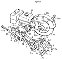
- Figure 1 is an overall perspective view of the railroad rail cutting apparatus of the present invention;
- Figure 2 is an exploded perspective view of the cutting apparatus of the present invention;
- Figure 3 is a side view of a railroad rail clamp mechanism of the cutting apparatus of the present invention;
- Figure 4 is a perspective view of a gauge to indicate a cut position, shown mounted on the upper surface of the railroad rail;
- Figure 5 is a explanatory schematic perspective view showing the engagement of the apparatus with a rail;
- Figure 6 is a schematic side view showing the mounting position of the main body block of the cutting apparatus relative to a rail;
- Figures 7a to 7c are illustrations showing the change in cutting engagement of the rotary grinding disk saw with the rail; and
- Figures 8 to 14 are perspective views illustrating various stages in the operation of the cutting apparatus of the present invention.
- Referring now to the drawings, in Figures 1 and 2, the
main body block 1 is slidingly supported on two juxtaposedparallel slide shafts 2. In addition to passing throughmain body block 1 from front to back, the ends 2a of each of theseslide shafts 2 are threaded. - As shown In Figure 3, a locating
frame 3, which has a generally U-shaped longitudinal section formed by front andback wall surfaces ceiling surface 3c, is formed with throughholes 3d side by side in theback wall 3a as viewed when its open side is faced downward, (the left side as viewed in Figures 1 and 3). The threaded parts 2a at the ends (the right-hand side as viewed in Figures 1 and 3) of theslide shafts 2 are fastened by nuts in said throughholes 3d. - In this instance, through
holes 3d are formed so thatslide shafts 2 fastened in the throughholes 3d extend perpendicularly with respect tofront wall surface 3b of locatingframe 3. - Various supports are provided on the interior of the
front wall 3b of locatingframe 3, which faces one longitudinal surface of arailroad rail 5 of specific cross-section held betweenwall surfaces central web 5a of therail 5 is supported horizontally at two points, the undersurface 5b of thehead 5c of therail 5 is supported horizontally at two points, and the side surface of therail head 5c is supported at one central point. Moreover, as shown in Figure 3, the rail support means, comprising the two juxtaposedmedial rail abutments 6a, the two juxtaposedrail jaw abutments 6b, and the singlerail top abutment 6c, is configured so as to bringfront wall surface 3b into uniform contact withrailroad rail 5, and to position thefront wall 3b in a plane parallel to the plane of symmetry of the rail. - Generally U-shaped clamp arm 4, having lower a
jaw 4a positioned at its lower end and threadedcylindrical sleeve 4b at its upper end is installed in a space formed in locatingframe 3, and the curved portion of clamp arm 4 is supported for pivoting movement by ashaft 7 extending parallel to therail 5 through twoflange members 3e of locatingframe 3. The threadedpart 8b of aclamp screw 8 is screwed vertically down through the threadedcylindrical sleeve 4b by turninghandle 8a so as to bring thelower end 8c to extend downward. - As shown in Figure 3, a line projected vertically downward through the
lower end 8c ofclamp screw 8 is located at approximately the centre betweenmedial rail abutments 6a andtop rail abutment 6b. This configuration permitsclamp screw 8 to be tightened in a stable manner. - As shown in Figure 4, a
gauge 9 has aclamping strip 9b, secured to one end of a flat plate, which is tightly fastened onto the upper surface ofrailroad rail 5 of specified width from above, and a high-pressure clamping strip 9c, secured to the other end, which is fastened ontorailroad rail 5 in a similar manner to fastening theclamping strip 9b. With a knurled or wing-type fastening screw 9d, one side of high-pressure clamping strip 9c is fastened to the side surface of therail head 5c. The end of the flat plate adjacent theclamping strip 9b indicates thecutting position 10. - During cutting of
railroad rail 5, thelower end 8c ofclamp screw 8 is fitted into a recess orcountersink 9a bored in a specific position in the upper surface ofgauge 9 which is used to indicate a cutting position. That is, in order to cut arailroad rail 5 crosswise,gauge 9 is first mounted on the surface ofrailroad rail 5, and the cutting apparatus is automatically positioned and secured in the required position onrailroad rail 5 by tighteningclamp screw 8 to bring itslower end 8c itself into abutment with thecountersink 9a ofgauge 9. - An expected cutting line corresponding to the
cutting position 10 is accurately perpendicular to the lengthwise direction ofrailroad rail 5. The distance between the recess orcountersink 9a bored in the upper surface ofgauge 9 and the end of the gauge corresponds to the distance between the plane of the cutting saw and thelower end 8c ofclamp screw 8. - Thus, as shown in Figure 5, by tightening
clamp screw 8, therail head 5c is tightly clamped from above and below by railtop abutments 6b (double point support) opposite thelower end 8c of clamp screw 8 (single point support). At the same time, thecentral web 5a ofrail 5 is clamped bymedial rail abutments 6a (double point support) on locatingframe 3, and the side of therail head 5c is clamped on the same side byrail head abutment 6c (single point support). Thecentral web 5a ofrail 5 is firmly held against this three-point support from one side of therailroad rail 5 by alower jaw 4a (one point support) of clamp arm 4. - As a result,
railroad rail 5 can be clamped perpendicularly in vertical and horizontal directions by simply tightening thesingle clamp screw 8 ontocountersink 9a ofgauge 9, andmain body 1 can be slid horizontally perpendicularly with respect to the axis ofrailroad rail 5. - There are illustrations to the right side of Figure 5 showing the characteristic of perpendicular clamping of
railroad rail 5 for vertical and horizontal components. - Positioned to one side of locating
frame 3, and in close proximity to whereslide shafts 2 are secured, an upwardly extendingstroke handle 11 is supported for swinging movement byshaft 11a. Protruding member 16a of asupport shaft 16, which is provided so as to extend from the side of upper support members 1a ofmain body 1, is connected to the middle ofstroke handle 11 by connectingbar 12 so as to be movable relative to each other. By swinging thestroke handle 11, themain body 1 can be moved towards and away from the locatingframe 3. - With this configuration, once locating
frame 3 has been fixed torailroad rail 5,main body 1 can be horizontally advanced or withdrawn with respect torailroad rail 5 by movingstroke handle 11 forward or backward by hand. Arubber hand grip 11b is shown onstroke handle 11.Stroke handle 11 can be locked in the forwardly inclined position by being hooked on ahandle hook 11d through astopper 11c positioned on a laterally protruding member of locatingframe 3. - The threaded portions 2a of the ends of
slide shafts 2 remote from locatingframe 3 are anchored in asupport member 14 which is equipped withwheels 13 on both ends. Thissupport member 14 is provided with a stop 14a, capable of abutting the side ofmain body 1 to lessen the impact onsupport 14 whenmain body 1 moves forward or backward. Further, carryinghandles 15 are secured to both sides ofmain body 1.Rubber hand grips 15a are placed over the ends of carryinghandles 15. - A
cutting arm 17 is mounted for swing movement on support member 1a, on the upper part ofmain body 1, by asupport shaft 16. Thecutting arm 17 is mounted so as to swing perpendicularly to the lengthwise direction ofrailroad rail 5 once locatingframe 3 has been clamped onrailroad rail 5 in the manner set forth above, i.e. thecutting arm 17 swings in a plane parallel to theguide bars 2. -
Cutting arm 17 is configured to have a free end protruding toward locatingframe 3. A support plate 19 is provided on thecutting arm 17 in a position wherecutting arm 17 is pivoted, i.e. abovemain body 1. To this support plate 19, anengine 18 is bolted through anintermediate plate 20 so as to place the end of its output shaft 18a adjacent to cuttingarm 17. Thisengine 18 may be an internal combustion type or an electric motor. The engine shown in the drawings is of a combustion type and is provided with necessary devices such asfuel tank 42,starter lever 41, etc. - By elongating bolt holes 19a on support plate 19 in the lengthwise direction to form slots, and providing an adjustment bolt 20a threaded into the front of
intermediate plate 20, the lengthwise position ofengine 18 may be adjusted by screwing in and out the adjustment bolt 20a. -
Cylindrical members 23a are provided on both ends of an attachment plate 23 facingsupport shafts 22 which protrude toward the rear on both sides of support plate 19. In addition to housing the ends ofcoil springs 24 in thecylindrical members 23a and insertingsupport shafts 22 throughcoil springs 24, the ends ofsupport shafts 22 are held and secured by washers 24a, preventing slipping off of coil springs 24. Furthermore, the lower side surface of attachment plate 23 is bolted to the back surface of support members 1a ofmain body 1. Thus, as the cuttingarm 17 pivots to bring the saw toward the rail, springs 24 are compressed. - Stopper 23b, extending upward, is secured via a bracket to the side of attachment plate 23 and is adapted to abut against the bottom of support plate 19 so as to restrict the amount the cutting
arm 17 swings toward the rear. - The free end of cutting
arm 17 is divided to form twoplates 17a, one of which has attached thereto an upwardly extendinghandle 26, with a grip 26a.Handle 26 can be locked in a forward position by hooking it on ahandle hook 26d via astopper 26c positioned on a protruding side member of locatingframe 3. - Cutting
arm 17 is formed with mounting holes 27 inplates 17a to permit installation of flanged rotary shaft 28 for rotation. Flanged rotary shaft 28 is inserted into mounting holes 27 leaving the flange portion exposed on the exterior. Pulley 31 is secured between theplates 17a on oneend 28a of shaft 28 protruding from the inner side of rotation shaft 28 so as to rotate together withshaft member 28a. Bearings 29 are positioned on both sides of pulley 31, and theend 28a of shaft 28 is secured with a nut fitting bearing 29 against mounting holes 27 onplates 17a. On the other end 28b of shaft 28, a flat grinding disk saw 30 is abutted against the flange portion of flanged rotary shaft 28 and detachably secured to the shaft 28 from the outside via aflange 33 with anut 34. -
Belt 35 is then placed over the pulley 31 positioned betweenplates 17a and over apulley 32 secured on output shaft 18a ofengine 18. In this configuration, with the cuttingarm 17 perpendicular to railroadrail 5, the grinding disk saw 30 is attached so that the plane of grinding disk saw 30 is perpendicular to the lengthwise direction ofrailroad rail 5. A cover 36a for thebelt 35 and acover 36b for the grinding disk saw 30, are mounted on cuttingarm 17. - Since it is sometimes necessary in such a configuration to pivot the cutting
arm 17 and hold it in a raised position, anarm lock lever 37 is pivotally supported by a shaft on the top ofmain body 1 as shown at the lower right of Figure 2. Thisarm lock lever 37 is also linked tomain body 1 via spring 39. A notched tab 37a secured to the middle ofarm lock lever 37 automatically catches on a small shaft 38 protruding in close proximity to the support of the cuttingarm 17 when the cutting arm is raised to a certain degree. To release this engagement, handle 26 is slightly raised so as to lift cuttingarm 17 upward, and then armlock lever 37 is pulled forward so as to release the engagement between notched tab 37a and shaft 38. - In the configuration set forth above, as shown in Figure 6, cutting
arm 17 pivots about the pivot axis A (support shaft 16), and is positioned so that an angle of approximately 45° is formed between the upper surface ofrail 5 and the radius of grinding disk saw 30 from the axis of rotation B to the point C where grinding disk saw 30 contacts with the corner ofrail 5. While the cuttingarm 17 is constrained to swing aboutsupport shaft 16, it varies in position due to its own weight and forces exerted bycoil springs 24, so as to provide a uniform cutting pressure to the cut inrail 5 formed by grinding disk saw 30. By movingmain body 1 forward and backward, rotating grinding disk saw 30 is smoothly moved along the kerf of the cut inrail 5. - Furthermore, in the configuration, set forth above, when the axis of rotation A of cutting
arm 17 is positioned below the upper surface of therail head 5c, the location of the axis of rotation A approaches closer the horizontal centre ofrailroad rail 5 along the entire length , so that a uniform distance is provided between the axis of rotation A andrailroad rail 5. This is advantageous in that it becomes possible to use the same stroke onstroke handle 11, simplifying operation. - However, in this instance, a certain clearance X between the lowest position of locating
frame 3 and the surface of the ground is desirable to permit direct cutting of rails already secured in position. - The effect and operation of the railroad rail apparatus of the configuration set forth above will now be described with reference to Figures 8 to 14.
- In Figure 8, when transporting the cutting apparatus of the present invention, stroke handle 11 and handle 26 are first engaged and locked by
handle locks stroke handle 11 and handle 26, and another person lifts both carrying handles 15. - Next, in Figure 9, handle
lock 26d onhandle 26 is released and handle 26 is raised. Notched tab 37a onarm lock lever 37 then catches and locks shaft 38 of cuttingarm 17, fixing the cuttingarm 17 in a raised position. Grinding disk saw 30 is then placed onshaft member 28a of flanged rotary shaft 28 and, as shown in Figure 2, secured withnut 34 viaflange 33 using a wrench 40. - Subsequently, as shown in Figure 10, the
gauge 9 is fixed on the railroad rail to be cut, with the cuttingposition 10 indicated bygauge 9 aligned with the intended cutting line on therailroad rail 5. Thereafter, while the clamp of the cutting apparatus is lifted and seated onrailroad rail 5, thelower end 8c ofclamp screw 8 is fitted intocounters ink 9a ofgauge 9, and clampscrew 8 is then tightened. - During setting up, if the person who holds the carrying handles 15 lightly rocks the cutting apparatus main body while tightening
clamp screw 8, the twomedial rail abutments 6a, the tworail jaw abutments 6b and the onerail top abutment 6c on the locatingframe 3, andlower jaw 4a of clamp arm 4 are uniformly seated at desired points onrailroad rail 5 and a correct, secure clamping is achieved. - Then, as shown in Figure 12,
handle hook 11d of stroke handle 11 is disengaged and handle 26 is raised so that grinding disk saw 30 is moved away fromrailroad rail 5. In this position,engine 18 is then started and left idling. - Subsequently, after having gradually increased the engine speed so as to bring grinding disk saw 30 into stable rotation without vibration, as shown in Figure 12, handle 26 is slightly raised (in the direction of the black arrow in Figure 12) and
arm lock lever 37 is pulled forward to free cuttingarm 17. Whilehandle 26 is then steadily lowered (in the direction of the white arrow in Figure 13), grinding disk saw 30 is brought into contact with the upper part of therail 5. The engine is fully powered up once a small cut has been made in the top part ofrail 5. - While holding
handle 26 enough to prevent grinding disk saw 30 from rocking up and down, stroke handle 11 is moved back and forth about 30cm at intervals of 1 to 2 seconds to cut the railroad rail. - As shown in Figure 7b, in this cutting operation, when stroke handle 11 is pulled forward (toward the operator) while the rotating grinding disk saw 30 is rotating in the direction of arrow a, as grinding disk saw 30 moves in the direction of arrow b1, the cutting position of rotating grinding disk saw 30 raises smoothly as shown at c1. Upper corner d1 is cut with a short length of cut, after which stroke handle 11 is pushed back (away from the operator) to move grinding disk saw 30 in the direction of arrow 2b as grinding disk saw 30 smoothly drops, as shown at c2, steadily cutting the centre portion protruding in the middle and lower portion d2.
- By moving stroke handle 11 back and forth in this manner, the cut d1 - d2 of rotating grinding disk saw 30 is continuously varied, changing the areas in which frictional heat is generated. Moreover, since the contact length of rotating grinding disk saw 30 is reduced to d1 - d2 while cutting advances, little torque is required to drive the rotating grinding disk saw. By way of comparison with the present invention, when the cut of a rotating grinding disk saw 30 rotating in the direction a as shown in Figure 7a is not varied, continuously remaining in the same position, frictional heat is generated and the contact length of rotating grinding disk saw 30 in the cut increases with the total width of
railroad rail 5 to a level where a much higher degree of grinding disk saw torque becomes necessary. - Figure 14 shows the back of the present cutting machine mounted on a
railroad rail 5. As set forth above, since the present cutting machine is clamped in a position higher than the bottom ofrailroad rail 5 as indicated by an arrow H, therailroad rail 5 can be cut without first being lifted. However, removal ofballast 41 to a depth of 10cm below the location of the cut made by the rotating grinding disk saw is desirable. - The present invention as described above, thus provides an apparatus for cutting rails to specific lengths, the cutting machine being readily positionable on the rail for a given cut. The apparatus is suitable for cutting railroad rails where they have been laid, and is convenient for emergency railroad rail replacement.
- In the cutting operation, by moving the stroke handle back and forth, the rotating grinding desk saw is smoothly moved along the line of the cut, varying the cutting position of said rotating grinding disk saw. In this manner, not only is the frictional heat associated with cutting reduced, but cutting advances with only minimal contact length of the rotating grinding disk saw within the cut. The rail is therefore not hardened, and cutting requires much less torque. Since a small, light power source can thus be used, the rotating grinding disk saw has no propensity for deflection, and thin, precise cuts are made.
- Weight reduction also simplified operations such as transport, handling and setting.
Claims (7)
- A cutting apparatus for a railroad rail, comprising a clamping device having a locating frame engageable with one lateral face of the rail and a clamp arm acting on the other face of the rail to urge the locating frame into contact therewith, a cutting saw mounted on a pivoting arm for swinging movement in a plane perpendicular to the axis of a rail clamped in the clamping device, the pivoting arm being mounted on a body which can move towards or away from the clamping device.
- A cutting apparatus according to Claim 1, wherein the body is mounted for sliding motion along a pair of parallel bars extending from the locating frame.
- A cutting apparatus according to Claim 1 or Claim 2, wherein the locating frame comprises a plurality of locations to which locating studs may be fixed, the locating studs being shaped to cooperate with respective rail cross-sections to provide positive location of the locating frame relative to the rail.
- A cutting apparatus according to Claim 2, wherein the movement of the body towards and away from the locating frame is controlled by a swinging handle pivotally mounted on the locating frame and joined to the body by a connecting rod pivotally attached to the swinging handle intermediate its length.
- A cutting apparatus according to any preceding Claim, wherein the cutting saw is a circular cutting blade, and is mounted to the free end of the pivoting cutting arm, the blade being driven in rotation by a motor mounted on the cutting arm.
- A cutting machine for railroad rails, characterised by comprising rail clamping means wherein a railroad rail 5 of a specific cross-section is cross clamped on two sides, this being achieved by means of a clamp arm 4 provided with a support shaft permitting it to move freely opposite a locating frame 3; the clamp position being determined by tightening the lower front end 8c of a clamp screw 8, which is threaded vertically down through a tapped cylinder 4b, positioned on the upper end of said clamp arm 4, onto countersink 9a on the surface of gauge 9, used to indicate the cutting position and secured on the surface of said railroad rail 5 in a readily removable manner prior to clamping of said rail, with significant vertical and horizontal pressure being maintained perpendicularly on said railroad rail 5 by rail support members 6a to 6c positioned on the locating frame 3 side and by lower hook element 4a positioned on the clamp arm 4 side; two slide shafts 2 to support unhindered sliding of a main body 1 which are secured at their ends to locating frame 3 and extend horizontally and perpendicularly with respect to railroad rail 5; a stroke handle 11, extending upwardly and pivotally movable relative to locating frame 3, a connecting bar 12, which joins a mid point of the stroke handle to a main body 1; a cutting arm 17 extending laterally with respect to said locating frame 3 and pivotally mounted on said main body 1, uniform cutting pressure being provided by means of the resilience of springs; a handle 26 attached to said cutting arm 17 to provide pressure; a rotating grinding disk saw 30, which forms a crosswise cut in said railroad rail 5 corresponding to cut position 10 indicated by said gauge 9 and is rotated by a power source, the saw being mounted in a readily removable manner on the forward end of said cutting arm 17; the arrangement being such that an angle of about 45° is formed between the surface of railroad rail 5 and the radius extending from the axis of rotation B of rotating grinding disk saw 30 to the corner of railroad rail 5 at its point of contact C with said rotating grinding disk saw 30; and that the cutting position of said grinding disk saw 30 can be continuously varied during a single cut of said railroad rail 5 by working said stroke handle 11 forward and backward.
- A cutting machine for railroad rails in accordance with Claim 6, characterised in that the means of clamping provided on said locating frame 3 comprises upward rail supports 6b juxtaposed opposite the lower end of clamp screw 8c to maintain substantial pressure on the rail head 5c from both above and below; medial rail supports 6a juxtaposed opposite the lower hook member 4a of said clamp arm 4 to maintain substantial pressure on the central web of the rail 5a; and upper rail supports 6c, positioned on the same side as said medial rail supports 6a to engage the side of the rail head 5c.
Priority Applications (5)
| Application Number | Priority Date | Filing Date | Title |
|---|---|---|---|
| JP4180419A JP2518773B2 (en) | 1992-06-15 | 1992-06-15 | Railway rail cutting machine |
| PCT/JP1993/000212 WO1993025758A1 (en) | 1992-06-15 | 1993-02-22 | Machine for cutting railway rail |
| CA002114118A CA2114118C (en) | 1992-06-15 | 1993-02-22 | Cutting machine for railroad rail |
| EP93307632A EP0645492B1 (en) | 1992-06-15 | 1993-09-27 | Apparatus for cutting railroad rails |
| DE1993622386 DE69322386T2 (en) | 1993-09-27 | 1993-09-27 | Cutting device for railroad tracks |
Applications Claiming Priority (2)
| Application Number | Priority Date | Filing Date | Title |
|---|---|---|---|
| JP4180419A JP2518773B2 (en) | 1992-06-15 | 1992-06-15 | Railway rail cutting machine |
| EP93307632A EP0645492B1 (en) | 1992-06-15 | 1993-09-27 | Apparatus for cutting railroad rails |
Publications (2)
| Publication Number | Publication Date |
|---|---|
| EP0645492A1 true EP0645492A1 (en) | 1995-03-29 |
| EP0645492B1 EP0645492B1 (en) | 1998-12-02 |
Family
ID=26134477
Family Applications (1)
| Application Number | Title | Priority Date | Filing Date |
|---|---|---|---|
| EP93307632A Expired - Lifetime EP0645492B1 (en) | 1992-06-15 | 1993-09-27 | Apparatus for cutting railroad rails |
Country Status (4)
| Country | Link |
|---|---|
| EP (1) | EP0645492B1 (en) |
| JP (1) | JP2518773B2 (en) |
| CA (1) | CA2114118C (en) |
| WO (1) | WO1993025758A1 (en) |
Cited By (5)
| Publication number | Priority date | Publication date | Assignee | Title |
|---|---|---|---|---|
| EP0950482A2 (en) * | 1998-04-16 | 1999-10-20 | Omi Kogyo Co., Ltd. | Portable cutting apparatus |
| WO2011067796A1 (en) * | 2009-12-03 | 2011-06-09 | Cembre S.P.A. | Apparatus for the truncation of railway rails |
| CN106078450A (en) * | 2016-07-15 | 2016-11-09 | 吴江明凯金属制品有限公司 | A kind of safety cutting machine processing aluminium section bar |
| CN110666665A (en) * | 2019-10-14 | 2020-01-10 | 宁海县鑫鸿汽车部件有限公司 | Abrasive wheel cutting machine |
| CN111827023A (en) * | 2020-07-15 | 2020-10-27 | 郑州铁路职业技术学院 | Railway track cutting device |
Families Citing this family (4)
| Publication number | Priority date | Publication date | Assignee | Title |
|---|---|---|---|---|
| JP2518773B2 (en) * | 1992-06-15 | 1996-07-31 | 株式会社山崎歯車製作所 | Railway rail cutting machine |
| JP2015086542A (en) * | 2013-10-29 | 2015-05-07 | 保線機器整備株式会社 | Rail cutter |
| JP6718396B2 (en) * | 2017-02-09 | 2020-07-08 | 公益財団法人鉄道総合技術研究所 | Rail cutting method and rail pressure welding method |
| CN113529507B (en) * | 2021-07-22 | 2022-09-27 | 孔超 | Fat edge cutting machine for railway insulation joint |
Citations (5)
| Publication number | Priority date | Publication date | Assignee | Title |
|---|---|---|---|---|
| FR2267418A1 (en) * | 1974-04-09 | 1975-11-07 | Mecanique Ste Turripinoise | |
| US4033074A (en) * | 1975-10-28 | 1977-07-05 | Safetran Systems Corporation | Portable rail saw |
| US4765098A (en) * | 1987-01-12 | 1988-08-23 | Racine Railroad Products, Inc. | Rail cutting apparatus |
| FR2639373A1 (en) * | 1988-11-21 | 1990-05-25 | Pouget Robert | Improvements to machines for cutting railway rails |
| WO1993025758A1 (en) * | 1992-06-15 | 1993-12-23 | Kabushiki Kaisha Yamazaki Haguruma Seisakusho | Machine for cutting railway rail |
Family Cites Families (2)
| Publication number | Priority date | Publication date | Assignee | Title |
|---|---|---|---|---|
| JPS48110778U (en) * | 1972-03-24 | 1973-12-19 | ||
| JPS5734355U (en) * | 1980-08-01 | 1982-02-23 |
-
1992
- 1992-06-15 JP JP4180419A patent/JP2518773B2/en not_active Expired - Fee Related
-
1993
- 1993-02-22 WO PCT/JP1993/000212 patent/WO1993025758A1/en active Application Filing
- 1993-02-22 CA CA002114118A patent/CA2114118C/en not_active Expired - Fee Related
- 1993-09-27 EP EP93307632A patent/EP0645492B1/en not_active Expired - Lifetime
Patent Citations (5)
| Publication number | Priority date | Publication date | Assignee | Title |
|---|---|---|---|---|
| FR2267418A1 (en) * | 1974-04-09 | 1975-11-07 | Mecanique Ste Turripinoise | |
| US4033074A (en) * | 1975-10-28 | 1977-07-05 | Safetran Systems Corporation | Portable rail saw |
| US4765098A (en) * | 1987-01-12 | 1988-08-23 | Racine Railroad Products, Inc. | Rail cutting apparatus |
| FR2639373A1 (en) * | 1988-11-21 | 1990-05-25 | Pouget Robert | Improvements to machines for cutting railway rails |
| WO1993025758A1 (en) * | 1992-06-15 | 1993-12-23 | Kabushiki Kaisha Yamazaki Haguruma Seisakusho | Machine for cutting railway rail |
Cited By (8)
| Publication number | Priority date | Publication date | Assignee | Title |
|---|---|---|---|---|
| EP0950482A2 (en) * | 1998-04-16 | 1999-10-20 | Omi Kogyo Co., Ltd. | Portable cutting apparatus |
| EP0950482A3 (en) * | 1998-04-16 | 2001-03-07 | Omi Kogyo Co., Ltd. | Portable cutting apparatus |
| WO2011067796A1 (en) * | 2009-12-03 | 2011-06-09 | Cembre S.P.A. | Apparatus for the truncation of railway rails |
| US9017148B2 (en) | 2009-12-03 | 2015-04-28 | Cembre S.P.A. | Apparatus for the truncation of railway rails |
| CN106078450A (en) * | 2016-07-15 | 2016-11-09 | 吴江明凯金属制品有限公司 | A kind of safety cutting machine processing aluminium section bar |
| CN110666665A (en) * | 2019-10-14 | 2020-01-10 | 宁海县鑫鸿汽车部件有限公司 | Abrasive wheel cutting machine |
| CN110666665B (en) * | 2019-10-14 | 2020-11-20 | 杭州承凰科技有限公司 | Abrasive wheel cutting machine |
| CN111827023A (en) * | 2020-07-15 | 2020-10-27 | 郑州铁路职业技术学院 | Railway track cutting device |
Also Published As
| Publication number | Publication date |
|---|---|
| CA2114118A1 (en) | 1993-12-23 |
| EP0645492B1 (en) | 1998-12-02 |
| CA2114118C (en) | 2004-04-27 |
| WO1993025758A1 (en) | 1993-12-23 |
| JP2518773B2 (en) | 1996-07-31 |
| JPH05346003A (en) | 1993-12-27 |
Similar Documents
| Publication | Publication Date | Title |
|---|---|---|
| US5540210A (en) | Adjustable guide for a power saw | |
| US5483858A (en) | Sawing machine having angle-adjustable clamping mechanism and safety alignment mechanism | |
| US5486136A (en) | Cutting machine for railroad rail | |
| US5862732A (en) | Support assembly for a slide compound miter saw | |
| US4356748A (en) | Saw guide | |
| US2811874A (en) | Chain saw grinders | |
| EP0645492A1 (en) | Apparatus for cutting railroad rails | |
| US5127391A (en) | Tile and marble cutting saw apparatus and method | |
| US8898913B1 (en) | Masonry circular saw stabilizing and supporting shoe | |
| US20040168561A1 (en) | Power hand tool foot assembly | |
| US6851345B1 (en) | Cutting table fence | |
| US6536422B1 (en) | Saw for cutting green concrete | |
| US4830551A (en) | Boiler repair | |
| US4739688A (en) | Boiler repair | |
| US4397089A (en) | Straight line guide on electric power hand saw | |
| JPH0535209U (en) | Grooving machine for joints | |
| US3384135A (en) | Guide means for saws | |
| US3658102A (en) | Portable band saw | |
| EP1011907B1 (en) | Method and system for sharpening teeth on saw chains | |
| US6868612B2 (en) | Cutting guide device for circular saws | |
| KR0140067B1 (en) | Machine for cutting railway rail | |
| JPH061761Y2 (en) | Portable cutting machine | |
| JP3022503U (en) | Wheelbarrow type concrete cutter | |
| JPH0616715Y2 (en) | Shear blade mounting structure | |
| JPH10286718A (en) | Cutting vise device |
Legal Events
| Date | Code | Title | Description |
|---|---|---|---|
| PUAI | Public reference made under article 153(3) epc to a published international application that has entered the european phase |
Free format text: ORIGINAL CODE: 0009012 |
|
| AK | Designated contracting states |
Kind code of ref document: A1 Designated state(s): DE FR GB IT NL |
|
| 17P | Request for examination filed |
Effective date: 19950904 |
|
| 17Q | First examination report despatched |
Effective date: 19970513 |
|
| GRAG | Despatch of communication of intention to grant |
Free format text: ORIGINAL CODE: EPIDOS AGRA |
|
| GRAG | Despatch of communication of intention to grant |
Free format text: ORIGINAL CODE: EPIDOS AGRA |
|
| GRAH | Despatch of communication of intention to grant a patent |
Free format text: ORIGINAL CODE: EPIDOS IGRA |
|
| GRAH | Despatch of communication of intention to grant a patent |
Free format text: ORIGINAL CODE: EPIDOS IGRA |
|
| GRAA | (expected) grant |
Free format text: ORIGINAL CODE: 0009210 |
|
| AK | Designated contracting states |
Kind code of ref document: B1 Designated state(s): DE FR GB IT NL |
|
| ITF | It: translation for a ep patent filed |
Owner name: JACOBACCI & PERANI S.P.A. |
|
| REF | Corresponds to: |
Ref document number: 69322386 Country of ref document: DE Date of ref document: 19990114 |
|
| ET | Fr: translation filed | ||
| PLBE | No opposition filed within time limit |
Free format text: ORIGINAL CODE: 0009261 |
|
| STAA | Information on the status of an ep patent application or granted ep patent |
Free format text: STATUS: NO OPPOSITION FILED WITHIN TIME LIMIT |
|
| 26N | No opposition filed | ||
| REG | Reference to a national code |
Ref country code: GB Ref legal event code: IF02 |
|
| PGFP | Annual fee paid to national office [announced via postgrant information from national office to epo] |
Ref country code: DE Payment date: 20050624 Year of fee payment: 13 |
|
| PGFP | Annual fee paid to national office [announced via postgrant information from national office to epo] |
Ref country code: GB Payment date: 20050628 Year of fee payment: 13 |
|
| PGFP | Annual fee paid to national office [announced via postgrant information from national office to epo] |
Ref country code: FR Payment date: 20050630 Year of fee payment: 13 |
|
| PGFP | Annual fee paid to national office [announced via postgrant information from national office to epo] |
Ref country code: NL Payment date: 20050929 Year of fee payment: 13 |
|
| PGFP | Annual fee paid to national office [announced via postgrant information from national office to epo] |
Ref country code: IT Payment date: 20060930 Year of fee payment: 14 |
|
| PG25 | Lapsed in a contracting state [announced via postgrant information from national office to epo] |
Ref country code: NL Free format text: LAPSE BECAUSE OF NON-PAYMENT OF DUE FEES Effective date: 20070401 |
|
| PG25 | Lapsed in a contracting state [announced via postgrant information from national office to epo] |
Ref country code: DE Free format text: LAPSE BECAUSE OF NON-PAYMENT OF DUE FEES Effective date: 20070403 |
|
| GBPC | Gb: european patent ceased through non-payment of renewal fee |
Effective date: 20060927 |
|
| NLV4 | Nl: lapsed or anulled due to non-payment of the annual fee |
Effective date: 20070401 |
|
| REG | Reference to a national code |
Ref country code: FR Ref legal event code: ST Effective date: 20070531 |
|
| PG25 | Lapsed in a contracting state [announced via postgrant information from national office to epo] |
Ref country code: GB Free format text: LAPSE BECAUSE OF NON-PAYMENT OF DUE FEES Effective date: 20060927 |
|
| PG25 | Lapsed in a contracting state [announced via postgrant information from national office to epo] |
Ref country code: FR Free format text: LAPSE BECAUSE OF NON-PAYMENT OF DUE FEES Effective date: 20061002 |
|
| PG25 | Lapsed in a contracting state [announced via postgrant information from national office to epo] |
Ref country code: IT Free format text: LAPSE BECAUSE OF NON-PAYMENT OF DUE FEES Effective date: 20070927 |