EP0645193B1 - Improvements in and relating powder coating apparatus - Google Patents
Improvements in and relating powder coating apparatus Download PDFInfo
- Publication number
- EP0645193B1 EP0645193B1 EP93307548A EP93307548A EP0645193B1 EP 0645193 B1 EP0645193 B1 EP 0645193B1 EP 93307548 A EP93307548 A EP 93307548A EP 93307548 A EP93307548 A EP 93307548A EP 0645193 B1 EP0645193 B1 EP 0645193B1
- Authority
- EP
- European Patent Office
- Prior art keywords
- powder
- collector
- fan
- canopy
- fan plenum
- Prior art date
- Legal status (The legal status is an assumption and is not a legal conclusion. Google has not performed a legal analysis and makes no representation as to the accuracy of the status listed.)
- Expired - Lifetime
Links
Images


Classifications
-
- B—PERFORMING OPERATIONS; TRANSPORTING
- B05—SPRAYING OR ATOMISING IN GENERAL; APPLYING FLUENT MATERIALS TO SURFACES, IN GENERAL
- B05B—SPRAYING APPARATUS; ATOMISING APPARATUS; NOZZLES
- B05B16/00—Spray booths
- B05B16/40—Construction elements specially adapted therefor, e.g. floors, walls or ceilings
-
- B—PERFORMING OPERATIONS; TRANSPORTING
- B05—SPRAYING OR ATOMISING IN GENERAL; APPLYING FLUENT MATERIALS TO SURFACES, IN GENERAL
- B05B—SPRAYING APPARATUS; ATOMISING APPARATUS; NOZZLES
- B05B14/00—Arrangements for collecting, re-using or eliminating excess spraying material
- B05B14/40—Arrangements for collecting, re-using or eliminating excess spraying material for use in spray booths
- B05B14/48—Arrangements for collecting, re-using or eliminating excess spraying material for use in spray booths specially adapted for particulate material
Definitions
- This invention relates to powder coating booths and collection systems for electrostatic application of powder coating materials, and particularly to an apparatus for aligning a powder spray canopy with a fan plenum so that a powder collector can be aligned and sealed to both the powder spray canopy and the fan plenum.
- Powder booths for electrostatic application of powder materials to articles typically include a spray booth and a conveyor for carrying the article to be sprayed through the spray booth.
- Spray guns mounted in the booth and connected to a source of air entrained powder, such as a powder feed hopper and powder pump, spray electrostatically charged powder material onto the electrically grounded article carried by the conveyor through the booth.
- An important feature of the powder booths is the apparatus for collecting oversprayed powder, that is the powder which does not adhere to the articles being powder coated, and returning this powder to the spray guns.
- an exhaust system including a fan plenum assembly creates a negative pressure in the booth and causes oversprayed powder to be drawn into the powder collector where the air is separated from the powder prior to exhausting the cleaned air to atmosphere.
- the oversprayed powder is typically collected at the bottom of the powder collector where it is recirculated to the powder feed hopper for return to the spray guns.
- interchangeable powder collectors are moved into or out of position under or adjacent the spray booth to enable the use of a different powder collector for each color powder being sprayed.
- the powder collectors have an inlet opening adapted to be aligned with and securely sealed against a powder exhaust opening in the canopy of the spray booth.
- An airtight seal is important to prevent the escape of spray powder to the surrounding atmosphere.
- the powder collectors have an air outlet adapted to be aligned with and sealed against the air inlet opening of an exhaust plenum assembly. The integrity of this seal is also very important to insure that the negative pressure developed by the exhaust fan in the fan plenum fully acts within the spray booth to efficiently draw all of the oversprayed powder into the powder collector.
- an airtight seal around the opening into the air plenum is important to prevent leakage of the cleaning air pulses directed from the plenum into the powder collector to clean the filters. Such leakage would reduce the effective of cleaning of the filters.
- the spray booth was initially aligned with respect to the conveyor line extending therethrough.
- the spray booth had a base with six or eight legs, each having an adjustable foot, e.g., a caster.
- the aligning of the spray booth was labor intensive and time consuming particularly where there were irregularities in the work floor on which the booth rested.
- the air inlet port of the exhaust fan plenum had to be aligned with respect to the powder exhaust opening in the spray booth canopy so that when the powder collector was moved into place, its inlet opening could be aligned with and sealed against the powder exhaust opening in the canopy and its air outlet could simultaneously be aligned with and sealed to the air inlet opening of the exhaust plenum assembly.
- the casters on the four legs of the powder collector were adjusted to properly seal the collector against both the booth and the air plenum.
- US-A-4378728 discloses a powder coating apparatus comprising a base, a fan plenum assembly having an inlet opening in a bottom wall thereof a canopy of a powder spray booth having an exhaust opening in a side wall being secured to the base and a powder collector having an inlet opening in a front wall and an exhaust opening in a top plate, the powder collector being adapted to be releasably sealed against the canopy and the fan plenum assembly whereby the exhaust opening in the side wall of the canopy is sealed with respect to the inlet opening of the powder collector and the inlet opening of the fan plenum assembly seals against the exhaust opening of the powder collector.
- the spray booth canopy has to be constructed of heavy weight metal to support the fan plenum. This is particularly so because in addition to the fan section being heavy, it also generates a great deal of vibration, especially from the valve manifold used to pulse clean the filter cartridges. Besides being expensive, a spray booth canopy of heavy weight metal construction tends to attract the powder coating material which then sticks to the booth walls rather than the article which is to be powder coated.
- a powder coating apparatus comprises a base having secured thereto a fan support which is adapted to support a fan plenum assembly having an inlet opening in a bottom wall thereof, a canopy of a powder spray booth having an exhaust opening in a side wall being secured to the base and a powder collector having an inlet opening in a front wall and an exhaust opening in a top plate, the powder collector being adapted to be releasably sealed against the canopy and the fan plenum assembly whereby the exhaust opening in the side wall of the canopy is sealed with respect to the inlet opening of the powder collector and the inlet opening of the fan plenum assembly seals against the exhaust opening of the powder collector, characterised int hat the base has secured thereto a fan support which is adapted to support the fan plenum assembly.
- the powder spray canopy can be aligned with the fan plenum so that a powder collector can be more quickly aligned and effectively sealed to both the powder booth canopy and the fan plenum than heretofore.
- a levelling means may be provided on the base to simultaneously level the fan plenum assembly and the booth canopy.
- a levelling means on the powder collector may simultaneously level the powder collector with respect to the fan plenum assembly and the canopy, whereby the inlet opening of the powder collector is aligned for sealing to the exhaust opening of the canopy and the exhaust opening of the powder collector is aligned for sealing against the inlet opening of the fan plenum assembly.
- the base may include two substantially parallel beams having legs at each end and a substantially rectangular table secured to the beams.
- the table has a central section secured to the parallel beams and opposite first and second end sections extending from opposite ends of the central section cantilevered outward from the parallel beams.
- the canopy may be secured on the parallel beams whereby a portion of the beams project outward from one side of the table and have the fan support secured thereto.
- the fan plenum is supported by the booth in such a way that the booth canopy can be constructed of lightweight, plastic material.
- Seal means may be provided between the fan plenum assembly and the powder collector to seal the exhaust opening of the powder collector against the inlet opening of the fan plenum assembly.
- the seal means may include a bracket and a pneumatic seal member securely gripped therein.
- the seal member is preferably constructed of an elastomeric material with a cross section including a top surface, two side walls, a bottom surface with an upstanding rib and a hollow inner chamber wherein the seal member is normally in a collapsed, deflated state where the upstanding rib is in a first position closer to the top surface, and wherein the seal member can be expanded to an inflated state where the upstanding rib is in a second position further away from the top surface than in the first position.
- Such a seal means provides an effective seal and also helps to secure the powder collector in position.
- a second seal means between the fan support and the powder collector seals an opening through a wall in the fan support to the inlet opening in the powder collector.
- a method of sealing a powder collector against both a canopy of a spray booth and against a fan plenum assembly comprises the following steps.
- a base is provided which is secured to both a canopy having an exhaust opening and a fan plenum assembly having an inlet opening.
- the base is aligned with the conveyor and levelled whereby the exhaust opening of the canopy and the inlet opening of the fan plenum assembly are automatically, simultaneously levelled.
- a powder collector having an inlet opening and an exhaust opening is then levelled with respect to the base whereby the inlet opening of the powder collector is automatically aligned for sealing to the exhaust opening of the canopy and the exhaust opening of the powder collector is simultaneously aligned with the inlet opening in the fan plenum assembly.
- the exhaust opening of the canopy is sealed to the inlet opening of the powder collector and the inlet opening of the fan plenum assembly is pneumatically sealed to the exhaust opening of the powder collector.
- Apparatus for mounting a hollow filter cartridge may comprise a bottom plate secured to a bottom end of the cartridge and having a threaded boss and a tie rod extending through said cartridge and threadably engagable at one end to the threaded boss and at its opposite end to a support assembly, the support assembly being adapted to be supported in an opening within a powder collector whereby the cartridge is secured against a top plate of the powder collector.
- a handle may extend through the tie rod to initially thread the tie rod into the threaded boss before the cartridge is mounted into the collector.
- a spider assembly maybe provided which has a centre bushing and a plurality of truss arms affixed thereto and projecting radially outward therefrom. The outer ends of the truss arms are notched out to rest against the periphery of the opening in the top plate of the powder collector to support the cartridge therefrom. Notches in the top plate engage the truss arms and prevent rotational movement of the spider assembly.
- a centering bracket may be provided on the tie rod which engages the interior wall of the cartridge and maintains a centerline of the tie rod coincident with the centerline through the cartridge to protect the threaded boss from torque caused by a misaligned tie rod, particularly during installation.
- the handle is used to pull the tie rod up through the center bushing so that a nut can be threaded onto the upper end of the tie rod to mount the cartridge in the collector.
- a roll pin extends through the tie rod to engage the bushing and prevent the tie rod from being unthreaded from the boss when the cartridge is removed from the powder collector. A single installer can both install and remove the cartridge quickly and easily.
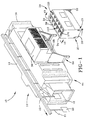
- a powder coating system 10 intended for use as a powder coating booth 12 for applying powder coating material on a production line basis, includes provision for automatic recovery and recirculation of the oversprayed powder in the system.
- the booth itself is of a generally conventional design and includes a canopy 14 having entry and exit vestibules 16 and 18, respectively, at each end thereof through which the article or part 20 to be coated can be transported.
- the article 20 to be coated is hung by a hook 21 from a conveyor system 22 to move slowly through the spray booth so that the part is sprayed with one or more spray guns through an opening (not shown) in the side of the canopy opposite the collector.
- a powder collector 24 as illustrated in FIGS. 1, 2 and 10 is mounted on wheels 26.
- the wheels 26 include leveling means 27, which are preferably vertically adjustable casters, to level the powder collector as required for the particular floor conditions.
- the collector during operation of system 10, is located adjacent an exhaust opening 28 in a side wall of canopy 14.
- the powder collector best shown in FIG. 10, has an inlet opening 30 in a side wall thereof with a seal 32, preferably "D" shaped in cross section thereabout.
- the inlet opening 30 is adapted to mate with canopy exhaust opening 28, as discussed below.
- a top plate 34 of the collector (See FIG. 1) has an exhaust opening 36 which fits under a fan plenum assembly 38 and is sealed against a bottom wall portion 40 of fan plenum 38, as illustrated in FIG. 9, disposed about an inlet opening 42, as discussed in more detail below.
- a principle feature of this invention is the construction of a base 44 which enables the canopy 14 to be automatically properly aligned with respect to the fan plenum assembly 38 so that a powder collector 24 can be moved into and out of position and quickly aligned and effectively sealed to both the exhaust opening 28 of powder spray canopy 14 and inlet opening 42 of the fan plenum 38.
- the base 44 as illustrated in FIG. 3, includes a rectangular table 46 having a central section 48 and opposite end sections 50 and 52 cantilevered outward from opposite ends of the central section 48.
- the table is supported on two substantially parallel beams 54 and 56 which extend transversely to the length of the table and have leg elements 58 at each end.
- Beams 54 and 56 which are positioned under the intersections of the central section 48 and the opposite end sections 50 and 52, are secured to the table by means such as welding.
- the triangular braces 60 secured to the bottom of the table and to the beams, provide additional support.
- the parallel beams 54 and 56 project outward from one side 62 of table 46 and form a base to which a fan support 64 (See FIG. 4) is secured.
- Leveling means 72 are provided on base 44 to simultaneously level the fan plenum assembly 38 and canopy 14, as discussed in more detail below.
- the leveling means includes vertically adjustable feet 72 at the bottom of legs 58.
- the fan support 64 has a front wall 80 with an opening 82 adapted to mate with the exhaust opening 28 (See FIG. 1) of canopy 14.
- a rectangular frame 84 around opening 82 provides a smooth surface against which the "D" shaped seal 32 of the powder collector is sealed, as discussed below.
- a plate 86, secured along the bottom edge of opening 82, is level with the table 46 which forms the inner floor of spray booth 12. Plate 86 extends into the inlet opening 30 of collector 24 so that any powder which builds up on the inner booth floor 46 can be easily swept into the collector.
- the fan support 64 includes two parallel side walls 88 and 90 secured to and extending substantially normal to front wall 80.
- the lower surfaces of the side walls are secured, by means such as welding or bolts, to the upper surface of the portions of the parallel beams 54 and 56 which project outward from side 62 of table 46.
- the upper surfaces of side walls 80 and 90 are perpendicular to the frame 84 and provide a support surface on which the bottom of the fan plenum assembly 38 can be attached by means such as nuts and bolts, as illustrated in FIG. 6.
- An important feature of this embodiment relates to the ability of the fan support 64 to maintain a perpendicular relationship between the opening 82 through the front wall 80 of fan support 64 and the inlet opening 42 of the fan plenum assembly 38. This relationship is critical to enable both the inlet opening 30 and the exhaust opening 36 of powder collector 24, which are perpendicular to one another, to be quickly and easily aligned with and properly sealed to both the opening 82 through the front wall 80 of fan support 64 and the inlet opening 42 of the fan plenum assembly 38.
- the inlet opening of fan plenum assembly 38 is securely mounted to the top surface of sidewalls 88 and 90, which in turn are perpendicular to the front wall 80, the inlet opening of fan plenum assembly 38 is automatically aligned to be perpendicular with the opening 82 in the side wall of fan support 64.
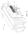
- the powder collector 24 can be rolled into position, as illustrated in FIG. 2, and simultaneously aligned with respect to the canopy and the fan plenum assembly so that an effective air tight seal can be achieved. That is, both inlet and exhaust openings 30 and 36, respectively, of powder collector 24 are located against fan support opening 82 and fan plenum inlet opening 42, respectively, so that an air tight seal can be quickly and easily achieved, as discussed in more detail below.
- An air tight seal is very important to the proper functioning of the powder coating system 10 because it enables more air entrained powder to be removed from powder coating booth 12, and prevents escape of the powder from the booth into the plant environment and from the collector into the fan plenum.
- Another aspect of the invention relates to the fan plenum assembly being supported by the base 44 instead of the canopy, as was often the case in the prior art.
- This enables the canopy to be constructed of a lightweight, non-metallic material, such as for example a plastic like polypropylene.
- a plastic canopy is that the powder coating material does not have an electrical attraction to the plastic and will not tend to stick to the sides of the canopy as with a metal canopy. This is particularly important when the color is changed and the system has to be cleaned before a new color of powder is sprayed.
- the canopy can be made of a translucent material which provides improved lighting inside the spray booth to better enable a system operator to monitor the system.
- the plastic is light weight which is more manageable to assemble and lower in cost.
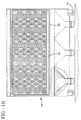
- FIG. 10 there is illustrated the front of powder collector 24 which has inlet opening 30.
- a seal means 32 typically comprising an elastomeric seal with a "D" shaped cross section, is disposed around inlet opening 30.
- conventional latches not shown, attached to fan support 64 pull collector 24 against the front wall 80 of fan support 64 and tightly compresses seal 32 against the frame 84 to form an air tight seal between the rear wall of the canopy and the inlet opening 30 of powder collector 24.
- a seal means 99 including a seal assembly 100 disposed about the inlet opening 42 in bottom 40 of the fan plenum assembly 38, as illustrated in FIGS. 7, 8 and 9.
- the seal assembly 100 includes a retractable, pneumatic seal member 102 secured in a bracket or extrusion 104.
- Extrusion 104 has an upper wall 105 which is secured to bottom wall 40 by any means such as spot welding.
- bracket side walls 106 and 108 extending downward from upper wall 105, converge inward toward each other and then turn outward to form oppositely disposed curved recesses 110 and 112 which grip the top edges of seal member 102.
- the seal member 102 is preferably constructed of an elastomeric material and has a normal deflated, retracted shape, the cross section of which is illustrated in FIG. 8, including an upper surface 114, two side walls 116 and 118 which project downward from the upper surface 114 and initially converge inward to form shoulders 120 and 122 and then diverge outward to form inwardly curved troughs and lower, outwardly rounded corners 124 and 126 which intersect at rib 128 having a jagged, outwardly facing surface 130.
- the seal member 102 also has a hollow inner chamber 132.
- seal member 102 is inflated with air into its expanded condition so that the hollow inner chamber forms a substantially circular cross section forcing rib 128 outward away from bottom surface 114. In this position, the surface 130 of rib 128 compresses against the top plate 34 of collector 24 and forms an air tight seal around powder collector exhaust opening 36 and fan plenum inlet opening 42.
- powder collector 24 can be moved in or out from under fan plenum 38 to replace the collector when a new color is being sprayed or the cartridge filters need replacing. That is, when the powder collector is rolled under the fan plenum assembly, the seal 102 is in the retracted position and does not interfere with the collector being moved into position.
- collector 24 is secured in place with a latch mechanism, as previously discussed, to provide an air tight seal between the rear wall of canopy 14 and the inlet opening 30 into powder collector 24.
- the seal assembly 100 is then inflated into the expanded position of FIG. 9 to compress seal 102 against the collector's upper plate 34 and form an air tight seal between exhaust opening 36 and air plenum inlet opening 42.
- the pneumatic seal exerts a downward force on collector 24 and thus additionally functions to secure the collector 24 in position.
- collector 24 is inadvertently unlatched, it is still secured with respect to the fan plenum because of the downward force from seal assembly 100.
- the seal is simply deflated and it contracts to its normal deflated condition, as illustrated in FIG. 8, so as not to interfere with the movement of the collector.
- a further advantage of inflatable seal 100 is that it can account to some degree for cases where the top of the collector 24 is not completely level with respect to the bottom of fan plenum 38. That is, even where these two components are not completely level with respect to one another, an effective seal will be made between collector 24 and fan plenum 38 by means of pneumatic seal 100, because pneumatic seal 100, being resilient, can correct to some degree for misalignment between collector 24 and fan plenum 38.
- pneumatic seal 100 being resilient, can correct to some degree for misalignment between collector 24 and fan plenum 38.
- This is yet another way in which the present invention facilitates the quick and easy leveling and sealing of collector 24 with respect to fan plenum 38 and booth canopy 14.
- the cartridge filters 120 include an elongated hollow member 124 formed of a filter media, such as a cylindrically shaped, filtering wall with a pleated outer surface and a hollow interior disposed about a longitudinal centerline 125.
- the cartridge filter 120 has a closed bottom end cap 126 with an internally threaded boss 128 secured to the bottom end thereof and an open top end cap 130 secured to the top end thereof.
- a tie rod 132 is threaded at both ends 134 and 136 and extends through the hollow interior of cartridge filter 120. Tie rod 132 is threadably engaged at end 134 to threaded boss 128 and at the opposite end 136 to support assembly 122. Between ends 134 and 136 is a handle 138 extending transverse to a centerline 140 through the tie rod. In the preferred embodiment, the handle is secured in a bore 142 through rod 132. The handle enables an assembler to easily rotate the tie rod and thread or unthread it from the boss 128.
- a roll pin 144 located near the threaded portion of end 136, extends transversely to centerline 140 through the tie rod and is preferably secured in and extends outward from both sides of a bore 146 through rod 132 (See FIGS. 12A & 12B).
- the roll pin 144 engages a slot 148 in a bushing 150 to prevent the rotation of tie rod 132 when the cartridge is being disassembled from the support 122, as discussed below.
- roll pin 144 is located adjacent the shoulder 152 formed at the intersection of the threaded and unthreaded sections of tie rod 132. While a single roll pin is illustrated, an additional roll pin can be installed in bore 153 if desired.
- a tie rod centering bracket 154 is formed of a circular plate 156 having a hole 158 through its center to freely receive the tie rod 132.
- a plurality of radial extending arms 159 are each attached at one end to the plate 156 and have an upstanding leg 160 at the other end.
- the radial arms 159 are spaced at substantially 90 degrees with respect to each other.
- the upstanding legs 160 abut against the inner surface of the cartridge and prevent radial movement of the bracket.
- the free ends of the legs are bent to form a stop 162 which rests against the top end 130 of the cartridge to hold bracket 154 in place.
- Bracket 154 functions to center the tie rod within filter 120.
- bracket 154 insures that the centerline 140 of the tie rod essentially coincides with the centerline 125 of cartridge 120. This alignment prevents the tie rod 132 from moving out of alignment with the centerline 125 of cartridge 120 during installation or removal of cartridge 120 which would tend to break the boss 128 or deform end cap 126.
- Support assembly 122 is adapted to support the filter cartridges 120 below openings 36a in the top plate 34 of powder collector 24 whereby the cartridge is secured with a tight seal against the bottom side 172 of top plate 34.
- Support assembly 122 includes a spider assembly 174 comprised of center bushing 150 and a plurality of truss arms 176, 178 and 180 affixed thereto and projecting radially outward at an angle of about 120 degrees with respect to each other.
- the outer ends of the truss arms are notched out so that an inner upstanding surface rests in a notch 181 extending radially outward from the periphery of opening 36a, as seen in FIG. 11, to prevent rotational or radial movement of spider 174.
- the radial extending surface of the notch in the truss arms rests on the top surface of plate 34 and supports the cartridge within powder collector 24.
- tie rod 140 is threaded into the internal threaded boss 128, centering bracket 154 is inserted onto the rod 140 in cartridge 120, and cartridge 120 is placed in the powder collector through the inlet opening 30.
- the perforated baffles shown in FIG. 10 are removed during this step so that the interior of collector 24 is completely open.
- Support assembly 122 is then secured across opening 36a.
- the assembler then reaches into the opening 36a through the top plate 34 and holding handle 138 pulls up cartridge 120 so that the upper threaded end of rod 132 passes through bushing 150, with roll pin 144 inserted into slot 148 of bushing 150.
- the assembler pulls up on handle 138 until seal 182 of cartridge 120 rests against the bottom surface 172 of plate 34.
- a nut 183 is threaded onto the upper threaded end of tie rod 132 and tightened to compress gasket 182 and seal cartridge 120 around inlet hole 36.
- the nut 183 When the cartridge is to be removed from the powder collector, the nut 183 is unthreaded. As the nut is turned in the counterclockwise direction to unthread it, roll pin 144 engages slot 148 in bushing 150 to prevent tie rod 132 from turning and being unthreaded from the threaded boss 128.
- a powder spray canopy is aligned with a fan plenum assembly by a fan support bracket which is itself supported by the base which supports the canopy so that a powder collector can be quickly aligned and effectively sealed to both the powder spray canopy and the fan assembly.
- a pneumatic seal is provided between the fan plenum and collector to facilitate this operation.
- a support assembly is provide for the filter cartridges which enables an assembler to easily and quickly install and remove the filter cartridge as needed from the powder collector.
Landscapes
- Details Or Accessories Of Spraying Plant Or Apparatus (AREA)
- Coating Apparatus (AREA)
- Electrostatic Spraying Apparatus (AREA)
Description
Claims (6)
- A powder coating apparatus (10) comprising a base (44), a fan plenum assembly (38) having an inlet opening (42) in a bottom wall (40) thereof, a canopy (14) of a powder spray booth (12) having an exhaust opening (28) in a side wall being secured to the base (44) and a powder collector (24) having an inlet opening (30) in a front wall and an exhaust opening (36) in a top plate, the powder collector (24) being adapted to be releasably sealed against the canopy (14) and the fan plenum assembly (38) whereby the exhaust opening (28) in the side wall of the canopy (14) is sealed with respect to the inlet opening (30) of the powder collector (24) and the inlet opening (42) of the fan plenum assembly (38) seals against the exhaust opening (36) of the powder collector (24) characterised in that the base (44) has secured thereto a fan support (64) which is adapted to support the fan plenum assembly (38).
- Apparatus according to claim 1 comprising means (72) for levelling the base (44).
- Apparatus according to claim 2 wherein the levelling means (72) simultaneously levels the fan plenum assembly (38) and the canopy (14).
- Apparatus according to claim 1,2 or 3 comprising means (27) for levelling the powder collector (24) with respect to the fan plenum assembly (38) and the canopy (14) whereby the inlet and exhaust openings (30,36) of the powder collector (24) are aligned for sealing with respect to the exhaust opening (28) of the canopy (14) and the inlet opening (42) of the fan plenum assembly (38), respectively.
- Apparatus according to any preceding claim comprising seal means (100) between the fan plenum assembly (38) and the powder collector (24) for sealing the exhaust opening (36) of the powder collector (24) against the inlet opening (42) of the fan plenum assembly (38).
- Apparatus according to claim 5 wherein the seal means (100) comprises a bracket (104) and pneumatic seal member (102) securely gripped therein.
Applications Claiming Priority (2)
| Application Number | Priority Date | Filing Date | Title |
|---|---|---|---|
| US95557492A | 1992-10-02 | 1992-10-02 | |
| US955574 | 1992-10-02 |
Publications (2)
| Publication Number | Publication Date |
|---|---|
| EP0645193A1 EP0645193A1 (en) | 1995-03-29 |
| EP0645193B1 true EP0645193B1 (en) | 1998-04-15 |
Family
ID=25497023
Family Applications (1)
| Application Number | Title | Priority Date | Filing Date |
|---|---|---|---|
| EP93307548A Expired - Lifetime EP0645193B1 (en) | 1992-10-02 | 1993-09-23 | Improvements in and relating powder coating apparatus |
Country Status (6)
| Country | Link |
|---|---|
| EP (1) | EP0645193B1 (en) |
| JP (1) | JPH06218317A (en) |
| CN (1) | CN1051256C (en) |
| CA (1) | CA2106029A1 (en) |
| CZ (1) | CZ205793A3 (en) |
| DE (1) | DE69318019T2 (en) |
Families Citing this family (5)
| Publication number | Priority date | Publication date | Assignee | Title |
|---|---|---|---|---|
| DE102007040896B4 (en) * | 2007-08-24 | 2023-02-16 | Dürr Systems Ag | Device for separating wet paint overspray, installation for painting objects, method for producing a device for separating wet paint overspray and method for converting an existing device for separating wet paint overspray |
| ES2561046T3 (en) | 2008-12-19 | 2016-02-24 | Dürr Systems GmbH | Paint installation and procedure for the operation of a paint installation |
| EP2995361B1 (en) * | 2010-06-18 | 2023-04-19 | Airex Co., Ltd. | Filter unit |
| CN103657929A (en) * | 2012-09-21 | 2014-03-26 | 招远泽洋工具制造有限公司 | Four-side rotary type powder returning device |
| CN114798288B (en) * | 2022-05-23 | 2022-12-30 | 浙江明泉工业装备科技有限公司 | Based on functional intelligent coating line spraying firing equipment of robot |
Family Cites Families (3)
| Publication number | Priority date | Publication date | Assignee | Title |
|---|---|---|---|---|
| US4498913A (en) * | 1983-10-06 | 1985-02-12 | Nordson Corporation | Apparatus for filtering air for a powder spray booth |
| US4662309A (en) * | 1986-04-22 | 1987-05-05 | Nordson Corporation | Portable powder spray booth |
| DE9207787U1 (en) * | 1992-06-10 | 1992-09-17 | Hestermann, Gerhard, 7990 Friedrichshafen, De |
-
1993
- 1993-09-13 CA CA002106029A patent/CA2106029A1/en not_active Abandoned
- 1993-09-23 EP EP93307548A patent/EP0645193B1/en not_active Expired - Lifetime
- 1993-09-23 DE DE69318019T patent/DE69318019T2/en not_active Expired - Fee Related
- 1993-09-29 CN CN93118313A patent/CN1051256C/en not_active Expired - Fee Related
- 1993-10-01 CZ CZ932057A patent/CZ205793A3/en unknown
- 1993-10-01 JP JP5246677A patent/JPH06218317A/en active Pending
Also Published As
| Publication number | Publication date |
|---|---|
| JPH06218317A (en) | 1994-08-09 |
| CA2106029A1 (en) | 1994-04-03 |
| CZ205793A3 (en) | 1995-02-15 |
| EP0645193A1 (en) | 1995-03-29 |
| DE69318019D1 (en) | 1998-05-20 |
| DE69318019T2 (en) | 1998-08-06 |
| CN1051256C (en) | 2000-04-12 |
| CN1085130A (en) | 1994-04-13 |
Similar Documents
| Publication | Publication Date | Title |
|---|---|---|
| JP3234597B2 (en) | Powder coating system | |
| US4823731A (en) | Multiple filter/cyclone air filtration apparatus with single, movable filter cleaning system | |
| US4257790A (en) | Quick change filter bag arrangement | |
| US5224974A (en) | Filter for use in dry powder spray coating systems | |
| EP0974400B1 (en) | Powder coating system | |
| US4277260A (en) | Powder collectors | |
| JP2810132B2 (en) | Cartridge mounting device for powder collector | |
| US7074274B1 (en) | Quick color change powder coating system | |
| US5261934A (en) | Powder collection method and apparatus with isolated filter pulsing and compression mounted cartridges | |
| US20060137315A1 (en) | Controlling cyclone efficiency with vacuum interface | |
| US4498913A (en) | Apparatus for filtering air for a powder spray booth | |
| JPH0824865B2 (en) | Portable type powder spraying and recovery device | |
| JP2537844B2 (en) | Powder boots | |
| EP0645193B1 (en) | Improvements in and relating powder coating apparatus | |
| US20130042805A1 (en) | Powder coating booth with tangential exhaust duct | |
| US3777706A (en) | Spray booth and system | |
| US7014670B2 (en) | Controlling cyclone efficiency with a vacuum interface | |
| US5700323A (en) | Anti-contamination valve for powder delivery system | |
| US5851248A (en) | Filter cartridge assembly for powder coating booth and collection system | |
| NZ212311A (en) | Powder recovery apparatus with secondary cyclone and sieve mounted at side of main cyclone | |
| US4928624A (en) | Powder spray booth with overspray collection system | |
| US6432173B1 (en) | Centrifugal separator arrangement for powder coating recovery system and methods | |
| US5421846A (en) | Air filtration apparatus for the control of industrial air pollution | |
| US5549723A (en) | Filter cap | |
| US5103760A (en) | Liquid to powder spray booth conversion insert |
Legal Events
| Date | Code | Title | Description |
|---|---|---|---|
| PUAI | Public reference made under article 153(3) epc to a published international application that has entered the european phase |
Free format text: ORIGINAL CODE: 0009012 |
|
| AK | Designated contracting states |
Kind code of ref document: A1 Designated state(s): CH DE FR GB IT LI |
|
| 17P | Request for examination filed |
Effective date: 19950914 |
|
| 17Q | First examination report despatched |
Effective date: 19960611 |
|
| GRAG | Despatch of communication of intention to grant |
Free format text: ORIGINAL CODE: EPIDOS AGRA |
|
| GRAG | Despatch of communication of intention to grant |
Free format text: ORIGINAL CODE: EPIDOS AGRA |
|
| GRAH | Despatch of communication of intention to grant a patent |
Free format text: ORIGINAL CODE: EPIDOS IGRA |
|
| GRAH | Despatch of communication of intention to grant a patent |
Free format text: ORIGINAL CODE: EPIDOS IGRA |
|
| GRAA | (expected) grant |
Free format text: ORIGINAL CODE: 0009210 |
|
| AK | Designated contracting states |
Kind code of ref document: B1 Designated state(s): CH DE FR GB IT LI |
|
| REG | Reference to a national code |
Ref country code: CH Ref legal event code: NV Representative=s name: BRAUN & PARTNER PATENT-, MARKEN-, RECHTSANWAELTE Ref country code: CH Ref legal event code: EP |
|
| REF | Corresponds to: |
Ref document number: 69318019 Country of ref document: DE Date of ref document: 19980520 |
|
| ET | Fr: translation filed | ||
| ITF | It: translation for a ep patent filed |
Owner name: MODIANO & ASSOCIATI S.R.L. |
|
| PLBE | No opposition filed within time limit |
Free format text: ORIGINAL CODE: 0009261 |
|
| STAA | Information on the status of an ep patent application or granted ep patent |
Free format text: STATUS: NO OPPOSITION FILED WITHIN TIME LIMIT |
|
| 26N | No opposition filed | ||
| PGFP | Annual fee paid to national office [announced via postgrant information from national office to epo] |
Ref country code: FR Payment date: 20010817 Year of fee payment: 9 |
|
| PGFP | Annual fee paid to national office [announced via postgrant information from national office to epo] |
Ref country code: GB Payment date: 20010820 Year of fee payment: 9 Ref country code: DE Payment date: 20010820 Year of fee payment: 9 |
|
| PGFP | Annual fee paid to national office [announced via postgrant information from national office to epo] |
Ref country code: CH Payment date: 20010827 Year of fee payment: 9 |
|
| REG | Reference to a national code |
Ref country code: GB Ref legal event code: IF02 |
|
| PG25 | Lapsed in a contracting state [announced via postgrant information from national office to epo] |
Ref country code: GB Free format text: LAPSE BECAUSE OF NON-PAYMENT OF DUE FEES Effective date: 20020923 |
|
| PG25 | Lapsed in a contracting state [announced via postgrant information from national office to epo] |
Ref country code: LI Free format text: LAPSE BECAUSE OF NON-PAYMENT OF DUE FEES Effective date: 20020930 Ref country code: CH Free format text: LAPSE BECAUSE OF NON-PAYMENT OF DUE FEES Effective date: 20020930 |
|
| PG25 | Lapsed in a contracting state [announced via postgrant information from national office to epo] |
Ref country code: DE Free format text: LAPSE BECAUSE OF NON-PAYMENT OF DUE FEES Effective date: 20030401 |
|
| GBPC | Gb: european patent ceased through non-payment of renewal fee |
Effective date: 20020923 |
|
| REG | Reference to a national code |
Ref country code: CH Ref legal event code: PL |
|
| PG25 | Lapsed in a contracting state [announced via postgrant information from national office to epo] |
Ref country code: FR Free format text: LAPSE BECAUSE OF NON-PAYMENT OF DUE FEES Effective date: 20030603 |
|
| REG | Reference to a national code |
Ref country code: FR Ref legal event code: ST |
|
| PG25 | Lapsed in a contracting state [announced via postgrant information from national office to epo] |
Ref country code: IT Free format text: LAPSE BECAUSE OF NON-PAYMENT OF DUE FEES;WARNING: LAPSES OF ITALIAN PATENTS WITH EFFECTIVE DATE BEFORE 2007 MAY HAVE OCCURRED AT ANY TIME BEFORE 2007. THE CORRECT EFFECTIVE DATE MAY BE DIFFERENT FROM THE ONE RECORDED. Effective date: 20050923 |