EP0643324A2 - Photographic processing apparatus - Google Patents
Photographic processing apparatus Download PDFInfo
- Publication number
- EP0643324A2 EP0643324A2 EP94113952A EP94113952A EP0643324A2 EP 0643324 A2 EP0643324 A2 EP 0643324A2 EP 94113952 A EP94113952 A EP 94113952A EP 94113952 A EP94113952 A EP 94113952A EP 0643324 A2 EP0643324 A2 EP 0643324A2
- Authority
- EP
- European Patent Office
- Prior art keywords
- film
- negative mask
- exposure
- unit
- sensors
- Prior art date
- Legal status (The legal status is an assumption and is not a legal conclusion. Google has not performed a legal analysis and makes no representation as to the accuracy of the status listed.)
- Granted
Links
Images


Classifications
-
- G—PHYSICS
- G03—PHOTOGRAPHY; CINEMATOGRAPHY; ANALOGOUS TECHNIQUES USING WAVES OTHER THAN OPTICAL WAVES; ELECTROGRAPHY; HOLOGRAPHY
- G03B—APPARATUS OR ARRANGEMENTS FOR TAKING PHOTOGRAPHS OR FOR PROJECTING OR VIEWING THEM; APPARATUS OR ARRANGEMENTS EMPLOYING ANALOGOUS TECHNIQUES USING WAVES OTHER THAN OPTICAL WAVES; ACCESSORIES THEREFOR
- G03B27/00—Photographic printing apparatus
- G03B27/32—Projection printing apparatus, e.g. enlarger, copying camera
- G03B27/52—Details
- G03B27/62—Holders for the original
- G03B27/6271—Holders for the original in enlargers
- G03B27/6285—Handling strips
-
- G—PHYSICS
- G03—PHOTOGRAPHY; CINEMATOGRAPHY; ANALOGOUS TECHNIQUES USING WAVES OTHER THAN OPTICAL WAVES; ELECTROGRAPHY; HOLOGRAPHY
- G03B—APPARATUS OR ARRANGEMENTS FOR TAKING PHOTOGRAPHS OR FOR PROJECTING OR VIEWING THEM; APPARATUS OR ARRANGEMENTS EMPLOYING ANALOGOUS TECHNIQUES USING WAVES OTHER THAN OPTICAL WAVES; ACCESSORIES THEREFOR
- G03B27/00—Photographic printing apparatus
- G03B27/32—Projection printing apparatus, e.g. enlarger, copying camera
- G03B27/46—Projection printing apparatus, e.g. enlarger, copying camera for automatic sequential copying of different originals, e.g. enlargers, roll film printers
-
- G—PHYSICS
- G03—PHOTOGRAPHY; CINEMATOGRAPHY; ANALOGOUS TECHNIQUES USING WAVES OTHER THAN OPTICAL WAVES; ELECTROGRAPHY; HOLOGRAPHY
- G03B—APPARATUS OR ARRANGEMENTS FOR TAKING PHOTOGRAPHS OR FOR PROJECTING OR VIEWING THEM; APPARATUS OR ARRANGEMENTS EMPLOYING ANALOGOUS TECHNIQUES USING WAVES OTHER THAN OPTICAL WAVES; ACCESSORIES THEREFOR
- G03B27/00—Photographic printing apparatus
- G03B27/32—Projection printing apparatus, e.g. enlarger, copying camera
Definitions
- This invention relates to a photographic processing apparatus in which a film is developed and dried, images on the film are printed on photographic paper, and the photographic paper is developed.
- a photographic processing apparatus in which a series of operations including the development and drying of film, printing on photographic paper and development thereof are automatically carried out.
- a negative mask having a film guide path is provided in the exposure unit.
- the images are printed on the photographic paper by emitting the light to a film supported by the negative mask.
- the film guide path has one common size and the negative mask is fixedly supported in the exposure unit. Thus, it was possible to process the film of only one size.
- a photographic processing apparatus having a film developing unit, a drying unit, an exposure unit to which a film developed and dried is fed, and a photographic paper developing unit, the exposure unit having a negative mask having a film guide path, the film being fed along the film guide path and illuminated by the light to print film images on the film to photographic paper, which is fed to the photographic paper developing unit for development, characterized in that the plurality of film guide paths are provided in parallel to one another in the negative mask for different widths of films, that a transfer means for transferring the negative mask is provided to bring one of the film guide paths into alignment with an exposure axis, that a plurality of sensors are provided along a film feed path toward the negative mask to detect the width of the film, so that the film guide path selected based on the signal from the sensors for the film having a detected width will be aligned with the exposure axis.
- the width of the film is detected by the sensors.
- a film guide path is selected to the detected film size.
- the position of the negative mask is adjusted so that the selected film guide path will be aligned with the exposure axis.
- the printing is carried out by feeding the film thereto.
- a plurality of film guide paths each corresponding to the film size are provided in the negative mask in the exposure unit.
- the negative mask is moved according to the width of the film fed therein until the film guide path corresponding to the film size is aligned with the exposure axis.
- Fig. 1 is a schematic view of a photographic processing apparatus according to the present invention.
- Fig. 6 shows a film F processed by this photographic processing apparatus.
- the film F is connected to a flexible leader L which is formed with a plurality of perforations a at regular intervals.
- the film F led by the leader L, is fed to a plurality of treating tanks T0 containing different treating solutions in a developing unit 1. After developed, the film F is dried in a drying unit 2 next to the developing unit 1. Thereafter, the film F is fed into a film stocking unit 3.
- the film stocking unit 3 has a plurality of pairs of feed rollers 4 arranged in line.
- the leader L and the film F are carried in one direction by the rotation of the feed rollers 4. If the preceding portion of the film F stagnates in the film stocking unit 3, a loop L O is created between the feed rollers 4 so as to stop the feed of the film F until the preceding portion of the film F is fed out.
- a turn roller 5 Along a film path in the film stocking unit 3 are provided a turn roller 5 and first to third press rollers 6a to 6c mounted around the turn roller 5.
- film sensors 7 to detect perforations of the film F.
- a cutter 8 and a pair of feed rollers 9a and 9b are provided ahead of the film sensors 7.
- the cutter 8 is actuated to cut the film F apart from the leader L.
- the leader L, now cut off from the film F, is removed from the film path by the feed rollers 9a and 9b.
- the turn roller 5 While the film F is being cut from the leader, the turn roller 5 is stopped. After the film F has been cut off, it will be rotated in a reverse direction to feed the film F in an opposite direction for a predetermined length.
- a film guide 10 is provided under the turn roller 5. After the film F has been fed in an opposite direction, the film guide 10 will be pivoted around an axis 10a toward the turn roller 5 actuated by a pivot mechanism (not shown) so as to press the leading end of the film F against the circumference of the turn roller 5.
- the turn roller 5 With the film F pressed against the turn roller 5, the turn roller 5 will rotate in the original direction (shown by arrow in Fig. 3) to feed the film F to an exposure unit 11 next to the film stocking unit 3.
- a light source 12 As shown in Fig. 1, in the exposure unit 11, the light from a light source 12 is thrown to the film F reflected by mirrors 13a and 13b.
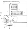
- the images on the film F are enlarged by a printing lens 14 to print them on photographic paper P drawn onto an exposure table 15 (Fig. 2).
- X designates an exposure axis.
- the photographic paper P in the form of a roll is accommodated in a magazine 16 and drawn onto the exposure table 15.
- the printed photographic paper P is further fed through a plurality of treating tanks T1 containing different treating solutions. In this manner, the photographic paper P is developed.
- a negative mask 18 is provided in the exposure unit 11 to guide the film F fed from the turn roller 5 onto the exposure axis X.
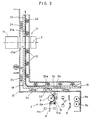
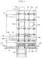
- Figs. 3 and 4 show in detail the negative mask 18 which is L-shaped and comprises a horizontal portion 19 and a vertical portion 20 joined together. Inside the negative mask 18 are parallely arranged a first film guide path 21a and a second film guide path 21b having different widths from each other. A plurality of pairs of rollers 22 are provided for both of the film guide paths 21a and 21b.
- the horizontal portion 19 of the negative mask 18 is formed at its bottom with film holes 30a and 30b along the film guide paths 21a and 21b, respectively.
- the vertical portion 20 of the negative mask 18 is formed with exposure windows 23a and 23b along the film guide paths 21a and 21b, respectively.
- the negative mask 18 is supported so as to be movable in a direction perpendicular to the feed direction of the film F along a plurality of rails 24 mounted in parallel to one another.
- the negative mask 18 is moved by a transfer unit 25 (Fig. 4) until one of the film holes 30a and 30b is in alignment with a film outlet 32 formed in a case 31 and until one of the exposure windows 23a and 23b is aligned with the exposure axis X.
- the transfer unit 25 may be of any arrangement. In this embodiment, it comprises a pair of geared pulleys 26a and 26b and a timing belt 27 provided therearound. As shown in Fig. 4, part of the timing belt 27 is coupled to the negative mask 18 so that one of the geared pulleys 26a and 26b is driven by a motor 28 to move the negative mask 18.
- Switches LS1 and LS2 are provided at both ends of the path of the negative mask 18 in order to stop one of the first and second film guide paths 21a and 21b on the exposure axis X.
- the switch LS1 or LS2 When the switch LS1 or LS2 is turned on, the motor 28 will stop.
- a photo-sensor may be provided in place of these switches to control the stop position of the negative mask 18.
- the motor 28 is activated in response to the detecting signals supplied from film-size detecting sensors PH provided along the film feed path in the film stocking unit 3.
- the width of the first film guide path 21a corresponds to A-film F1 whereas the width of the second film guide path 21b to B-film F2.
- A-film F1 is supplied to the first film guide path 21a from the film outlet 32 through the film hole 30a.
- A-film F1 is stopped to print it on the photographic paper P which has been drawn on the exposure table 15.
- A-film F1 is intermittently fed with its pitch defined by one frame. Every time A-film F1 stops, the film image thereof is printed on the photographic paper P intermittently moved for a predetermined stroke in one direction.
- A-film F1 is entirely fed to the first film guide path 21a
- the next film is fed to the feed rollers 9a and 9b from between the turn roller 5 and the first press roller 6a.
- the film guide 10 is away from the turn roller 5.
- the next film F i.e. B-film F2
- the motor 28 will be activated to move the negative mask 18 along the rails 24 to align the exposure window 23b formed in the second film guide path 21b with the exposure axis X.
- B-film F2 is fed to the second film guide path 21b and printing is carried out.
- two film guide paths i.e. the first and second film guide paths 21a and 21b are provided in the negative mask 18, but their number is not limited thereto.
Abstract
Description
- This invention relates to a photographic processing apparatus in which a film is developed and dried, images on the film are printed on photographic paper, and the photographic paper is developed.
- A photographic processing apparatus is known in which a series of operations including the development and drying of film, printing on photographic paper and development thereof are automatically carried out.
- In such a photographic processing apparatus as mentioned above, a negative mask having a film guide path is provided in the exposure unit. The images are printed on the photographic paper by emitting the light to a film supported by the negative mask.
- In such a conventional photographic processing apparatus, the film guide path has one common size and the negative mask is fixedly supported in the exposure unit. Thus, it was possible to process the film of only one size.
- It is an object of the present invention to provide a photographic processing apparatus which can process films of different widths.
- In order to solve the abovesaid problems, in the present invention, there is provided a photographic processing apparatus having a film developing unit, a drying unit, an exposure unit to which a film developed and dried is fed, and a photographic paper developing unit, the exposure unit having a negative mask having a film guide path, the film being fed along the film guide path and illuminated by the light to print film images on the film to photographic paper, which is fed to the photographic paper developing unit for development, characterized in that the plurality of film guide paths are provided in parallel to one another in the negative mask for different widths of films, that a transfer means for transferring the negative mask is provided to bring one of the film guide paths into alignment with an exposure axis, that a plurality of sensors are provided along a film feed path toward the negative mask to detect the width of the film, so that the film guide path selected based on the signal from the sensors for the film having a detected width will be aligned with the exposure axis.
- With this photographic processing apparatus, the width of the film is detected by the sensors. A film guide path is selected to the detected film size. The position of the negative mask is adjusted so that the selected film guide path will be aligned with the exposure axis. The printing is carried out by feeding the film thereto.
- As described above, with this photographic processing apparatus according to the present invention, a plurality of film guide paths each corresponding to the film size are provided in the negative mask in the exposure unit. The negative mask is moved according to the width of the film fed therein until the film guide path corresponding to the film size is aligned with the exposure axis. Thus, the films of different sizes can be printed in one photographic processing apparatus.
- Other features and objects of the present invention will become apparent from the following description made with reference to the accompanying drawings, in which:
- Fig. 1 is a schematic view showing a portion of the photographic processing apparatus according to this invention from the film developing unit to the exposure unit;
- Fig. 2 is a schematic view showing the film developing unit and the exposure unit of the same;
- Fig. 3 is a vertical sectional front view of the negative mask of the same;
- Fig. 4 is a partially cutaway sectional side view of Fig. 3;
- Fig. 5 is a schematic plan view of the exposure unit of the same;
- Fig. 6 is a perspective view showing the leader and the film; and
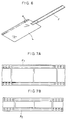
- Figs. 7A and 7B are front views each showing one portion of the film having a different width from another
- Now we shall explain the embodiment in this invention with reference to the accompanying drawings.
- Fig. 1 is a schematic view of a photographic processing apparatus according to the present invention. Fig. 6 shows a film F processed by this photographic processing apparatus. The film F is connected to a flexible leader L which is formed with a plurality of perforations a at regular intervals.
- As shown in Fig. 1, the film F, led by the leader L, is fed to a plurality of treating tanks T₀ containing different treating solutions in a developing
unit 1. After developed, the film F is dried in adrying unit 2 next to the developingunit 1. Thereafter, the film F is fed into afilm stocking unit 3. - The
film stocking unit 3 has a plurality of pairs offeed rollers 4 arranged in line. The leader L and the film F are carried in one direction by the rotation of thefeed rollers 4. If the preceding portion of the film F stagnates in thefilm stocking unit 3, a loop LO is created between thefeed rollers 4 so as to stop the feed of the film F until the preceding portion of the film F is fed out. - Along a film path in the
film stocking unit 3 are provided aturn roller 5 and first tothird press rollers 6a to 6c mounted around theturn roller 5. - As shown in Fig. 3, in front of the
turn roller 5 are mountedfilm sensors 7 to detect perforations of the film F. Acutter 8 and a pair offeed rollers film sensors 7. When thefilm sensors 7 detect the perforations of the film F, thecutter 8 is actuated to cut the film F apart from the leader L. The leader L, now cut off from the film F, is removed from the film path by thefeed rollers - While the film F is being cut from the leader, the
turn roller 5 is stopped. After the film F has been cut off, it will be rotated in a reverse direction to feed the film F in an opposite direction for a predetermined length. - A
film guide 10 is provided under theturn roller 5. After the film F has been fed in an opposite direction, thefilm guide 10 will be pivoted around an axis 10a toward theturn roller 5 actuated by a pivot mechanism (not shown) so as to press the leading end of the film F against the circumference of theturn roller 5. - With the film F pressed against the
turn roller 5, theturn roller 5 will rotate in the original direction (shown by arrow in Fig. 3) to feed the film F to anexposure unit 11 next to thefilm stocking unit 3. - As shown in Fig. 1, in the
exposure unit 11, the light from alight source 12 is thrown to the film F reflected bymirrors printing lens 14 to print them on photographic paper P drawn onto an exposure table 15 (Fig. 2). In the figure, X designates an exposure axis. - The photographic paper P in the form of a roll is accommodated in a
magazine 16 and drawn onto the exposure table 15. The printed photographic paper P is further fed through a plurality of treating tanks T₁ containing different treating solutions. In this manner, the photographic paper P is developed. - As shown in Fig. 1, a
negative mask 18 is provided in theexposure unit 11 to guide the film F fed from theturn roller 5 onto the exposure axis X. - Figs. 3 and 4 show in detail the
negative mask 18 which is L-shaped and comprises ahorizontal portion 19 and avertical portion 20 joined together. Inside thenegative mask 18 are parallely arranged a firstfilm guide path 21a and a secondfilm guide path 21b having different widths from each other. A plurality of pairs ofrollers 22 are provided for both of thefilm guide paths - The
horizontal portion 19 of thenegative mask 18 is formed at its bottom withfilm holes film guide paths - Also, the
vertical portion 20 of thenegative mask 18 is formed withexposure windows film guide paths - The
negative mask 18 is supported so as to be movable in a direction perpendicular to the feed direction of the film F along a plurality ofrails 24 mounted in parallel to one another. Thenegative mask 18 is moved by a transfer unit 25 (Fig. 4) until one of thefilm holes film outlet 32 formed in acase 31 and until one of theexposure windows - The
transfer unit 25 may be of any arrangement. In this embodiment, it comprises a pair of gearedpulleys 26a and 26b and atiming belt 27 provided therearound. As shown in Fig. 4, part of thetiming belt 27 is coupled to thenegative mask 18 so that one of the gearedpulleys 26a and 26b is driven by amotor 28 to move thenegative mask 18. - Switches LS1 and LS2 are provided at both ends of the path of the
negative mask 18 in order to stop one of the first and secondfilm guide paths motor 28 will stop. Alternatively, a photo-sensor may be provided in place of these switches to control the stop position of thenegative mask 18. - The
motor 28 is activated in response to the detecting signals supplied from film-size detecting sensors PH provided along the film feed path in thefilm stocking unit 3. - Let us assume that, of the films shown in Figs. 7A and 7B, the one having a larger width is A-film F1 and the other one is B-film F2. Accordingly, the width of the first
film guide path 21a corresponds to A-film F1 whereas the width of the secondfilm guide path 21b to B-film F2. - In this state, supposing that the leader L connected to A-film F1 is fed to the
film stocking unit 3 whereas A-film F1 is cut off from the leader L by thecutter 8; when the film-size detecting sensors PH detect that the film is A-film F1, themotor 28 shown in Fig. 4 is activated to move thenegative mask 18 along therails 24. When theexposure window 23a formed in the firstfilm guide path 21a is aligned with the exposure axis X, themotor 28 will stop, and thenegative mask 18 keep its position with theexposure window 23a aligned with the exposure axis X. - After the position of the
negative mask 18 has been adjusted, A-film F1 is supplied to the firstfilm guide path 21a from thefilm outlet 32 through thefilm hole 30a. When the first image frame exactly matches theexposure window 23a, A-film F1 is stopped to print it on the photographic paper P which has been drawn on the exposure table 15. Thereafter, A-film F1 is intermittently fed with its pitch defined by one frame. Every time A-film F1 stops, the film image thereof is printed on the photographic paper P intermittently moved for a predetermined stroke in one direction. - When A-film F1 is entirely fed to the first
film guide path 21a, the next film is fed to thefeed rollers turn roller 5 and thefirst press roller 6a. In this state, thefilm guide 10 is away from theturn roller 5. The next film F, i.e. B-film F2, is then cut off from the leader L by thecutter 8 and detected by the film-size detecting sensors PH. After A-film F1 has been discharged from the firstfilm guide path 21a, themotor 28 will be activated to move thenegative mask 18 along therails 24 to align theexposure window 23b formed in the secondfilm guide path 21b with the exposure axis X. - After the position of the
negative mask 18 has been adjusted, B-film F2 is fed to the secondfilm guide path 21b and printing is carried out. - In the embodiment, two film guide paths, i.e. the first and second
film guide paths negative mask 18, but their number is not limited thereto.
Claims (1)
- A photographic processing apparatus having a film developing unit, a drying unit, an exposure unit to which a film developed and dried is fed, and a photographic paper developing unit, said exposure unit having a negative mask having a film guide path, said film being fed along said film guide path and illuminated by the light to print images on said film to photographic paper, which is fed to said photographic paper developing unit for development, characterized in that a plurality of said film guide paths are provided in parallel to one another in said negative mask for different widths of films, that a transfer means for transferring said negative mask is provided to bring one of said film guide paths into alignment with an exposure axis, that a plurality of sensors are provided along a film feed path toward said negative mask to detect the width of the film, so that said film guide path selected based on the signal from said sensors for the film having a detected width will be aligned with said exposure axis.
Applications Claiming Priority (2)
| Application Number | Priority Date | Filing Date | Title |
|---|---|---|---|
| JP223483/93 | 1993-09-08 | ||
| JP5223483A JP2783129B2 (en) | 1993-09-08 | 1993-09-08 | Photo processing equipment |
Publications (3)
| Publication Number | Publication Date |
|---|---|
| EP0643324A2 true EP0643324A2 (en) | 1995-03-15 |
| EP0643324A3 EP0643324A3 (en) | 1995-08-16 |
| EP0643324B1 EP0643324B1 (en) | 1998-12-16 |
Family
ID=16798846
Family Applications (1)
| Application Number | Title | Priority Date | Filing Date |
|---|---|---|---|
| EP94113952A Expired - Lifetime EP0643324B1 (en) | 1993-09-08 | 1994-09-06 | Photographic processing apparatus |
Country Status (7)
| Country | Link |
|---|---|
| US (1) | US5444514A (en) |
| EP (1) | EP0643324B1 (en) |
| JP (1) | JP2783129B2 (en) |
| KR (1) | KR0178288B1 (en) |
| CN (1) | CN1036027C (en) |
| CA (1) | CA2130848C (en) |
| DE (1) | DE69415245T2 (en) |
Families Citing this family (7)
| Publication number | Priority date | Publication date | Assignee | Title |
|---|---|---|---|---|
| US5814788A (en) * | 1995-09-14 | 1998-09-29 | Illinois Tool Works Inc. | Method and apparatus for electronic control of the output of an engine driven, chopped DC welding power supply, driven by an AC generator |
| JPH09270897A (en) * | 1996-04-02 | 1997-10-14 | Canon Inc | Image reader |
| EP0935160B1 (en) * | 1998-02-04 | 2002-10-02 | Imip Llc | Photoelectric scanning device and photographic printing apparatus incorporating it |
| DE19841071A1 (en) * | 1998-09-09 | 2000-03-16 | Eastman Kodak Co | Movie deck |
| JP2001318438A (en) * | 2000-05-10 | 2001-11-16 | Minolta Co Ltd | Negative carrier and film scanner having the same |
| US9499649B2 (en) * | 2007-12-21 | 2016-11-22 | Rolic Ag | Functionalized photoreactive compounds |
| KR101291703B1 (en) * | 2012-12-04 | 2013-07-31 | 주식회사 남영기계 | Flexible printed circuit substrate for the production of roll-to-roll winder device |
Citations (4)
| Publication number | Priority date | Publication date | Assignee | Title |
|---|---|---|---|---|
| EP0136979A2 (en) * | 1983-09-30 | 1985-04-10 | GRETAG Aktiengesellschaft | Laboratory arrangement for producing photographic copies |
| JPS60149039A (en) * | 1984-01-14 | 1985-08-06 | Fuji Photo Optical Co Ltd | Negative mask |
| JPS60149040A (en) * | 1984-01-14 | 1985-08-06 | Fuji Photo Optical Co Ltd | Negative carrier |
| DE3908522A1 (en) * | 1988-03-16 | 1989-10-05 | Fuji Photo Film Co Ltd | PHOTOGRAPHIC COPIER WITH A MONITOR |
Family Cites Families (7)
| Publication number | Priority date | Publication date | Assignee | Title |
|---|---|---|---|---|
| US4185912A (en) * | 1977-06-27 | 1980-01-29 | Theodore F. Schwartz | Photographic developer and printer |
| US4783686A (en) * | 1986-05-21 | 1988-11-08 | Minolta Camera Kabushiki Kaisha | Microcamera |
| FR2616925B1 (en) * | 1987-06-16 | 1989-09-08 | Crasnianski Serge | INTEGRATED AUTOMATIC DEVICE FOR THE DEVELOPMENT OF PHOTOGRAPHIC FILMS AND THE DRAWING AND DEVELOPMENT OF CONTINUOUS PHOTOGRAPHS |
| US4996555A (en) * | 1989-01-13 | 1991-02-26 | Fuji Photo Film Co., Ltd. | Optical system for use with a viewfinder |
| JP2511532B2 (en) * | 1989-08-18 | 1996-06-26 | 富士写真フイルム株式会社 | Photo printing equipment |
| JP2602583B2 (en) * | 1990-12-25 | 1997-04-23 | 富士写真フイルム株式会社 | Photo printer |
| DE4126578C2 (en) * | 1991-08-12 | 1996-12-12 | Agfa Gevaert Ag | Device for copying photographic recordings |
-
1993
- 1993-09-08 JP JP5223483A patent/JP2783129B2/en not_active Expired - Fee Related
-
1994
- 1994-08-25 CA CA002130848A patent/CA2130848C/en not_active Expired - Fee Related
- 1994-09-01 KR KR1019940022012A patent/KR0178288B1/en not_active IP Right Cessation
- 1994-09-05 CN CN94109153A patent/CN1036027C/en not_active Expired - Fee Related
- 1994-09-06 DE DE69415245T patent/DE69415245T2/en not_active Expired - Fee Related
- 1994-09-06 US US08/301,010 patent/US5444514A/en not_active Expired - Lifetime
- 1994-09-06 EP EP94113952A patent/EP0643324B1/en not_active Expired - Lifetime
Patent Citations (4)
| Publication number | Priority date | Publication date | Assignee | Title |
|---|---|---|---|---|
| EP0136979A2 (en) * | 1983-09-30 | 1985-04-10 | GRETAG Aktiengesellschaft | Laboratory arrangement for producing photographic copies |
| JPS60149039A (en) * | 1984-01-14 | 1985-08-06 | Fuji Photo Optical Co Ltd | Negative mask |
| JPS60149040A (en) * | 1984-01-14 | 1985-08-06 | Fuji Photo Optical Co Ltd | Negative carrier |
| DE3908522A1 (en) * | 1988-03-16 | 1989-10-05 | Fuji Photo Film Co Ltd | PHOTOGRAPHIC COPIER WITH A MONITOR |
Non-Patent Citations (2)
| Title |
|---|
| PATENT ABSTRACTS OF JAPAN vol. 009 no. 323 (P-414) ,18 December 1985 & JP-A-60 149039 (FUJI SHASHIN KOKI KK) 6 August 1985, * |
| PATENT ABSTRACTS OF JAPAN vol. 009 no. 323 (P-414) ,18 December 1985 & JP-A-60 149040 (FUJI SHASHIN KOKI KK) 6 August 1985, * |
Also Published As
| Publication number | Publication date |
|---|---|
| US5444514A (en) | 1995-08-22 |
| KR950009356A (en) | 1995-04-21 |
| JPH0777744A (en) | 1995-03-20 |
| DE69415245T2 (en) | 1999-05-20 |
| DE69415245D1 (en) | 1999-01-28 |
| EP0643324B1 (en) | 1998-12-16 |
| KR0178288B1 (en) | 1999-05-15 |
| JP2783129B2 (en) | 1998-08-06 |
| CN1036027C (en) | 1997-10-01 |
| CA2130848A1 (en) | 1995-03-09 |
| CN1108395A (en) | 1995-09-13 |
| CA2130848C (en) | 1998-11-17 |
| EP0643324A3 (en) | 1995-08-16 |
Similar Documents
| Publication | Publication Date | Title |
|---|---|---|
| CA1148984A (en) | Platen module for computer fanfold reproduction | |
| US4803505A (en) | Microfilm camera | |
| US4791456A (en) | Photographic printer apparatus | |
| US5444514A (en) | Photographic processing apparatus | |
| GB2209405A (en) | Automatic photographic paper treating apparatus | |
| US5550613A (en) | Negative carrier for photographic printer | |
| JPS6359138B2 (en) | ||
| US5153639A (en) | Film supplying apparatus | |
| USRE31891E (en) | Platen module for computer fanfold reproduction | |
| US5412450A (en) | Photographic printer | |
| EP0646844A1 (en) | Photographic processing machine | |
| JPH04116071A (en) | Document feeding method | |
| FI75544C (en) | FOERFARANDE OCH ANORDNING FOER MATNING AV DOKUMENT TILL EN KOPIERINGSMASKIN. | |
| EP0874270B1 (en) | Conveyor for photo-processing apparatus | |
| JP2606865B2 (en) | Photo printing equipment | |
| JP3296073B2 (en) | Photosensitive material supply device | |
| JP2566490B2 (en) | Jam mark imprinting device for rotary camera | |
| JP2594467B2 (en) | Finished print distribution device | |
| JP2561558B2 (en) | Rotary camera lamp burnout mark imprinting device | |
| JP2782460B2 (en) | Photo printing equipment | |
| JPH04195032A (en) | Micro camera and microfilm | |
| JP3419903B2 (en) | Film carrier and photographic film separation prevention method | |
| EP1014192B1 (en) | Transfer apparatus for transferring pre-processed sheet materials, and photographic processing apparatus using the same | |
| JPH07111535B2 (en) | Micro camera | |
| JPS62294233A (en) | Microfilm |
Legal Events
| Date | Code | Title | Description |
|---|---|---|---|
| PUAI | Public reference made under article 153(3) epc to a published international application that has entered the european phase |
Free format text: ORIGINAL CODE: 0009012 |
|
| AK | Designated contracting states |
Kind code of ref document: A2 Designated state(s): CH DE FR GB IT LI |
|
| PUAL | Search report despatched |
Free format text: ORIGINAL CODE: 0009013 |
|
| AK | Designated contracting states |
Kind code of ref document: A3 Designated state(s): CH DE FR GB IT LI |
|
| 17P | Request for examination filed |
Effective date: 19950919 |
|
| 17Q | First examination report despatched |
Effective date: 19970408 |
|
| GRAG | Despatch of communication of intention to grant |
Free format text: ORIGINAL CODE: EPIDOS AGRA |
|
| GRAG | Despatch of communication of intention to grant |
Free format text: ORIGINAL CODE: EPIDOS AGRA |
|
| GRAH | Despatch of communication of intention to grant a patent |
Free format text: ORIGINAL CODE: EPIDOS IGRA |
|
| GRAH | Despatch of communication of intention to grant a patent |
Free format text: ORIGINAL CODE: EPIDOS IGRA |
|
| GRAA | (expected) grant |
Free format text: ORIGINAL CODE: 0009210 |
|
| AK | Designated contracting states |
Kind code of ref document: B1 Designated state(s): CH DE FR GB IT LI |
|
| REG | Reference to a national code |
Ref country code: CH Ref legal event code: NV Representative=s name: PATENTANWALTSBUERO JEAN HUNZIKER Ref country code: CH Ref legal event code: EP |
|
| REF | Corresponds to: |
Ref document number: 69415245 Country of ref document: DE Date of ref document: 19990128 |
|
| ET | Fr: translation filed | ||
| ITF | It: translation for a ep patent filed |
Owner name: JACOBACCI & PERANI S.P.A. |
|
| PLBE | No opposition filed within time limit |
Free format text: ORIGINAL CODE: 0009261 |
|
| STAA | Information on the status of an ep patent application or granted ep patent |
Free format text: STATUS: NO OPPOSITION FILED WITHIN TIME LIMIT |
|
| 26N | No opposition filed | ||
| REG | Reference to a national code |
Ref country code: GB Ref legal event code: IF02 |
|
| PGFP | Annual fee paid to national office [announced via postgrant information from national office to epo] |
Ref country code: CH Payment date: 20020916 Year of fee payment: 9 |
|
| PG25 | Lapsed in a contracting state [announced via postgrant information from national office to epo] |
Ref country code: LI Free format text: LAPSE BECAUSE OF NON-PAYMENT OF DUE FEES Effective date: 20030930 Ref country code: CH Free format text: LAPSE BECAUSE OF NON-PAYMENT OF DUE FEES Effective date: 20030930 |
|
| REG | Reference to a national code |
Ref country code: CH Ref legal event code: PL |
|
| PGFP | Annual fee paid to national office [announced via postgrant information from national office to epo] |
Ref country code: GB Payment date: 20040901 Year of fee payment: 11 |
|
| PGFP | Annual fee paid to national office [announced via postgrant information from national office to epo] |
Ref country code: FR Payment date: 20040908 Year of fee payment: 11 |
|
| PGFP | Annual fee paid to national office [announced via postgrant information from national office to epo] |
Ref country code: DE Payment date: 20050902 Year of fee payment: 12 |
|
| PG25 | Lapsed in a contracting state [announced via postgrant information from national office to epo] |
Ref country code: IT Free format text: LAPSE BECAUSE OF NON-PAYMENT OF DUE FEES;WARNING: LAPSES OF ITALIAN PATENTS WITH EFFECTIVE DATE BEFORE 2007 MAY HAVE OCCURRED AT ANY TIME BEFORE 2007. THE CORRECT EFFECTIVE DATE MAY BE DIFFERENT FROM THE ONE RECORDED. Effective date: 20050906 Ref country code: GB Free format text: LAPSE BECAUSE OF NON-PAYMENT OF DUE FEES Effective date: 20050906 |
|
| GBPC | Gb: european patent ceased through non-payment of renewal fee |
Effective date: 20050906 |
|
| PG25 | Lapsed in a contracting state [announced via postgrant information from national office to epo] |
Ref country code: FR Free format text: LAPSE BECAUSE OF NON-PAYMENT OF DUE FEES Effective date: 20060531 |
|
| REG | Reference to a national code |
Ref country code: FR Ref legal event code: ST Effective date: 20060531 |
|
| PG25 | Lapsed in a contracting state [announced via postgrant information from national office to epo] |
Ref country code: DE Free format text: LAPSE BECAUSE OF NON-PAYMENT OF DUE FEES Effective date: 20070403 |