EP0643220A1 - Fuel System - Google Patents
Fuel System Download PDFInfo
- Publication number
- EP0643220A1 EP0643220A1 EP94306529A EP94306529A EP0643220A1 EP 0643220 A1 EP0643220 A1 EP 0643220A1 EP 94306529 A EP94306529 A EP 94306529A EP 94306529 A EP94306529 A EP 94306529A EP 0643220 A1 EP0643220 A1 EP 0643220A1
- Authority
- EP
- European Patent Office
- Prior art keywords
- fuel
- accumulator
- valve
- port
- engine
- Prior art date
- Legal status (The legal status is an assumption and is not a legal conclusion. Google has not performed a legal analysis and makes no representation as to the accuracy of the status listed.)
- Granted
Links
Images


Classifications
-
- F—MECHANICAL ENGINEERING; LIGHTING; HEATING; WEAPONS; BLASTING
- F02—COMBUSTION ENGINES; HOT-GAS OR COMBUSTION-PRODUCT ENGINE PLANTS
- F02M—SUPPLYING COMBUSTION ENGINES IN GENERAL WITH COMBUSTIBLE MIXTURES OR CONSTITUENTS THEREOF
- F02M45/00—Fuel-injection apparatus characterised by having a cyclic delivery of specific time/pressure or time/quantity relationship
- F02M45/02—Fuel-injection apparatus characterised by having a cyclic delivery of specific time/pressure or time/quantity relationship with each cyclic delivery being separated into two or more parts
- F02M45/04—Fuel-injection apparatus characterised by having a cyclic delivery of specific time/pressure or time/quantity relationship with each cyclic delivery being separated into two or more parts with a small initial part, e.g. initial part for partial load and initial and main part for full load
- F02M45/06—Pumps peculiar thereto
-
- F—MECHANICAL ENGINEERING; LIGHTING; HEATING; WEAPONS; BLASTING
- F02—COMBUSTION ENGINES; HOT-GAS OR COMBUSTION-PRODUCT ENGINE PLANTS
- F02M—SUPPLYING COMBUSTION ENGINES IN GENERAL WITH COMBUSTIBLE MIXTURES OR CONSTITUENTS THEREOF
- F02M41/00—Fuel-injection apparatus with two or more injectors fed from a common pressure-source sequentially by means of a distributor
- F02M41/08—Fuel-injection apparatus with two or more injectors fed from a common pressure-source sequentially by means of a distributor the distributor and pumping elements being combined
- F02M41/14—Fuel-injection apparatus with two or more injectors fed from a common pressure-source sequentially by means of a distributor the distributor and pumping elements being combined rotary distributor supporting pump pistons
- F02M41/1405—Fuel-injection apparatus with two or more injectors fed from a common pressure-source sequentially by means of a distributor the distributor and pumping elements being combined rotary distributor supporting pump pistons pistons being disposed radially with respect to rotation axis
-
- F—MECHANICAL ENGINEERING; LIGHTING; HEATING; WEAPONS; BLASTING
- F02—COMBUSTION ENGINES; HOT-GAS OR COMBUSTION-PRODUCT ENGINE PLANTS
- F02M—SUPPLYING COMBUSTION ENGINES IN GENERAL WITH COMBUSTIBLE MIXTURES OR CONSTITUENTS THEREOF
- F02M41/00—Fuel-injection apparatus with two or more injectors fed from a common pressure-source sequentially by means of a distributor
- F02M41/16—Fuel-injection apparatus with two or more injectors fed from a common pressure-source sequentially by means of a distributor characterised by the distributor being fed from a constant pressure source, e.g. accumulator or constant pressure positive displacement pumps
-
- F—MECHANICAL ENGINEERING; LIGHTING; HEATING; WEAPONS; BLASTING
- F02—COMBUSTION ENGINES; HOT-GAS OR COMBUSTION-PRODUCT ENGINE PLANTS
- F02M—SUPPLYING COMBUSTION ENGINES IN GENERAL WITH COMBUSTIBLE MIXTURES OR CONSTITUENTS THEREOF
- F02M45/00—Fuel-injection apparatus characterised by having a cyclic delivery of specific time/pressure or time/quantity relationship
- F02M45/02—Fuel-injection apparatus characterised by having a cyclic delivery of specific time/pressure or time/quantity relationship with each cyclic delivery being separated into two or more parts
- F02M45/04—Fuel-injection apparatus characterised by having a cyclic delivery of specific time/pressure or time/quantity relationship with each cyclic delivery being separated into two or more parts with a small initial part, e.g. initial part for partial load and initial and main part for full load
-
- F—MECHANICAL ENGINEERING; LIGHTING; HEATING; WEAPONS; BLASTING
- F02—COMBUSTION ENGINES; HOT-GAS OR COMBUSTION-PRODUCT ENGINE PLANTS
- F02M—SUPPLYING COMBUSTION ENGINES IN GENERAL WITH COMBUSTIBLE MIXTURES OR CONSTITUENTS THEREOF
- F02M63/00—Other fuel-injection apparatus having pertinent characteristics not provided for in groups F02M39/00 - F02M57/00 or F02M67/00; Details, component parts, or accessories of fuel-injection apparatus, not provided for in, or of interest apart from, the apparatus of groups F02M39/00 - F02M61/00 or F02M67/00; Combination of fuel pump with other devices, e.g. lubricating oil pump
- F02M63/0003—Fuel-injection apparatus having a cyclically-operated valve for connecting a pressure source, e.g. constant pressure pump or accumulator, to an injection valve held closed mechanically, e.g. by springs, and automatically opened by fuel pressure
- F02M63/0007—Fuel-injection apparatus having a cyclically-operated valve for connecting a pressure source, e.g. constant pressure pump or accumulator, to an injection valve held closed mechanically, e.g. by springs, and automatically opened by fuel pressure using electrically actuated valves
-
- F—MECHANICAL ENGINEERING; LIGHTING; HEATING; WEAPONS; BLASTING
- F02—COMBUSTION ENGINES; HOT-GAS OR COMBUSTION-PRODUCT ENGINE PLANTS
- F02M—SUPPLYING COMBUSTION ENGINES IN GENERAL WITH COMBUSTIBLE MIXTURES OR CONSTITUENTS THEREOF
- F02M2200/00—Details of fuel-injection apparatus, not otherwise provided for
- F02M2200/40—Fuel-injection apparatus with fuel accumulators, e.g. a fuel injector having an integrated fuel accumulator
Definitions
- This invention relates to a fuel system for supplying fuel to the injection nozzles in turn of a multi-cylinder compression ignition engine, the system including an accumulator in which fuel is stored under pressure, means including a delivery passage for distributing fuel to the injection nozzles in turn, valves means operable to connect said accumulator with said delivery passage when it is required to supply fuel to the engine and pump means for charging the accumulator.
- An accumulator based fuel system has the advantage over a conventional cam actuated plunger pump system in that it is possible to provide an ideal fuel pressure at all engine speeds and loads unlike a plunger based system.
- the object of the present invention is to provide a fuel system of the kind specified in a form in which the initial flow of fuel to the engine can be controlled.
- said pump means comprises a cam actuated plunger pump which is driven in timed relationship with the associated engine and said valve means has a first setting in which the output of the cam actuated plunger pump is directed to the delivery passage so as to deliver fuel to the engine at a reduced rate, the valve means having a second setting in which the accumulator is connected to the delivery passage to provide an increased rate of fuel delivery to the engine.
- FIG. 10 an accumulator in which liquid fuel is stored at a pressure which is sufficiently high to open the fuel pressure actuated valve members of the fuel injection nozzles of the associated engine.
- a pump/distributor unit which comprises a body 9 in which is journaled a rotary cylindrical distributor member 11.
- the distributor member is driven in timed relationship with the associated engine by means of a drive shaft not shown.
- Formed in the distributor member is a delivery passage 12 and this can register in turn with a plurality of outlet ports 13 which are formed in the body and which are connected to outlets 14 respectively the outlets in use being connected to the injection nozzles respectively of the associated engine.
- Each outlet may be provided with the usual form of delivery valve.
- the passage 12 communicates with a circumferential groove formed in the periphery of the distributor member and this groove is in constant communication with a common port 15 of a two way valve 16.
- the valve has a further port 17 which is connected to a drain passage 18 and a still further port 19 which is connected through an ON/OFF valve 20 to the accumulator 10.
- the valves 16 and 20 are conveniently electrically actuated the electrical power being supplied from a control system which is responsive to various engine operating parameters and a desired operating parameter.
- a high pressure pump generally indicated at 21 is provided and this comprises a transverse bore 22 formed in a portion of the distributor member which extends from the body 9.
- a pair of pumping plungers 23 which at their outer ends, engage cam followers 24 respectively each cam follower including a roller which engages the internal peripheral surface of an annular cam ring 25.
- the cam ring is provided in the case of an engine having four cylinders, with four equi-angularly spaced cam lobes which impart inward movement to the plungers as the distributor member is rotated.
- An additional pair of plungers may be provided and these would be located in a further bore which for the application described would intersect the bore 22 at right angles. For a six cylinder engine the further bore would be located in a plane spaced from the plane containing the bore 22 by 60° and the cam ring would have six cam lobes.
- the cam ring would be provided with five cam lobes and five plungers may be provided in individual bores or three plungers may be provided again in individual bores with appropriate spacing of the bores and with one plunger being larger than the other two in order to achieve balance of the forces acting on the distributor member.
- the portion of the bore 22 which lies intermediate the plungers is connected to four equi-angularly spaced passages 26 which open onto the periphery of the distributor member so as to register in turn with a transfer port 27.
- the transfer port is connected to a point intermediate the valves 16 and 20.
- the passages 26 can register in turn with a fuel supply port 28 this port being connected to the outlet of a low pressure pump.
- This pump may have a rotary part carried by the distributor member 11 or the rotary part of the pump may be driven directly by the drive shaft.
- valve 16 is placed in a first position in which the ports 15 and 19 are in communication with each other the port 17 therefore being effectively closed.
- the valve 20 is opened and fuel from the accumulator then flows through the valves 20 and 16 and to the selected outlet 14.
- the valve 16 is switched to its second position in which the port 19 is closed, and the port 15 is connected to the port 17. This connection causes a reduction of the fuel pressure within the port 15 and the delivery passages and the outlet port 13 so that the valve in the associated fuel injection nozzle can close quickly.
- valve 20 controls the supply of fuel from the accumulator and determines the start of delivery of fuel to the engine and the valve 16 serves to terminate the supply of fuel to the engine.
- the main purpose of this pump is to charge the accumulator with fuel but in the particular example it may also be used to supply an initial quantity of fuel to the engine at a reduced rate.
- this pump As the delivery passage 12 moves into register with an outlet port 13, one of the passages 26 moves into register with the transfer port 27 and with the valve 20 closed and the valve 16 in its first state, as the distributor member rotates, the rollers and therefore the plungers 23, will be moved inwardly as the rollers move off the base circle onto the leading flanks of the cam lobes and fuel will be supplied to the engine.
- valve 20 When the required volume of fuel has been supplied at the reduced rate, the valve 20 is opened and the remaining flow of fuel to the engine takes place at a high rate from the accumulator 10 as described above. The further fuel displaced by the high pressure pump flows to the accumulator.
- the valve 16 When the required total quantity of fuel has been supplied to the engine the valve 16 is actuated to close the port 19 as described above and with the valve 20 open the remaining quantity of fuel which is displaced by the plungers during their inward movement, flows into the accumulator 10.
- the accumulator may be divided into two sections which are interconnected through an orifice.
- the valve 20 in this case is modified so that fuel is supplied from one section of the accumulator to the engine and is supplied to the other section of the accumulator by the high pressure pump 21.
- Figure 5 shows one way in which this can be achieved.
- the two sections of the accumulator are shown at 10A and 10B and are interconnected by a restricted orifice 9.
- the valve 20 is shown as two separate valves 20A and 20B, valve 20A being a two way valve and valve 20B an ON/OFF valve.
- the valve 20A has one port connected to the passage 27 and in one position this port is connected through the valve with the accumulator section 10A. In the alternative position the port is connected directly to the port 19 of the valve 16.
- the valve 20B is connected between the accumulator section 10B and the port 19 of the valve 16.
- the initial delivery of fuel to the engine takes place from the high pressure pump, by way of the valve 20A and the valve 16, when sufficient fuel has been delivered to the engine at the reduced rate the valves 20A, 20B are moved to their alternative positions and fuel is supplied from the accumulator section 10B to the engine and the fuel delivered by the high pressure pump flows to the accumulator section 10A.
- ports 28 and 27 may be connected by an annular groove which also communicates with the passage 26.
- a non-return valve is provided in the connection between the port 28 and the outlet of the low pressure pump.
- An alternative way of controlling the pressure in the accumulator is to allow the plungers to charge the accumulator after they have supplied fuel at the initial rate, and when the accumulator pressure has reached the desired value, to direct the remaining quantity of fuel delivered by the plungers to the outlet of the low pressure pump.
- the valve 20 is replaced by a valve arrangement which can provide a number of alternative flow sequences as follows:-
- FIG. 6 shows the modifications required to obtain the aforesaid sequences.
- the valve 20 is modified so that it becomes a three way selector valve 40 having an angularly movable valve member 41 which defines a flat 42 which is permanently connected to the transfer port 27.
- valve has three ports 43, 44, 45 which are angularly spaced by 120°.
- the first port 43 is connected to the accumulator 10
- the second port 44 is connected to the port 19 of the valve 16
- the third port 45 is connected to the passage 18 which in this case is connected to the outlet of the low pressure pump.
- valve 40 connects the transfer port 27 to the port 19 of the valve 16 and this is set to connect the ports 15 and 19 with the result that the fuel displaced by the high pressure pump is supplied to the delivery passage 12 and an outlet 13.
- the delivery of fuel from the accumulator to the outlet is arranged by moving the valve member 41 angularly so that the flat 42 connects the ports 43 and 44.
- the high pressure pump delivers fuel to the accumulator 10. If the valve member 41 is moved so that the flat 42 connects the ports 43 and 45 the pressure in the accumulator can be controlled and this supplies fuel from the high pressure pump flows to the inlet of the low pressure pump.
- This system of valves is also applicable in the situation where delivery of fuel to the engine is terminated before the accumulator pressure has achieved the desired value.
- the pressure in the accumulator may be controlled by a relief valve (not shown) which is controlled by the control system in response to a pressure signal.
- the distributor member may be axially movable by means of a face cam to pressurise fuel in a chamber defined by the body and the distributor member.
- the two roles of charging the accumulator and supplying fuel at a low initial rate can be undertaken by separate high pressure pumps.
- Each of these pumps may take the form of the high pressure pump shown in Figure 1 or one of the pumps could be of this type with the other pump being formed by arranging for the distributor member to be axially movable within the body 9 as mentioned above.
- the fuel injection rate diagram appropriate to this arrangement is seen in Figure 2c.
- the fuel pressure in the accumulator can then be increased.
- a second accumulator may be provided in which fuel is stored at the lower pressure and which can be connected to the port 19 and the valve 16 through a valve similar to the valve 20.
- the accumulator 10 may be isolated and after the valve 16 is operated to terminate delivery of fuel to the engine, the remaining quantity of fuel displaced by the plungers may flow to the drain.
- pilot injection is required i.e. following the delivery of an initial quantity of fuel to the engine there is a gap before the main quantity of fuel is delivered to the engine.
- This can be achieved by using the valves 16 and 20 to terminate delivery of fuel to the engine from the high pressure pump 21 and to direct the fuel to the accumulator. Valve 16 is then operated when fuel is to be supplied at the high rate from the accumulator.
- the fuel injection rate diagram which is obtained with this arrangement is shown at Figure 2d.
- the high pressure pump 21 is utilised only to charge the accumulator 10 and for this purpose the transfer port 27 is connected to the accumulator by way of a non-return valve 32.
- the pressure within the accumulator may be controlled using a relief valve or alternatively an arrangement may be provided to control the volume of fuel delivered by the high pressure pump.
- One way of reducing the fuel flow from the high pressure pump is to use a throttle to restrict the rate at which fuel flows into the pump.
- some form of plunger stroke control may be provided.
- valve 31 In operation, prior to the start of fuel delivery the valve 31 is closed and the valve 16 is in the second position in which the ports 15 and 17 are in communication with each other.
- the valve 16 When the delivery passage has moved into register with an outlet port 13 the valve 16 is moved to its first position in which the ports 15 and 19 are connected together so that fuel can flow from the accumulator 10 to the delivery passage 12.
- the rate of flow of fuel is controlled by the size of the restrictor 30.
- the valve 31 When it is deemed that sufficient fuel has been supplied at the restricted rate, the valve 31 is opened to allow fuel flow at a substantially unrestricted rate and when sufficient fuel has been supplied to the engine the valve 16 is moved to its second position so that the flow of fuel from the accumulator is halted and the delivery passage 12 is vented to the drain.
- the high pressure pump 21 is conveniently arranged to charge the accumulator with fuel each time delivery of fuel takes place to the associated engine and the delivery of fuel by the high pressure pump to the accumulator may commence whilst fuel is being supplied to the engine.
- the fuel injection rate diagram which is obtained with this arrangement is shown at Figure 2b.
- variable lift valve may be connected intermediate the accumulator 10 and the port 19.
- the variable lift valve may be utilised to initiate delivery of fuel whilst the valve 16 is in its first position, with the valve 16 being used to terminate delivery of fuel by moving it to its second position.
- the high pressure pump 21 is utilised to charge the accumulator 10 by way of a non-return valve 32.
- a first ON/OFF valve 35 is provided to connect the accumulator 10 to the delivery passage 12 and when this valve is opened fuel flows to the engine at the maximum rate.
- a second accumulator 36 is provided in which fuel is stored at a lower pressure and this accumulator can be connected to the passage 12 by way of a second ON/OFF valve 37.
- a third ON/OFF valve 38 is provided to connect the delivery passage 12 to a drain.
- valve 38 In operation, when the delivery passage 12 registers with an outlet port 13, the valve 38 is closed and the valve 37 opened to allow fuel to flow at a reduced rate to the associated engine because of the lower pressure in the accumulator 36. When sufficient fuel has been supplied at the reduced rate the valve 35 is opened and the valve 37 closed so that the rate of flow of fuel to the engine increases due to the higher pressure in the accumulator 10. Termination of delivery of fuel to the engine is achieved by closing the valve 35 and opening the valve 38.
- the fuel injection rate diagram which is obtained with this arrangement is shown at Figure 2b.
- a separate high pressure pump may be provided.
- the accumulator 36 may be charged from the accumulator 10 by appropriate operation of the valves 35 and 37 preferably during the time when the delivery passage is out of register with an outlet port 14.
- Individual relief valves may be utilised to control the pressures in the accumulators 10 and 36 or alternatively the pressures particularly in the accumulator 10 may be controlled by appropriate operation of the valves 35 and 38.
Abstract
Description
- This invention relates to a fuel system for supplying fuel to the injection nozzles in turn of a multi-cylinder compression ignition engine, the system including an accumulator in which fuel is stored under pressure, means including a delivery passage for distributing fuel to the injection nozzles in turn, valves means operable to connect said accumulator with said delivery passage when it is required to supply fuel to the engine and pump means for charging the accumulator.
- An accumulator based fuel system has the advantage over a conventional cam actuated plunger pump system in that it is possible to provide an ideal fuel pressure at all engine speeds and loads unlike a plunger based system.
- It is well known that benefits are obtained by supplying an initial quantity of fuel to the combustion chamber of a compression ignition engine at a reduced rate followed by the main quantity of fuel at an increased rate and the object of the present invention is to provide a fuel system of the kind specified in a form in which the initial flow of fuel to the engine can be controlled.
- According to the invention in a fuel system of the kind specified said pump means comprises a cam actuated plunger pump which is driven in timed relationship with the associated engine and said valve means has a first setting in which the output of the cam actuated plunger pump is directed to the delivery passage so as to deliver fuel to the engine at a reduced rate, the valve means having a second setting in which the accumulator is connected to the delivery passage to provide an increased rate of fuel delivery to the engine.
- Examples of systems in accordance with the invention will now be described with reference to the accompanying drawings in which:-
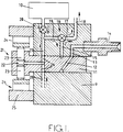
- Figure 1 is a sectional side elevation of one example of part of a fuel system in accordance with the invention,
- Figure 2 is shows various fuel injection rate diagrams which can be obtained from the systems described herein,
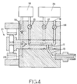
- Figures 3 and 4 show alternative forms of fuel system, and
- Figures 5 and 6 show modifications to the system shown in Figure 1 with Figure 6 showing a series A-E of valve positions.
- Referring to Figure 1 of the drawings there is shown at 10 an accumulator in which liquid fuel is stored at a pressure which is sufficiently high to open the fuel pressure actuated valve members of the fuel injection nozzles of the associated engine.
- In order to charge the accumulator and also to distribute fuel from the accumulator to the injection nozzles in turn there is provided a pump/distributor unit which comprises a
body 9 in which is journaled a rotarycylindrical distributor member 11. The distributor member is driven in timed relationship with the associated engine by means of a drive shaft not shown. Formed in the distributor member is adelivery passage 12 and this can register in turn with a plurality ofoutlet ports 13 which are formed in the body and which are connected tooutlets 14 respectively the outlets in use being connected to the injection nozzles respectively of the associated engine. Each outlet may be provided with the usual form of delivery valve. Thepassage 12 communicates with a circumferential groove formed in the periphery of the distributor member and this groove is in constant communication with acommon port 15 of a twoway valve 16. The valve has afurther port 17 which is connected to adrain passage 18 and a stillfurther port 19 which is connected through an ON/OFF valve 20 to theaccumulator 10. Thevalves - In order to charge the accumulator a high pressure pump generally indicated at 21 is provided and this comprises a
transverse bore 22 formed in a portion of the distributor member which extends from thebody 9. Slidably mounted in the bore is a pair ofpumping plungers 23 which at their outer ends, engagecam followers 24 respectively each cam follower including a roller which engages the internal peripheral surface of anannular cam ring 25. The cam ring is provided in the case of an engine having four cylinders, with four equi-angularly spaced cam lobes which impart inward movement to the plungers as the distributor member is rotated. An additional pair of plungers may be provided and these would be located in a further bore which for the application described would intersect thebore 22 at right angles. For a six cylinder engine the further bore would be located in a plane spaced from the plane containing thebore 22 by 60° and the cam ring would have six cam lobes. - For a five cylinder engine the cam ring would be provided with five cam lobes and five plungers may be provided in individual bores or three plungers may be provided again in individual bores with appropriate spacing of the bores and with one plunger being larger than the other two in order to achieve balance of the forces acting on the distributor member.
- Returning to the example, the portion of the
bore 22 which lies intermediate the plungers is connected to four equi-angularly spacedpassages 26 which open onto the periphery of the distributor member so as to register in turn with atransfer port 27. The transfer port is connected to a point intermediate thevalves passages 26 can register in turn with afuel supply port 28 this port being connected to the outlet of a low pressure pump. This pump may have a rotary part carried by thedistributor member 11 or the rotary part of the pump may be driven directly by the drive shaft. - Ignoring for the moment the action of the
high pressure pump 21 and assuming that theaccumulator 10 is charged with fuel. As the distributor member rotates thedelivery passage 12 will move into register with anoutlet port 13. Before this communication is established thevalve 16 is placed in a first position in which theports port 17 therefore being effectively closed. When delivery of fuel is required thevalve 20 is opened and fuel from the accumulator then flows through thevalves outlet 14. When sufficient fuel has been supplied to the engine thevalve 16 is switched to its second position in which theport 19 is closed, and theport 15 is connected to theport 17. This connection causes a reduction of the fuel pressure within theport 15 and the delivery passages and theoutlet port 13 so that the valve in the associated fuel injection nozzle can close quickly. As the distributor member further rotates thepassage 12 moves out of register with theoutlet port 13 and prior to the next delivery of fuel the valves are switched so that thevalve 20 is closed and thevalve 16 is in its first position in which theports valve 20 controls the supply of fuel from the accumulator and determines the start of delivery of fuel to the engine and thevalve 16 serves to terminate the supply of fuel to the engine. - Considering now the operation of the
high pressure pump 21. The main purpose of this pump is to charge the accumulator with fuel but in the particular example it may also be used to supply an initial quantity of fuel to the engine at a reduced rate. In order to achieve this, as thedelivery passage 12 moves into register with anoutlet port 13, one of thepassages 26 moves into register with thetransfer port 27 and with thevalve 20 closed and thevalve 16 in its first state, as the distributor member rotates, the rollers and therefore theplungers 23, will be moved inwardly as the rollers move off the base circle onto the leading flanks of the cam lobes and fuel will be supplied to the engine. When the required volume of fuel has been supplied at the reduced rate, thevalve 20 is opened and the remaining flow of fuel to the engine takes place at a high rate from theaccumulator 10 as described above. The further fuel displaced by the high pressure pump flows to the accumulator. When the required total quantity of fuel has been supplied to the engine thevalve 16 is actuated to close theport 19 as described above and with thevalve 20 open the remaining quantity of fuel which is displaced by the plungers during their inward movement, flows into theaccumulator 10. As the plungers move over the crests of the cam lobes thepassage 26 moves out of register with thetransfer port 27 and a further one of the passages moves into register with thefuel supply port 28 so that the plungers are now urged outwardly their maximum extent by a fresh supply of fuel obtained from the low pressure pump. The cycle is then repeated and the fuel injection rate diagram which is obtained with this arrangement is shown in Figure 2a. The initial rate at which fuel is delivered to the engine is determined by the cam profile and the timing of the start of fuel delivery can be varied by altering the angular setting of the cam ring. The fuel which flows to theaccumulator 10 from thehigh pressure pump 21 may flow through thevalve 20 as shown in Figure 1. However the accumulator may be divided into two sections which are interconnected through an orifice. Thevalve 20 in this case is modified so that fuel is supplied from one section of the accumulator to the engine and is supplied to the other section of the accumulator by thehigh pressure pump 21. Figure 5 shows one way in which this can be achieved. The two sections of the accumulator are shown at 10A and 10B and are interconnected by a restrictedorifice 9. Thevalve 20 is shown as twoseparate valves valve 20A being a two way valve andvalve 20B an ON/OFF valve. Thevalve 20A has one port connected to thepassage 27 and in one position this port is connected through the valve with the accumulator section 10A. In the alternative position the port is connected directly to theport 19 of thevalve 16. Thevalve 20B is connected between the accumulator section 10B and theport 19 of thevalve 16. The initial delivery of fuel to the engine takes place from the high pressure pump, by way of thevalve 20A and thevalve 16, when sufficient fuel has been delivered to the engine at the reduced rate thevalves - It is necessary to control the pressure in the accumulator and this can be achieved by allowing some of the fuel under pressure in the accumulator to return to the
bore 22 whilst the plungers are under the control of the trailing flanks of the cam lobes. This of course requires thevalve 20 to remain open and for thepassage 26 to remain in communication with theport 27. Theport 28 is phased accordingly. A sensor is provided which provides a signal indicative of the pressure in the accumulator and this signal is supplied to a control system for thevalve 20 which is closed when the accumulator pressure has fallen to the desired value. The pressure in thepassage 27 will then fall to the output pressure of the low pressure pump as fuel is supplied to the bore by way of theport 28. - As an alternative the
ports passage 26. In this case a non-return valve is provided in the connection between theport 28 and the outlet of the low pressure pump. - An alternative way of controlling the pressure in the accumulator is to allow the plungers to charge the accumulator after they have supplied fuel at the initial rate, and when the accumulator pressure has reached the desired value, to direct the remaining quantity of fuel delivered by the plungers to the outlet of the low pressure pump. For this purpose the
valve 20 is replaced by a valve arrangement which can provide a number of alternative flow sequences as follows:- - 1. A first sequence in which the
passages 26 are connected to theport 19 of thevalve 16 to provide the flow of fuel to the engine at the rate determined by thehigh pressure pump 21. - 2. A second sequence in which the
accumulator 10 is connected to theport 19 of thevalve 16 to effect flow of fuel at the high rate to the engine and simultaneously the fuel displaced by the plungers may be supplied to the accumulator. - 3. A third sequence in which the fuel displaced by the high pressure pump is diverted to the low pressure pump because the accumulator pressure has attained the desired value.
- 4. A fourth sequence in which the connection between the
port 15 and theport 19 is broken andport 15 is connected to port 18 as when the desired quantity of fuel has been supplied to the engine and thepassages 26 remain connected to the low pressure pump. This allows any further fuel displaced by the plungers to flow to the low pressure pump and also allows thebore 22 to be refilled. In this case theseparate supply port 28 may not be provided and assistance in filling thebore 22 obtained by providing thevalve 16 with a further position in which theports port 19 being connected to thepassages 26. - Figure 6 shows the modifications required to obtain the aforesaid sequences. The
valve 20 is modified so that it becomes a threeway selector valve 40 having an angularlymovable valve member 41 which defines a flat 42 which is permanently connected to thetransfer port 27. - In addition the valve has three
ports first port 43 is connected to theaccumulator 10, thesecond port 44 is connected to theport 19 of thevalve 16 and thethird port 45 is connected to thepassage 18 which in this case is connected to the outlet of the low pressure pump. - In the position shown in Figure 6 the
valve 40 connects thetransfer port 27 to theport 19 of thevalve 16 and this is set to connect theports delivery passage 12 and anoutlet 13. The delivery of fuel from the accumulator to the outlet is arranged by moving thevalve member 41 angularly so that the flat 42 connects theports accumulator 10. If thevalve member 41 is moved so that the flat 42 connects theports - This system of valves is also applicable in the situation where delivery of fuel to the engine is terminated before the accumulator pressure has achieved the desired value.
- The pressure in the accumulator may be controlled by a relief valve (not shown) which is controlled by the control system in response to a pressure signal.
- As described a single
high pressure pump 21 has been utilised to supply fuel at the low initial rate to the engine and to charge theaccumulator 10 with fuel. As an alternative to the high pressure pump described, the distributor member may be axially movable by means of a face cam to pressurise fuel in a chamber defined by the body and the distributor member. - The two roles of charging the accumulator and supplying fuel at a low initial rate can be undertaken by separate high pressure pumps. Each of these pumps may take the form of the high pressure pump shown in Figure 1 or one of the pumps could be of this type with the other pump being formed by arranging for the distributor member to be axially movable within the
body 9 as mentioned above.
For some engine operating conditions it may be required to supply the initial quantity of fuel at a restricted rate using the high pressure pump as described and then to supply the fuel at only a moderately increased rate from the accumulator source. This can be achieved by reducing the pressure of fuel in theaccumulator 10. The fuel injection rate diagram appropriate to this arrangement is seen in Figure 2c. The fuel pressure in the accumulator can then be increased. Alternatively a second accumulator may be provided in which fuel is stored at the lower pressure and which can be connected to theport 19 and thevalve 16 through a valve similar to thevalve 20. - Under some conditions of engine operation it may not be necessary to provide for the initial quantity of fuel to be supplied at a restricted rate to the engine and in this case the
valve 20 is opened to initiate delivery of fuel to the associated engine at or before the moment when the plungers commence their inward movement. The fuel injection rate diagram which is obtained with this arrangement is shown at Figure 2e. - In other engine operating conditions such as idling, it is convenient to derive all the fuel which is supplied to the engine directly from the
high pressure pump 21 and thevalve 20 is therefore not opened until thevalve 16 is switched to its second position to connect theport 15 with theport 17 to terminate delivery of fuel. Theaccumulator 10 then acts to absorb the remaining fuel displaced by the plungers. The fuel injection rate diagram which is obtained with this arrangement is shown at Figure 2f. - As an alternative the
accumulator 10 may be isolated and after thevalve 16 is operated to terminate delivery of fuel to the engine, the remaining quantity of fuel displaced by the plungers may flow to the drain. - It will be understood that the change in the injection rates takes place in a gradual manner by appropriate operation of the valves or by varying the pressure in the accumulator or by a combination thereof.
- For some engine applications so called pilot injection is required i.e. following the delivery of an initial quantity of fuel to the engine there is a gap before the main quantity of fuel is delivered to the engine. This can be achieved by using the
valves high pressure pump 21 and to direct the fuel to the accumulator.Valve 16 is then operated when fuel is to be supplied at the high rate from the accumulator. The fuel injection rate diagram which is obtained with this arrangement is shown at Figure 2d. - In the arrangement shown in Figure 3, like reference numerals to those used in Figure 1 are utilised for corresponding parts and in this arrangement the
port 19 of thevalve 16 is connected to theaccumulator 10 by way of a restrictor 30 and in parallel with the restrictor is an ON/OFF valve 31. - The
high pressure pump 21 is utilised only to charge theaccumulator 10 and for this purpose thetransfer port 27 is connected to the accumulator by way of anon-return valve 32. The pressure within the accumulator may be controlled using a relief valve or alternatively an arrangement may be provided to control the volume of fuel delivered by the high pressure pump. One way of reducing the fuel flow from the high pressure pump is to use a throttle to restrict the rate at which fuel flows into the pump. As an alternative some form of plunger stroke control may be provided. - In operation, prior to the start of fuel delivery the
valve 31 is closed and thevalve 16 is in the second position in which theports outlet port 13 thevalve 16 is moved to its first position in which theports accumulator 10 to thedelivery passage 12. The rate of flow of fuel is controlled by the size of therestrictor 30. When it is deemed that sufficient fuel has been supplied at the restricted rate, thevalve 31 is opened to allow fuel flow at a substantially unrestricted rate and when sufficient fuel has been supplied to the engine thevalve 16 is moved to its second position so that the flow of fuel from the accumulator is halted and thedelivery passage 12 is vented to the drain. Before the next delivery of fuel takes place thevalve 31 is closed and the process is repeated with fuel being supplied to theoutlets 14 in turn. Thehigh pressure pump 21 is conveniently arranged to charge the accumulator with fuel each time delivery of fuel takes place to the associated engine and the delivery of fuel by the high pressure pump to the accumulator may commence whilst fuel is being supplied to the engine. The fuel injection rate diagram which is obtained with this arrangement is shown at Figure 2b. - As an alternative to the restrictor 30 and the ON/
OFF valve 31, a variable lift valve not shown, may be connected intermediate theaccumulator 10 and theport 19. In this case the variable lift valve may be utilised to initiate delivery of fuel whilst thevalve 16 is in its first position, with thevalve 16 being used to terminate delivery of fuel by moving it to its second position. - In the arrangement which is shown in Figure 4, the
high pressure pump 21 is utilised to charge theaccumulator 10 by way of anon-return valve 32. As in the example of Figure 3 a first ON/OFF valve 35 is provided to connect theaccumulator 10 to thedelivery passage 12 and when this valve is opened fuel flows to the engine at the maximum rate. In order to provide a reduced rate of flow of fuel to the engine asecond accumulator 36 is provided in which fuel is stored at a lower pressure and this accumulator can be connected to thepassage 12 by way of a second ON/OFF valve 37. A third ON/OFF valve 38 is provided to connect thedelivery passage 12 to a drain. In operation, when thedelivery passage 12 registers with anoutlet port 13, thevalve 38 is closed and thevalve 37 opened to allow fuel to flow at a reduced rate to the associated engine because of the lower pressure in theaccumulator 36. When sufficient fuel has been supplied at the reduced rate thevalve 35 is opened and thevalve 37 closed so that the rate of flow of fuel to the engine increases due to the higher pressure in theaccumulator 10. Termination of delivery of fuel to the engine is achieved by closing thevalve 35 and opening thevalve 38. The fuel injection rate diagram which is obtained with this arrangement is shown at Figure 2b. - In some instances all the fuel which is supplied to the engine is derived from the
accumulator 36 to give the fuel injection rate diagram shown at Figure 2g. In other instances at the instant of closure of thevalve 37 thevalve 38 is opened to terminate delivery of fuel to provide so called pilot injection of fuel and at the appropriate time thevalve 38 is closed and thevalve 35 opened to provide the main delivery of fuel. This arrangement gives the fuel injection rate diagram as seen in Figure 2h. - In order to pressurise the accumulator 36 a separate high pressure pump may be provided. Alternatively the
accumulator 36 may be charged from theaccumulator 10 by appropriate operation of thevalves outlet port 14. Individual relief valves may be utilised to control the pressures in theaccumulators accumulator 10 may be controlled by appropriate operation of thevalves
Claims (4)
- A fuel system for supplying fuel to the injection nozzles in turn of a multi-cylinder compression ignition engine comprising an accumulator (10) in which fuel is stored under pressure, means including a delivery passage (12) for distributing fuel to the injection nozzles in turn, valve means (18, 20, 42) operable to connect said accumulator (10) with said delivery passage (12) when it is required to supply fuel to the engine and pump means (21) for charging the accumulator, characterized in that said pump means (21) comprises a high pressure pump having a pumping plunger (23) actuated by a cam (25) in timed relationship with the engine, the valve means having a first setting in which the fuel delivered by the pump (21) is directed to the delivery passage (12) so as to deliver fuel to the engine at a reduced rate, and the valve means having a second setting in which the accumulator (10) is connected to the delivery passage to provide an increased rate of fuel delivery to the engine.
- A fuel system according to Claim 1, characterized in that said valve means (18, 20, 42) has a third setting in which the communication of the pump (21) and the accumulator (10) with the delivery passage (12) is broken and the delivery passage is connected to a drain.
- A fuel system according to Claim 2, characterized in that said valve means comprises an ON/OFF valve (20) connected between the high pressure pump (21) and the accumulator (10) and a two way valve (16) having a first port (15) connected to the delivery passage (12), a second port (19) connected to a point intermediate the high pressure pump and the ON/OFF valve (20) and a third port which is connected to drain.
- A fuel system according to Claim 2, characterized in that said accumulator is divided into first and second sections (10A, 10B) and said valve means comprises a first two way valve (20A) having a first port connected to the high pressure pump (21), a second port which is connected to the first section (10A) of the accumulator and a third port, a second two way valve (16) having a first port (15) connected to the delivery passage (12), a second port (17) connected to drain and a third port (19), the third port of the first and second two way valves (20A, 20B) being connected together and an ON/OFF valve (20B) connected between the second section (10B) of the accumulator and said third ports.
Applications Claiming Priority (4)
| Application Number | Priority Date | Filing Date | Title |
|---|---|---|---|
| GB939318963A GB9318963D0 (en) | 1993-09-14 | 1993-09-14 | Fuel system |
| GB9318969 | 1993-09-14 | ||
| GB939318969A GB9318969D0 (en) | 1993-09-14 | 1993-09-14 | Fuel supply apparatus |
| GB9318963 | 1993-09-14 |
Publications (2)
| Publication Number | Publication Date |
|---|---|
| EP0643220A1 true EP0643220A1 (en) | 1995-03-15 |
| EP0643220B1 EP0643220B1 (en) | 1998-04-22 |
Family
ID=26303511
Family Applications (3)
| Application Number | Title | Priority Date | Filing Date |
|---|---|---|---|
| EP97200928A Expired - Lifetime EP0785356B1 (en) | 1993-09-14 | 1994-09-05 | Fuel supply system |
| EP94306529A Expired - Lifetime EP0643220B1 (en) | 1993-09-14 | 1994-09-05 | Fuel System |
| EP94306533A Expired - Lifetime EP0643221B1 (en) | 1993-09-14 | 1994-09-05 | Fuel Supply Apparatus |
Family Applications Before (1)
| Application Number | Title | Priority Date | Filing Date |
|---|---|---|---|
| EP97200928A Expired - Lifetime EP0785356B1 (en) | 1993-09-14 | 1994-09-05 | Fuel supply system |
Family Applications After (1)
| Application Number | Title | Priority Date | Filing Date |
|---|---|---|---|
| EP94306533A Expired - Lifetime EP0643221B1 (en) | 1993-09-14 | 1994-09-05 | Fuel Supply Apparatus |
Country Status (5)
| Country | Link |
|---|---|
| US (2) | US5746180A (en) |
| EP (3) | EP0785356B1 (en) |
| JP (2) | JPH07180635A (en) |
| DE (3) | DE69409741T2 (en) |
| ES (3) | ES2115882T3 (en) |
Cited By (3)
| Publication number | Priority date | Publication date | Assignee | Title |
|---|---|---|---|---|
| WO2000031409A1 (en) * | 1998-11-25 | 2000-06-02 | Siemens Aktiengesellschaft | Device for producing a variable volumetric flow in a fuel supply |
| DE19952000A1 (en) * | 1999-10-28 | 2001-05-10 | Siemens Ag | Device for generating a variable volume flow for a pump |
| WO2001034965A1 (en) * | 1999-11-11 | 2001-05-17 | Robert Bosch Gmbh | Fuel injection system |
Families Citing this family (48)
| Publication number | Priority date | Publication date | Assignee | Title |
|---|---|---|---|---|
| GB9411345D0 (en) * | 1994-06-07 | 1994-07-27 | Lucas Ind Plc | Fuel supply system |
| GB9422864D0 (en) * | 1994-11-12 | 1995-01-04 | Lucas Ind Plc | Fuel system |
| GB2299138A (en) * | 1995-03-24 | 1996-09-25 | Lucas Ind Plc | Fuel system |
| US5732679A (en) * | 1995-04-27 | 1998-03-31 | Isuzu Motors Limited | Accumulator-type fuel injection system |
| GB9509733D0 (en) * | 1995-05-13 | 1995-07-05 | Lucas Ind Plc | Fuel pumping apparatus |
| GB2310889A (en) * | 1996-03-05 | 1997-09-10 | Lucas Ind Plc | Fuel supply system for solenoid-actuated fuel injectors |
| GB9606493D0 (en) * | 1996-03-23 | 1996-06-05 | Lucas Ind Plc | Fuel pump |
| DE19716221B4 (en) * | 1997-04-18 | 2007-06-21 | Robert Bosch Gmbh | Fuel injection device with pre-injection and main injection in internal combustion engines, in particular for hard to ignite fuels |
| DE59810332D1 (en) * | 1998-01-13 | 2004-01-15 | Siemens Ag | Procedure for specifying the injection pressure setpoint in accumulator injection systems |
| DE19904075A1 (en) * | 1999-02-02 | 2000-08-03 | Bosch Gmbh Robert | Liquid medium delivery arrangement has valve unit between pressure reservoir and distributor arrangement to determine start of delivery and dosing of liquid medium |
| DE19904074A1 (en) * | 1999-02-02 | 2000-08-03 | Bosch Gmbh Robert | Delivery arrangement for liquid medium has step change transmission between electric motor of electric drive arrangement and distributor arrangement |
| DE19904041A1 (en) * | 1999-02-02 | 2000-08-17 | Bosch Gmbh Robert | Input device for fluid medium, valve device of which has several valve units |
| WO2002050421A1 (en) * | 2000-12-06 | 2002-06-27 | Yanmar Co., Ltd. | Three-way valve of accumulator distributing type fuel injection pump |
| ATE421040T1 (en) * | 2002-07-01 | 2009-01-15 | Mitsubishi Heavy Ind Ltd | FUEL INJECTION VALVE AND DIESEL ENGINE WITH IT |
| AU2003210737A1 (en) * | 2003-01-30 | 2004-08-30 | Robert Bosch Gmbh | Fuel injector pump with trapped volume |
| US7398763B2 (en) * | 2005-11-09 | 2008-07-15 | Caterpillar Inc. | Multi-source fuel system for variable pressure injection |
| US7353800B2 (en) | 2006-05-24 | 2008-04-08 | Caterpillar Inc. | Multi-source fuel system having grouped injector pressure control |
| US7431017B2 (en) | 2006-05-24 | 2008-10-07 | Caterpillar Inc. | Multi-source fuel system having closed loop pressure control |
| US7392791B2 (en) | 2006-05-31 | 2008-07-01 | Caterpillar Inc. | Multi-source fuel system for variable pressure injection |
| US8097712B2 (en) | 2007-11-07 | 2012-01-17 | Beelogics Inc. | Compositions for conferring tolerance to viral disease in social insects, and the use thereof |
| US8962584B2 (en) | 2009-10-14 | 2015-02-24 | Yissum Research Development Company Of The Hebrew University Of Jerusalem, Ltd. | Compositions for controlling Varroa mites in bees |
| MX2012010479A (en) | 2010-03-08 | 2012-10-09 | Monsanto Technology Llc | Polynucleotide molecules for gene regulation in plants. |
| US10829828B2 (en) | 2011-09-13 | 2020-11-10 | Monsanto Technology Llc | Methods and compositions for weed control |
| WO2013040057A1 (en) | 2011-09-13 | 2013-03-21 | Monsanto Technology Llc | Methods and compositions for weed control |
| US9416363B2 (en) | 2011-09-13 | 2016-08-16 | Monsanto Technology Llc | Methods and compositions for weed control |
| US10806146B2 (en) | 2011-09-13 | 2020-10-20 | Monsanto Technology Llc | Methods and compositions for weed control |
| PL2755467T3 (en) | 2011-09-13 | 2018-01-31 | Monsanto Technology Llc | Methods and compositions for weed control |
| UA116090C2 (en) | 2011-09-13 | 2018-02-12 | Монсанто Текнолоджи Ллс | Methods and compositions for weed control |
| US10760086B2 (en) | 2011-09-13 | 2020-09-01 | Monsanto Technology Llc | Methods and compositions for weed control |
| US10240161B2 (en) | 2012-05-24 | 2019-03-26 | A.B. Seeds Ltd. | Compositions and methods for silencing gene expression |
| US10683505B2 (en) | 2013-01-01 | 2020-06-16 | Monsanto Technology Llc | Methods of introducing dsRNA to plant seeds for modulating gene expression |
| AU2013371825B2 (en) | 2013-01-01 | 2019-10-24 | A.B. Seeds Ltd. | Methods of introducing dsRNA to plant seeds for modulating gene expression |
| US20140261321A1 (en) * | 2013-03-13 | 2014-09-18 | Electro-Motive Diesel, Inc. | Fuel system having rotary distributor |
| UA123082C2 (en) | 2013-03-13 | 2021-02-17 | Монсанто Текнолоджи Ллс | Methods and compositions for weed control |
| AR095233A1 (en) | 2013-03-13 | 2015-09-30 | Monsanto Technology Llc | METHODS AND COMPOSITIONS FOR WEED CONTROL |
| US10568328B2 (en) | 2013-03-15 | 2020-02-25 | Monsanto Technology Llc | Methods and compositions for weed control |
| CA2918387C (en) | 2013-07-19 | 2021-11-02 | Monsanto Technology Llc | Compositions and methods for controlling leptinotarsa |
| US9850496B2 (en) | 2013-07-19 | 2017-12-26 | Monsanto Technology Llc | Compositions and methods for controlling Leptinotarsa |
| NZ719544A (en) | 2013-11-04 | 2022-09-30 | Beeologics Inc | Compositions and methods for controlling arthropod parasite and pest infestations |
| UA119253C2 (en) | 2013-12-10 | 2019-05-27 | Біолоджикс, Інк. | Compositions and methods for virus control in varroa mite and bees |
| WO2015108982A2 (en) | 2014-01-15 | 2015-07-23 | Monsanto Technology Llc | Methods and compositions for weed control using epsps polynucleotides |
| EP3420809A1 (en) | 2014-04-01 | 2019-01-02 | Monsanto Technology LLC | Compositions and methods for controlling insect pests |
| CN106795515B (en) | 2014-06-23 | 2021-06-08 | 孟山都技术公司 | Compositions and methods for modulating gene expression via RNA interference |
| EP3161138A4 (en) | 2014-06-25 | 2017-12-06 | Monsanto Technology LLC | Methods and compositions for delivering nucleic acids to plant cells and regulating gene expression |
| WO2016018887A1 (en) | 2014-07-29 | 2016-02-04 | Monsanto Technology Llc | Compositions and methods for controlling insect pests |
| US10968449B2 (en) | 2015-01-22 | 2021-04-06 | Monsanto Technology Llc | Compositions and methods for controlling Leptinotarsa |
| UY36703A (en) | 2015-06-02 | 2016-12-30 | Monsanto Technology Llc | COMPOSITIONS AND METHODS FOR THE ADMINISTRATION OF A POLINUCLEOTIDE ON A PLANT |
| AU2016270913A1 (en) | 2015-06-03 | 2018-01-04 | Monsanto Technology Llc | Methods and compositions for introducing nucleic acids into plants |
Citations (2)
| Publication number | Priority date | Publication date | Assignee | Title |
|---|---|---|---|---|
| FR2093250A5 (en) * | 1970-06-08 | 1972-01-28 | Peugeot | |
| EP0406592A2 (en) * | 1989-07-06 | 1991-01-09 | Robert Bosch Gmbh | Fuel injection pump |
Family Cites Families (16)
| Publication number | Priority date | Publication date | Assignee | Title |
|---|---|---|---|---|
| US4083345A (en) * | 1975-10-14 | 1978-04-11 | Stanadyne, Inc. | Fuel injection pump |
| ES481775A1 (en) * | 1978-08-03 | 1980-02-16 | Lucas Industries Ltd | Liquid fuel pumping apparatus |
| DE3011831A1 (en) * | 1980-03-27 | 1981-10-01 | Robert Bosch Gmbh, 7000 Stuttgart | FUEL INJECTION PUMP FOR INTERNAL COMBUSTION ENGINES |
| GB2079366B (en) * | 1980-07-03 | 1984-03-28 | Lucas Industries Ltd | Fuel system for compression ignition engines |
| DE3123138A1 (en) * | 1981-06-11 | 1982-12-30 | Robert Bosch Gmbh, 7000 Stuttgart | FUEL INJECTION PUMP |
| DE3248713A1 (en) * | 1982-12-31 | 1984-07-05 | Robert Bosch Gmbh, 7000 Stuttgart | METHOD FOR INJECTION OF FUEL AND FUEL INJECTION DEVICE FOR CARRYING OUT THE METHOD |
| GB8417862D0 (en) * | 1984-07-13 | 1984-08-15 | Lucas Ind Plc | Fuel pumping apparatus |
| GB8417861D0 (en) * | 1984-07-13 | 1984-08-15 | Lucas Ind Plc | Fuel pumping apparatus |
| FR2586456B1 (en) * | 1985-08-21 | 1989-07-07 | Lucas France | FUEL INJECTION PUMP WITH ROTARY DISTRIBUTOR FOR SUPPLYING INTERNAL COMBUSTION ENGINES |
| US4757795A (en) * | 1986-04-21 | 1988-07-19 | Stanadyne, Inc. | Method and apparatus for regulating fuel injection timing and quantity |
| DE3844363A1 (en) * | 1988-12-30 | 1990-07-05 | Bosch Gmbh Robert | Electrically controlled fuel injection pump |
| DE3903313A1 (en) * | 1989-02-04 | 1990-08-09 | Bosch Gmbh Robert | STORAGE FUEL INJECTION DEVICE |
| DE4023307A1 (en) * | 1990-07-21 | 1992-01-23 | Bosch Gmbh Robert | FUEL INJECTION DEVICE FOR FOREIGN IGNITION COMBUSTION ENGINES |
| US5215060A (en) * | 1991-07-16 | 1993-06-01 | Stanadyne Automotive Corp. | Fuel system for rotary distributor fuel injection pump |
| DE4304967A1 (en) * | 1992-04-25 | 1993-10-28 | Bosch Gmbh Robert | Fuel injection unit for IC engine with high pressure pump - drawing fuel via filling valve to pump working chamber defined by pump piston and delivers by valve at high pressure to HP storage |
| DE59301885D1 (en) * | 1992-04-25 | 1996-04-18 | Bosch Gmbh Robert | FUEL INJECTION DEVICE FOR INTERNAL COMBUSTION ENGINES |
-
1994
- 1994-09-05 ES ES94306529T patent/ES2115882T3/en not_active Expired - Lifetime
- 1994-09-05 DE DE69409741T patent/DE69409741T2/en not_active Expired - Lifetime
- 1994-09-05 DE DE69409743T patent/DE69409743T2/en not_active Expired - Lifetime
- 1994-09-05 EP EP97200928A patent/EP0785356B1/en not_active Expired - Lifetime
- 1994-09-05 DE DE69424448T patent/DE69424448T2/en not_active Expired - Lifetime
- 1994-09-05 ES ES97200928T patent/ES2146952T3/en not_active Expired - Lifetime
- 1994-09-05 EP EP94306529A patent/EP0643220B1/en not_active Expired - Lifetime
- 1994-09-05 EP EP94306533A patent/EP0643221B1/en not_active Expired - Lifetime
- 1994-09-05 ES ES94306533T patent/ES2115883T3/en not_active Expired - Lifetime
- 1994-09-09 US US08/303,695 patent/US5746180A/en not_active Expired - Lifetime
- 1994-09-09 US US08/303,696 patent/US5427066A/en not_active Expired - Lifetime
- 1994-09-12 JP JP6242359A patent/JPH07180635A/en active Pending
- 1994-09-14 JP JP6244893A patent/JPH07167001A/en active Pending
Patent Citations (2)
| Publication number | Priority date | Publication date | Assignee | Title |
|---|---|---|---|---|
| FR2093250A5 (en) * | 1970-06-08 | 1972-01-28 | Peugeot | |
| EP0406592A2 (en) * | 1989-07-06 | 1991-01-09 | Robert Bosch Gmbh | Fuel injection pump |
Cited By (8)
| Publication number | Priority date | Publication date | Assignee | Title |
|---|---|---|---|---|
| WO2000031409A1 (en) * | 1998-11-25 | 2000-06-02 | Siemens Aktiengesellschaft | Device for producing a variable volumetric flow in a fuel supply |
| DE19854509A1 (en) * | 1998-11-25 | 2000-06-08 | Siemens Ag | Device for generating a variable volume flow when supplying fuel |
| DE19854509C2 (en) * | 1998-11-25 | 2000-11-23 | Siemens Ag | Device for generating a variable volume flow when supplying fuel |
| US6293250B1 (en) | 1998-11-25 | 2001-09-25 | Siemens Aktiengesellschaft | Apparatus for producing a variable volumetric flow in a fuel feed system |
| USRE38192E1 (en) | 1998-11-25 | 2003-07-22 | Siemens Aktiengesellschaft | Apparatus for producing a variable volumetric flow in a fuel feed system |
| DE19952000A1 (en) * | 1999-10-28 | 2001-05-10 | Siemens Ag | Device for generating a variable volume flow for a pump |
| DE19952000C2 (en) * | 1999-10-28 | 2001-08-16 | Siemens Ag | Device for generating a variable volume flow for a pump |
| WO2001034965A1 (en) * | 1999-11-11 | 2001-05-17 | Robert Bosch Gmbh | Fuel injection system |
Also Published As
| Publication number | Publication date |
|---|---|
| DE69409743T2 (en) | 1998-10-22 |
| EP0643221A1 (en) | 1995-03-15 |
| ES2115883T3 (en) | 1998-07-01 |
| US5746180A (en) | 1998-05-05 |
| DE69409741T2 (en) | 1999-04-08 |
| DE69424448D1 (en) | 2000-06-15 |
| JPH07180635A (en) | 1995-07-18 |
| JPH07167001A (en) | 1995-07-04 |
| EP0643221B1 (en) | 1998-04-22 |
| EP0785356A2 (en) | 1997-07-23 |
| DE69424448T2 (en) | 2000-12-21 |
| EP0785356A3 (en) | 1997-10-29 |
| EP0643220B1 (en) | 1998-04-22 |
| DE69409743D1 (en) | 1998-05-28 |
| US5427066A (en) | 1995-06-27 |
| DE69409741D1 (en) | 1998-05-28 |
| ES2146952T3 (en) | 2000-08-16 |
| ES2115882T3 (en) | 1998-07-01 |
| EP0785356B1 (en) | 2000-05-10 |
Similar Documents
| Publication | Publication Date | Title |
|---|---|---|
| US5427066A (en) | Fuel system | |
| US5642714A (en) | Fuel system | |
| EP0652394B1 (en) | Control valve | |
| US4407250A (en) | Fuel injection system | |
| US4242059A (en) | Fuel pumping apparatus | |
| US4446836A (en) | Fuel injection pumping apparatus | |
| US5613839A (en) | Variable rate pump | |
| US4764092A (en) | Liquid fuel injection pump | |
| US5619970A (en) | Fuel pumping apparatus | |
| US4140095A (en) | Liquid fuel pumping apparatus | |
| GB2196153A (en) | Fuel system for a multi-cylinder engine | |
| US5207202A (en) | Fuel pumping apparatus | |
| US5101798A (en) | Fuel pumping apparatus | |
| US3398730A (en) | Fuel injection system and distributor valve therefor | |
| US20060159572A1 (en) | Pilot injection pump | |
| EP0640760B1 (en) | Fuel pump | |
| US5462033A (en) | Fuel pumping apparatus | |
| US4493621A (en) | Fuel injection pumping apparatus | |
| US5947707A (en) | Fuel pump with a cam having first and second plunger displacement regions | |
| GB1577952A (en) | Fuel injection pumping apparatus | |
| GB2304385A (en) | Distributor pump for fuel | |
| GB2306999A (en) | I.c. engine fuel supply system with an accumulator and pressure control means | |
| JPS5620724A (en) | Fuel injection pump for diesel engine | |
| US4383806A (en) | Fuel pumping apparatus | |
| GB2090341A (en) | Fuel injection pumping apparatus |
Legal Events
| Date | Code | Title | Description |
|---|---|---|---|
| PUAI | Public reference made under article 153(3) epc to a published international application that has entered the european phase |
Free format text: ORIGINAL CODE: 0009012 |
|
| AK | Designated contracting states |
Kind code of ref document: A1 Designated state(s): DE ES FR GB IT |
|
| 17P | Request for examination filed |
Effective date: 19950804 |
|
| 17Q | First examination report despatched |
Effective date: 19961230 |
|
| GRAG | Despatch of communication of intention to grant |
Free format text: ORIGINAL CODE: EPIDOS AGRA |
|
| RAP1 | Party data changed (applicant data changed or rights of an application transferred) |
Owner name: LUCAS INDUSTRIES PUBLIC LIMITED COMPANY |
|
| GRAG | Despatch of communication of intention to grant |
Free format text: ORIGINAL CODE: EPIDOS AGRA |
|
| GRAH | Despatch of communication of intention to grant a patent |
Free format text: ORIGINAL CODE: EPIDOS IGRA |
|
| GRAH | Despatch of communication of intention to grant a patent |
Free format text: ORIGINAL CODE: EPIDOS IGRA |
|
| GRAA | (expected) grant |
Free format text: ORIGINAL CODE: 0009210 |
|
| AK | Designated contracting states |
Kind code of ref document: B1 Designated state(s): DE ES FR GB IT |
|
| ITF | It: translation for a ep patent filed |
Owner name: BUGNION S.P.A. |
|
| REF | Corresponds to: |
Ref document number: 69409741 Country of ref document: DE Date of ref document: 19980528 |
|
| ET | Fr: translation filed | ||
| REG | Reference to a national code |
Ref country code: ES Ref legal event code: FG2A Ref document number: 2115882 Country of ref document: ES Kind code of ref document: T3 |
|
| PLBE | No opposition filed within time limit |
Free format text: ORIGINAL CODE: 0009261 |
|
| STAA | Information on the status of an ep patent application or granted ep patent |
Free format text: STATUS: NO OPPOSITION FILED WITHIN TIME LIMIT |
|
| 26N | No opposition filed | ||
| REG | Reference to a national code |
Ref country code: FR Ref legal event code: CD |
|
| REG | Reference to a national code |
Ref country code: GB Ref legal event code: 732E |
|
| REG | Reference to a national code |
Ref country code: FR Ref legal event code: TP |
|
| REG | Reference to a national code |
Ref country code: GB Ref legal event code: IF02 |
|
| PGFP | Annual fee paid to national office [announced via postgrant information from national office to epo] |
Ref country code: GB Payment date: 20020902 Year of fee payment: 9 |
|
| PGFP | Annual fee paid to national office [announced via postgrant information from national office to epo] |
Ref country code: ES Payment date: 20030822 Year of fee payment: 10 |
|
| PG25 | Lapsed in a contracting state [announced via postgrant information from national office to epo] |
Ref country code: GB Free format text: LAPSE BECAUSE OF NON-PAYMENT OF DUE FEES Effective date: 20030905 |
|
| GBPC | Gb: european patent ceased through non-payment of renewal fee | ||
| PG25 | Lapsed in a contracting state [announced via postgrant information from national office to epo] |
Ref country code: ES Free format text: LAPSE BECAUSE OF NON-PAYMENT OF DUE FEES Effective date: 20040906 |
|
| PG25 | Lapsed in a contracting state [announced via postgrant information from national office to epo] |
Ref country code: IT Free format text: LAPSE BECAUSE OF NON-PAYMENT OF DUE FEES;WARNING: LAPSES OF ITALIAN PATENTS WITH EFFECTIVE DATE BEFORE 2007 MAY HAVE OCCURRED AT ANY TIME BEFORE 2007. THE CORRECT EFFECTIVE DATE MAY BE DIFFERENT FROM THE ONE RECORDED. Effective date: 20050905 |
|
| REG | Reference to a national code |
Ref country code: ES Ref legal event code: FD2A Effective date: 20040906 |
|
| PGFP | Annual fee paid to national office [announced via postgrant information from national office to epo] |
Ref country code: FR Payment date: 20080915 Year of fee payment: 15 |
|
| PGFP | Annual fee paid to national office [announced via postgrant information from national office to epo] |
Ref country code: DE Payment date: 20090903 Year of fee payment: 16 |
|
| REG | Reference to a national code |
Ref country code: FR Ref legal event code: ST Effective date: 20100531 |
|
| PG25 | Lapsed in a contracting state [announced via postgrant information from national office to epo] |
Ref country code: FR Free format text: LAPSE BECAUSE OF NON-PAYMENT OF DUE FEES Effective date: 20090930 |
|
| REG | Reference to a national code |
Ref country code: DE Ref legal event code: R119 Ref document number: 69409741 Country of ref document: DE Effective date: 20110401 |
|
| PG25 | Lapsed in a contracting state [announced via postgrant information from national office to epo] |
Ref country code: DE Free format text: LAPSE BECAUSE OF NON-PAYMENT OF DUE FEES Effective date: 20110401 |