EP0643171B1 - Dispositif de repassage des marquages routiers longitudinaux - Google Patents
Dispositif de repassage des marquages routiers longitudinaux Download PDFInfo
- Publication number
- EP0643171B1 EP0643171B1 EP19940402030 EP94402030A EP0643171B1 EP 0643171 B1 EP0643171 B1 EP 0643171B1 EP 19940402030 EP19940402030 EP 19940402030 EP 94402030 A EP94402030 A EP 94402030A EP 0643171 B1 EP0643171 B1 EP 0643171B1
- Authority
- EP
- European Patent Office
- Prior art keywords
- spray
- gun assembly
- marking
- vehicle
- road
- Prior art date
- Legal status (The legal status is an assumption and is not a legal conclusion. Google has not performed a legal analysis and makes no representation as to the accuracy of the status listed.)
- Expired - Lifetime
Links
Images



Classifications
-
- E—FIXED CONSTRUCTIONS
- E01—CONSTRUCTION OF ROADS, RAILWAYS, OR BRIDGES
- E01C—CONSTRUCTION OF, OR SURFACES FOR, ROADS, SPORTS GROUNDS, OR THE LIKE; MACHINES OR AUXILIARY TOOLS FOR CONSTRUCTION OR REPAIR
- E01C23/00—Auxiliary devices or arrangements for constructing, repairing, reconditioning, or taking-up road or like surfaces
- E01C23/16—Devices for marking-out, applying, or forming traffic or like markings on finished paving; Protecting fresh markings
- E01C23/163—Devices for marking-out, applying, or forming traffic or like markings on finished paving; Protecting fresh markings for marking-out the location of the markings; Guiding or steering devices for marking apparatus, e.g. sights
Definitions
- the present invention relates to an ironing device for longitudinal road markings comprising a vehicle, at least one first set of guns to spray ironing materials on a longitudinal road marking, this set of pistols being secured to the lower part of the vehicle and directed towards the road.
- Such a device also includes control means opening and closing of the gun assembly, as well as a near vision, associated with a local control unit and comprising a local optical sensor, placed near the gun assembly and intended for locally view the marking to be ironed.
- This local optical sensor is associated with signal processing means and calculation means for determine the position of the theoretical longitudinal axis of the marking to iron.
- the device further comprises means for positioning the gun set.
- theoretical longitudinal axis of the marking the axis determined locally precisely, while the axis longitudinal “approximate” is the global axis of the marking, for example such as the sees the driver of the vehicle.
- the guns can be rotate around a vertical axis and around a horizontal axis.
- This known device has several drawbacks. Indeed, from share, and although it is partially automated, the ironing speed it allows is limited since the near vision system must locally identify the contours of each element of road markings, analyze the data and transmit, each time, the command to open and closing of the guns and the control for adjusting their position.
- this device requires a sustained attention from the driver of the vehicle, who must constantly take care to generally keep the vehicle in line with the marking at iron. This also limits the speed of ironing.
- the pistols having a defined opening angle must be placed at a specific height above the road so that the projection width of the materials of ironing corresponds to the width of the markings to be ironed.
- these pistols must be precisely positioned on the axis of the marking and their opening / closing sequence must be such that, depending on the speed of the vehicle, they are open for a time necessary to iron the lines constituting the marking to be ironed, and closed on the intervals between these traits.
- the device known from document EP-A-0129 551 is not suitable for the simultaneous ironing of two longitudinal road markings, respectively placed on the axis and on the bank of the road.
- the invention aims to remedy these drawbacks by proposing a Longitudinal road marking ironing device which allows increased ironing speed and improves ironing accuracy.
- the means for positioning the gun assembly comprise first means of vertical displacement of the first pistol assembly, first means of horizontal displacement of the first set of pistols, intended to move said set horizontally, in a direction transverse to the direction of movement of the vehicle, and of the first means for adjusting the first set of pistols.
- the device further comprises a main means servo system comprising a far vision system associated with a main control unit, said far vision system comprising a global optical sensor to visualize the width, the module and the position of the longitudinal axis of the first iron-on marking, associated with means signal processing and calculation means to determine the width, the module and the position of the approximate longitudinal axis of the first marking to be ironed, said main control unit being intended to control the first means of vertical displacement of the first set to pistols, so as to match the projection width of the ironing materials with the width of the first marking to be ironed, order the first means of horizontal movement of the first pistol assembly, so as to place said assembly above the axis longitudinal approach to the first marking to be ironed, and to order the first means for controlling the opening and closing of the first set of pistols, so as to match the sequences of projection of ironing materials with the module of the first marking at iron.
- a main means servo system comprising a far vision system associated with a main control unit, said far vision system comprising
- the first near vision system and the first unit of local control are part of a first secondary means servo control, said first local control unit being intended for controlling said first adjustment means of the first set to pistols, so as to correct the controls of the control unit main.
- the means for adjusting the first gun assembly may include horizontal adjustment means of the latter, which the local control unit commands to correct the position of this first set of pistols and make it coincide with the axis theoretical longitudinal of the marking to be ironed.
- These adjustment means can also include means vertical adjustment of the first set of guns, controlled by the unit local control to obtain a projection width equal to that of the marking and thus refining the control of the main control unit.
- They may also include means for adjusting the opening and closing of the guns.
- the invention allows tolerances of deviations from the larger vehicle path.
- the speed of ironing can be increased.
- the far vision system associated with the control unit main, used to globally configure the guns. Determining the marking module is particularly important, since it allows calculate the opening and closing sequences of the guns. So, when the vehicle is moving at constant speed over a section on which the marking module remains unchanged, opening and closing of pistols do not require any additional transmission. However, when the far vision system detects a modification of the module, the sequence opening and closing of the guns is modified.
- the main means of control determines, using the system far vision, the ironing marking module. He can then, in depending on the vehicle speed, calculate the opening and closing times gun closure, depending on which he commands directly opening and closing.
- the secondary control means can intervene by means of adjustment, to take into account possible local variations in the marking module or variations momentary vehicle speed.
- the main means of control determines that the duration of the opening of the pistols, the secondary means control then giving the command to open the guns, these being automatically closed, after the time prescribed by the unit main control.
- control unit main preposition the pistols by controlling the means of horizontal and vertical displacement, so that the secondary means has only to readjust their position if the need arises locally feel.
- Gun sets are generally made up of three pistols, the first projecting paint, mixed before being deposited on the road to microbeads of reflective glass projected by the second, and the third projecting a layer of glass microbeads used to improve the thinking and increasing the life of road markings.
- the device according to the invention can be used with a single set with guns for ironing with a single marking or with two sets of pistols, for example, in axis and in edge, for the ironing of two axis and shore markings respectively.
- the far vision system therefore views the road ahead of the vehicle, possibly over a width sufficient to encompass the axis and shore markings.
- the invention comprises one or two secondary means of control according to the number of sets with pistols.
- a secondary means servo associated with a set of pistols In case the device of the invention comprises two sets of pistols, both associated control means operate in such a way independent of each other.
- the operation of the second means secondary control being analogous to that of the first means secondary control, described above.
- a set of pistols or the two gun assemblies can be integral with one or two trolleys, themselves secured to the lower part of the vehicle.
- This or these carriages are connected to the vehicle by a vertical displacement member, allowing, during the transfer of the vehicle to raise the carts and authorize normal speed.
- These carts are fitted with wheels which are placed at the road surface contact, through the body of vertical movement of the carriage, with a view to ironing the markings.
- the device also comprises a member for horizontal displacement of carriage, in a direction transverse to the direction of travel of the vehicle. This horizontal carriage movement member can be part aforementioned means for horizontal movement of the gun assembly.
- the gun assemblies preferably being placed halfway transverse by their horizontal adjustment means, to pre-position said assemblies substantially above the approximate axis of the marking to iron.
- the horizontal adjustment and transverse pistol assemblies will be at most a setting relative, of limited amplitude.
- the means of vertical displacement of pistol assemblies, as well as their possible means of adjustment vertical move said assemblies relative to the carriages, more precisely, relative to a part of the carriages kept at a distance substantially constant from the road surface thanks to the wheels of these carts, to determine the projection width of the materials of ironing.
- the carriages are advantageously provided with a suspension by through which they are connected to the vehicle.
- This suspension allows the vertical movements of the vehicle to be decoupled from those of the carts to keep them connected to the road.
- the sensor (s) local optics are advantageously mounted on these carriages.
- the assemblies to pistols are mounted on supporting structures such as chassis, secured to the vehicle by vertical displacement members and, possibly horizontal displacement members, while the one or more near vision systems are equipped with distance sensors. These latter measure the distance between the supporting structures and the road surface. If this measured distance deviates from the target height at which one wishes maintain the supporting structures, the secondary means or means servo control the vertical displacement members for correct the discrepancy. These provisions make it possible to maintain the pistols at the desired height, even if the road has local reliefs.
- the distance sensors are for example constituted by ultrasonic systems or, more generally, by measurement systems without contact.
- the vertical displacement members of the supporting structures can then play the role of means of vertical displacement of the assemblies to pistols. In this case they are generally controlled by the unit of main control and are, if necessary, readjusted by the control unit corresponding secondary.
- the vertical displacement means and the adjustment means vertical of a set of pistols can consist of the same organ, generally controlled by the main control unit, and regulated precisely by the corresponding local control unit.
- a local optical sensor can visualize approximately 50 cm in width road.
- the near vision system includes means to process the image viewed line by line from an edge of the region viewed.
- each line processed corresponds to 1 cm of road width.
- This near vision system includes also a memory functioning like First In / First Out batteries, which stores at most 15 consecutive values each of which corresponds to a line processed. This makes it possible to determine, to the nearest centimeter, the width of the lines constituting the iron-on marking and the position of the side edges of these traits. The following calculations effectively determine the theoretical axis of the marking by eliminating the sources of error, so as to wedge the guns on this axis.
- the global optical sensor is advantageously secured to the vehicle and placed on its front part, preferably at a height sufficient for its field of vision is adapted to the simultaneous viewing of axis and shore markings.
- the various main and local control units, as well as the calculation means and the signal processing means are advantageously on board the vehicle.
- the main control unit controls the connection and disconnection of the secondary control means (s). More specifically, in case the far vision system spots a marking non-longitudinal, for example a transverse stop marking or a middle marking with zebras, the main control unit disconnects the secondary control means and controls the closing of the gun assembly (s). In case the markings not longitudinal make way for longitudinal markings, the unit of main control reconnects the secondary control means. When two markings are ironed and in the case where only one of them becomes non-longitudinal, disconnection only affects the pistol assembly concerned.
- the main control unit controls the means of command to open and close gun assemblies in operation the ironing markings module and the vehicle speed.
- the optical sensors, global and premises are constituted by cameras and the processing means of the signal are image processing means. It goes without saying that these means signal processing or image processing may consist of a single calculation system, connected to the various optical sensors.
- Figure 1 shows schematically, seen from the front, a vehicle, such as that of Figure 3, provided with the device according to the invention.
- the organization of the various elements is explained by the organization chart of Figure 6.
- the device for ironing longitudinal road markings comprises a vehicle 10 and a first set to pistols 12 intended to spray ironing materials on a first longitudinal road marking A.
- the device also includes first means of vertical displacement of the first set of pistols 12. These means can consist of a displacement member 14 vertical, for example a rack or a hydraulic cylinder, of a motor 15 and a control circuit 16.
- First means of movement horizontal of the first set of pistols 12 are provided and are intended for moving said gun assembly in a direction transverse to the direction of movement of the vehicle 10. These means of movement horizontal may be constituted by a displacement member 18 horizontal, for example a rack or a hydraulic cylinder, a motor 19 and a control circuit 20.
- the device further comprises first means for controlling the opening and closing of the first set of pistols 12. These means are for example constituted by a valve or valve 22, motor 23 and actuator 24.
- This device also comprises a main means servo system comprising a far vision system associated with a UCP main control unit.
- the far vision system includes a global optical sensor 30 to visualize the roadway and the markings, as well as means for processing the TS signal and means MC calculation to determine, depending on the image of the optical sensor overall 30, the width L, the module M and the position of the longitudinal axis approached marking A to be ironed.
- the main UCP control unit is used to control the first means 14,15,16 for vertical displacement of the first assembly at pistols 12, so as to match the projection width of the ironing materials with the width L of the first marking A to be ironed. It is therefore by adjusting the height of the pistols relative to the road that we adapts the projection width to that of the marking, which, the orientation of pistols with respect to the road remaining unchanged, is done in a very precise.
- This main UCP control unit is also used for control the first means 18, 19, 20 for horizontal displacement of the first set of pistols 12, so as to place it above the axis longitudinal approach to the first marking to be ironed.
- the unit of main control UCP is still used to control the means 22, 23, 24 for opening and closing the first set of guns 12, so as to match the projection sequences of ironing materials with module M of the first marking A to iron.
- the device according to the invention comprises a first means secondary control comprising a first vision system close associated with a first local control unit UCL1.
- This first near vision system comprises a first local optical sensor 40, placed near the first set of pistols 12 and intended to display locally the first marking A to be ironed.
- the first optical sensor room 40 is associated with signal processing means TS1 and with MC1 calculation means for determining the position of the longitudinal axis theoretical of the first marking to be ironed.
- the first local control unit UCL1 controls the first horizontal adjustment means of the first gun assembly 12, so as to correct the position of said assembly and to make it coincide with the theoretical longitudinal axis of the first marking A to redo.
- These first horizontal adjustment means include a horizontal displacement member 42, a motor 43 and a circuit command 44.
- the unit local control does not control any additional horizontal adjustment of the gun assembly.
- the device of the invention further comprises a second assembly to pistols 13, integral with the lower part of the vehicle 10, directed towards the road and intended to project ironing materials on a second longitudinal road marking A '.
- These two sets of pistols 12 and 13 are for example respectively placed in axis and along the road.
- the far vision system includes means (global optical sensor 30, means for processing the signal TS and calculation means MC) to determine the widths L and L ', the modules M and M 'and the positions of the approximate longitudinal axes of the two markings A and A 'to be ironed.
- the main control unit UCP is then intended to control simultaneously the first and second vertical displacement means first and second pistol sets 12 and 13, the first and second means of horizontal displacement of the first and second sets with pistols and the first and second opening control means and closing the first and second gun assemblies, this so to match the projection widths of ironing materials from each set of pistols with the widths L and L 'of the two markings iron, to place each of the two sets of guns respectively above the two approximate axes of the two markings to be ironed and made match the projection sequences to modules M and M 'of the two ironing marks.
- a second secondary control means is provided for the second set of pistols 13. It includes a second vision system close and a second local control unit. Like the first, the second near vision system includes a second local optical sensor 40 ', placed near the second set of pistols 13 and intended to locally view the second marking to be ironed. This 40 'sensor is associated with TS2 signal processing means and calculation means MC2 to determine the position of the theoretical longitudinal axis of the second marking A 'to be ironed.
- the second local control unit UCL2 control of the second horizontal adjustment means 42 ', 43', 44 'of the second set of pistols 13, so as to correct and position it coincide with the theoretical longitudinal axis of the second marking to be ironed.
- a set of pistols or the two gun assemblies 12, 13 are integral with a carriage or two carts 50, 50 '.
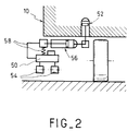
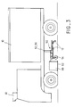
- One of these carriages is shown in detail in Figures 4 and 5, while the transfer and use positions are respectively presented by Figures 2 and 3.
- Figures 4 and 5 the transfer and use positions are respectively presented by Figures 2 and 3.
- the carriage 50 is integral with the lower part of the vehicle 10 by via a member 52 for vertically moving the carriage, intended to raise the carriage 50 when transferring the vehicle 10 and place its wheels 54 in contact with the road surface when ironing a road marking.
- a member 56 of horizontal carriage movement integral with the vehicle or of the member 52, is capable of horizontally moving the carriage 50 transversely to the direction of movement of the vehicle 10, with a view to place in an area of the road that has an iron-on marking.
- This horizontal displacement member 56 may be part of the means of horizontal movement 18, 19, 20 or 18 ', 19', 20 'of the gun assembly 12 or 13 considered.
- a suspension 58 is advantageously provided between the carriage 50 and the lower part of the vehicle 10. This suspension allows, regardless of the vertical movements of the vehicle, maintain the trolley at a constant height above the road surface. She can, moreover, be associated with blocking means, capable of blocking the carriage 50 in the raised position during its transfer.
- the local optical sensor 40 or 40 ' is integral and placed inside a box 60 which has a wall upper and side walls. The free end of these side walls is directed towards the road surface and is at least a very short distance away of this surface.
- Lighting means 64 are placed in the box 60, so as to illuminate the part of the road viewed by the optical sensor local concerned.
- a strip of flexible material 62 is advantageously fixed at the free ends of the side walls of the box 60, so that touch the road surface and prevent all natural light from inside the box.
- each carriage can be replaced by a supporting structure, integral with the vehicle but not coming into contact with the road.
- This structure which carries the set of pistols corresponding, is then connected to the vehicle by displacement members vertical.
- the near vision system associated with the pistol assembly that carries the supporting structure includes a distance sensor which measures the height compared to the road.
- the vertical displacement members of the supporting structure are controlled, preferably by the secondary servo means corresponding, so as to keep the height of the structure constant carrier in relation to the road.
- the structure can also be associated with organs of horizontal displacement, used to place it globally in the axis of the ironing marking.
- the vertical and horizontal displacement members of the supporting structure can respectively be part of the means of vertical and horizontal movement of the corresponding pistol assembly and be controlled by the main control unit according to the width and position of the approximate axis of the marking to be ironed.
- these displacement organs horizontal and vertical can then be controlled by means corresponding secondary control.
- the means of horizontal adjustment mentioned above are part of the displacement members horizontal.
- the gun assembly may be provided with horizontal, but also vertical adjustment means, locally controlled by the corresponding secondary servo means, and displacing the pistol assembly with respect to the supporting structure.
- the local optical sensor 40 or 40 ′ and the box 60 can be mounted on the carriage 50 or 50 ', or on the supporting structure.
- the sensor local optics is preferably at least partially integral in horizontal movement of the corresponding gun assembly, but there does not necessarily accompany horizontal adjustment.
- a local optical sensor 40 or 40 ' preferably displays approximately 50 cm road width.
- the near vision system advantageously includes means signal processing and computing means to process the image displayed line by line, from an edge of the displayed region.
- each line treated corresponds to 1 cm of width of roadway.
- Each line referring to a calculated value, a maximum of 15 consecutive values are then stored, so that determine the position of the two lateral edges of the ironing and determine the real axis of this marking.
- the number of values stored is preferably limited to 15, we can set this number to 20 or more according to the memory capacities and the precision sought.
- the overall optical sensor 30 is advantageously secured to the front part of the vehicle.
- the main control unit UCP of the main servo means disconnects the first and / or the second secondary control means and controls the closing of the first and / or the second set of pistols.
- the main control unit UCP reconnects the first and / or second secondary means of control and controls the first and / or second opening control means and closing the gun assemblies 12, 13.
- the main control unit UCP advantageously controls the means for controlling the opening and closing of the assemblies to guns according to module M of the ironing marks and taking counts the vehicle's forward speed data.
- optical sensors 30, 40, 40 ′ are preferably cameras, the signal processing means then being processing means image.
Landscapes
- Engineering & Computer Science (AREA)
- Architecture (AREA)
- Civil Engineering (AREA)
- Structural Engineering (AREA)
- Road Repair (AREA)
- Automobile Manufacture Line, Endless Track Vehicle, Trailer (AREA)
- Length Measuring Devices By Optical Means (AREA)
Description
Claims (16)
- Dispositif de repassage des marquages routiers longitudinaux comprenantun véhicule (10),un premier ensemble à pistolets (12) destiné à projeter des matériaux de repassage sur un premier marquage routier longitudinal (A), solidaire de la partie inférieure du véhicule (10) et dirigé vers la route,des premiers moyens (22, 23, 24) de commande d'ouverture et de fermeture du premier ensemble à pistolets (12),un premier système de vision proche associé à une première unité de commande locale (UCL1), ledit premier système de vision proche comportant un premier capteur optique local (40) placé à proximité du premier ensemble à pistolets (12) et destiné à visualiser localement le premier marquage (A) à repasser, ledit premier capteur optique local (40) étant associé à des moyens de traitement du signal (TS1) et à des moyens de calcul (MC1) pour déterminer la position de l'axe longitudinal théorique du premier marquage (A) à repasser, le dispositif comportant en outre des moyens (42, 43, 44 ; 14, 15, 16 ; 18, 19, 20 ; 56) de positionnement du premier ensemble à pistolets,
le dispositif étant caractérisé en ce que lesdits moyens de positionnement comprennent :des premiers moyens (14, 15, 16) de déplacement vertical du premier ensemble à pistolets (12),des premiers moyens (18, 19, 20 ; 56) de déplacement horizontal du premier ensemble à pistolets (12), destinés à déplacer ledit ensemble (12) horizontalement, dans une direction transversale à la direction de déplacement du véhicule (10), etdes premiers moyens (42, 43, 44) de réglage du premier ensemble à pistolets,en ce que le dispositif comporte, en outre, un moyen principal d'asservissement comprenant un système de vision lointaine associé à une unité de commande principale (UCP), ledit système de vision lointaine comportant un capteur optique global (30) pour visualiser la largeur (L), le module (M) et la position de l'axe longitudinal du premier marquage à repasser, associé à des moyens de traitement du signal (TS) et à des moyens de calcul (MC) pour déterminer la largeur (L), le module (M) et la position de l'axe longitudinal approché du premier marquage (A) à repasser, ladite unité de commande principale (UCP) étant destinée à commander les premiers moyens (14, 15, 16) de déplacement vertical du premier ensemble à pistolets (12), de manière à faire correspondre la largeur de projection des matériaux de repassage avec la largeur (L) du premier marquage à repasser, à commander les premiers moyens (18, 56, 19, 20) de déplacement horizontal du premier ensemble à pistolets (12), de manière à placer ledit ensemble (12) au-dessus de l'axe longitudinal approché du premier marquage à repasser, et à commander les premiers moyens (22, 23, 24) de commande d'ouverture et de fermeture du premier ensemble à pistolets (12), de manière à faire correspondre les séquences de projection de matériaux de repassage avec le module (M) du premier marquage à repasser, eten ce que ledit premier système de vision proche et la première unité de commande locale (UCL1) font partie d'un premier moyen secondaire d'asservissement, ladite première unité de commande locale (UCL1) étant destinée à commander lesdits premiers moyens (42, 43, 44) de réglage du premier ensemble à pistolets (12), de manière à corriger les commandes de l'unité de commande principale (UCP). - Dispositif selon la revendication 1, caractérisée en ce qu'il comporte, en outre :un second ensemble à pistolets (13) solidaire de la partie inférieure du véhicule (10), dirigé vers la route et destiné à projeter des matériaux de repassage sur un second marquage routier longitudinal,des moyens (14', 15', 16' ; 18', 19', 20' ; 42', 43', 44') de positionnement du second ensemble à pistolets, comprenant des seconds moyens (14',15',16') de déplacement vertical du second ensemble à pistolets (13) et des seconds moyens (18', 19', 20') de déplacement horizontal du second ensemble à pistolets (13), destinés à déplacer ledit second ensemble à pistolets (13) horizontalement, dans une direction transversale à la direction du déplacement du véhicule (10),des seconds moyens (22', 23', 24') de commande d'ouverture et de fermeture du second ensemble à pistolets (13),des seconds moyens (42', 43', 44') de réglage du second ensemble à pistolets,
en ce que le système de vision lointaine comporte des moyens pour déterminer les largeurs (L, L'), les modules (M, M') et les positions des axes longitudinaux approchés des premier et second marquages (A, A') à repasser,
en ce que l'unité de commande principale (UCP) est destinée à commander simultanément les premiers moyens (14, 15, 16) de déplacement vertical, les premiers moyens (18, 19, 20) de déplacement horizontal et les premiers moyens (22, 23, 24) de commande d'ouverture et de fermeture du premier ensemble à pistolets (12) d'une part, et les seconds moyens (14', 15', 16') de déplacement vertical, les seconds moyens (18', 19', 20') de déplacement horizontal et les seconds moyens (22', 23', 24') de commande d'ouverture et de fermeture du second ensemble à pistolets (13) d'autre part, de manière à faire correspondre les largeurs de projection des premier et second ensembles à pistolets (12, 13) avec les largeurs (L, L') des premier et second marquages à repasser, à placer lesdits premier et second ensembles (12, 13) respectivement au-dessus des axes approchés des premier et second marquages à repasser et à faire correspondre les séquences de projection des premier et second ensembles à pistolets (12, 13) avec les modules (M, M') des premier et second marquages à repasser, et
en ce qu'il comporte en outre un second moyen secondaire d'asservissement comprenant un second système de vision proche et une seconde unité de commande locale (UCL2), ledit second système de vision proche comportant un second capteur optique local (40') placé à proximité du second ensemble à pistolets (13) et destiné à visualiser localement le second marquage (A') à repasser, ledit second capteur optique local (40') étant associé à des moyens de traitement du signal (TS2) et à des moyens de calcul (MC2) pour déterminer la position de l'axe longitudinal théorique du second marquage à repasser, ladite seconde unité de commande locale (UCL2) étant destinée à commander lesdits seconds moyens (42', 43', 44') de réglage du second ensemble à pistolets (13), de manière à corriger les commandes de l'unité de commande principale. - Dispositif selon l'une des revendications 1 et 2, caractérisé en ce que les moyens de réglage du premier ensemble à pistolets (12), respectivement du second ensemble à pistolets (13), comportent des moyens de réglage horizontal (42, 43, 44 ; 42', 43', 44') dudit ensemble à pistolets.
- Dispositif selon l'une quelconque des revendications 1 à 3, caractérisé en ce que les moyens de réglage du premier ensemble à pistolets (12), respectivement du second ensemble à pistolets (13) comportent des moyens de réglage vertical dudit ensemble à pistolets.
- Dispositif selon l'une quelconque des revendications 1 à 4, caractérisé en ce que les moyens de réglage du premier ensemble à pistolets (12), respectivement du second ensemble à pistolets (13) comportent des moyens de réglage de l'ouverture et de la fermeture dudit ensemble à pistolets.
- Dispositif selon l'une quelconque des revendications 1 à 5, caractérisé en ce qu'au moins l'un des premier et second ensembles à pistolets (12, 13) est solidaire d'un chariot (50, 50'), solidaire de la partie inférieure du véhicule (10) par l'intermédiaire d'un organe (52) de déplacement vertical de chariot destiné à relever ledit chariot (50) lors du transfert du véhicule et à placer les roues (54) de ce chariot au contact de la surface de la route lors du repassage d'un marquage routier longitudinal, et d'un organe (56) de déplacement horizontal de chariot, pour déplacer horizontalement le chariot (50) dans une direction transversale à la direction de déplacement du véhicule (10), en vue de placer ledit chariot dans une région de la route qui comporte un marquage longitudinal à repasser.
- Dispositif selon la revendication 6, caractérisé en ce qu'il comprend en outre une suspension (58) prévue entre le chariot (50) et la partie inférieure du véhicule (10), de telle façon que le chariot soit maintenu à hauteur constante par rapport à la surface de la route.
- Dispositif selon l'une quelconque des revendications 1 à 4, caractérisé en ce qu'il comporte une première structure porteuse, respectivement une deuxième structure porteuse, solidaire du véhicule par l'intermédiaire d'organes de déplacement vertical et portant le premier ensemble à pistolets (12), respectivement le deuxième ensemble à pistolets (13), en ce que le premier système de vision proche, respectivement le deuxième système de vision proche, comporte un capteur de distance destiné à mesurer la hauteur de ladite structure porteuse par rapport à la surface de la route et en ce que, en fonction de ladite hauteur, le premier moyen secondaire d'asservissement, respectivement le deuxième moyen secondaire d'asservissement, est susceptible de commander les organes de déplacement vertical de la première structure porteuse, respectivement de la deuxième structure porteuse.
- Dispositif selon la revendication 8, caractérisé en ce que les organes de déplacement vertical de la première structure porteuse, respectivement de la deuxième structure porteuse, jouent le rôle de premiers moyens de déplacement vertical du premier ensemble à pistolets, respectivement de seconds moyens de déplacement vertical du second ensemble à pistolets.
- Dispositif selon l'une quelconque des revendications 1 à 9, caractérisé en ce que le premier et/ou le second capteur optique local (40, 40') est solidaire en déplacement horizontal du premier et/ou du second ensemble à pistolets (12, 13).
- Dispositif selon l'une quelconque des revendications 1 à 10, caractérisé en ce que le capteur optique local (40, 40') visualise environ 50 cm de largeur de route.
- Dispositif selon l'une quelconque des revendications 1 à 9, caractérisé en ce que le système de vision proche comporte des moyens pour traiter ligne par ligne l'image visualisée par le capteur optique local (40, 40'), chacune desdites lignes correspondant à 1 centimètre de largeur de chaussée et pour stocker au plus 15 valeurs consécutives de lignes, de manière à déterminer la position des deux bords latéraux du marquage à repasser et à déterminer l'axe théorique de ce marquage.
- Dispositif selon l'une quelconque des revendications 1 à 12, caractérisé en ce que le capteur optique global (30) du système de vision lointaine est solidaire de la partie avant du véhicule (10).
- Dispositif selon l'une quelconque des revendications 1 à 13, caractérisé en ce que, lorsque le système de vision lointaine repère un marquage non longitudinal de la route, l'unité de commande principale (UCP) du moyen principal d'asservissement déconnecte le premier et/ou le second moyen secondaire d'asservissement et commande la fermeture du premier et/ou du second ensemble à pistolets (12, 13).
- Dispositif selon la revendication 14, caractérisé en ce que, lorsque le système de vision lointaine repère un marquage longitudinal de la route, l'unité de commande principale (UCP) du moyen principal d'asservissement reconnecte le premier et/ou le second moyen secondaire d'asservissement et commande les premiers et/ou seconds moyens de commande d'ouverture/fermeture du premier et/ou du second ensemble à pistolets (12, 13).
- Dispositif selon l'une quelconque des revendications 1 à 15, caractérisé en ce que le capteur optique global (30) est une caméra,
en ce que le premier et/ou le second capteur optique local (40, 40') est une caméra et,
en ce que les moyens de traitement du signal (TS, TS1, TS2) auxquels ces capteurs optiques sont associés, sont des moyens de traitement d'image.
Applications Claiming Priority (2)
| Application Number | Priority Date | Filing Date | Title |
|---|---|---|---|
| FR9310852 | 1993-09-13 | ||
| FR9310852A FR2710084B1 (fr) | 1993-09-13 | 1993-09-13 | Dispositif de repassage des marquages routiers longitudinaux. |
Publications (2)
| Publication Number | Publication Date |
|---|---|
| EP0643171A1 EP0643171A1 (fr) | 1995-03-15 |
| EP0643171B1 true EP0643171B1 (fr) | 2000-07-26 |
Family
ID=9450783
Family Applications (1)
| Application Number | Title | Priority Date | Filing Date |
|---|---|---|---|
| EP19940402030 Expired - Lifetime EP0643171B1 (fr) | 1993-09-13 | 1994-09-13 | Dispositif de repassage des marquages routiers longitudinaux |
Country Status (3)
| Country | Link |
|---|---|
| EP (1) | EP0643171B1 (fr) |
| DE (1) | DE69425354T2 (fr) |
| FR (1) | FR2710084B1 (fr) |
Families Citing this family (9)
| Publication number | Priority date | Publication date | Assignee | Title |
|---|---|---|---|---|
| FR2810053B1 (fr) * | 2000-06-08 | 2002-08-30 | A2Ie | Dispositif et procede de pre-marquage d'une chaussee |
| DE10321932B3 (de) * | 2003-05-15 | 2005-03-10 | Fraunhofer Ges Forschung | Vorrichtung und Verfahren zum Erneuern einer Bodenmarkierungslinie |
| DE102008017504A1 (de) | 2008-04-04 | 2010-01-21 | Deutsches Zentrum für Luft- und Raumfahrt e.V. | Vorrichtung zum Auftragen von Fahrbahnmarkierungen |
| FR2946669B1 (fr) * | 2009-09-16 | 2011-06-17 | Jetline | Engin destine a realiser des marquages simultanes de plusieurs lignes sur les chaussees notamment pour la signalisation horizontale des routes |
| DE102013003069A1 (de) * | 2013-02-22 | 2014-08-28 | Grün GmbH Spezialmaschinenfabrik | Verfahren zur Konstanthaltung der Breite einer Markierungslinie und Vorrichtung für die Erzeugung von Markierungslinien |
| CA2923039C (fr) | 2015-03-09 | 2023-09-12 | Heritage Research Group | Composition de membrane d'asphalte reduisant l'espace vide, methode et appareil destine aux applications de pavage d'asphalte |
| CA2923021C (fr) * | 2015-03-10 | 2023-08-01 | Heritage Research Group | Appareil et methode d'application de compositions de liant d'asphalte renfermant des compositions de membrane d'asphalte reduisant l'espace vide destines aux applications de pavage |
| DE102016208582A1 (de) * | 2016-05-19 | 2017-11-23 | Bayerische Motoren Werke Aktiengesellschaft | Verfahren zur Ausgabe einer Information von einem Fahrzeug an einen Verkehrsteilnehmer, hierfür eingerichtete Steuereinheit und hiermit ausgestattetes Fahrzeug |
| EA033671B1 (ru) * | 2016-12-01 | 2019-11-14 | Obschestvo S Ogranichennoj Otvetstvennostyu Stroitelnaya Tekhnika I Mat Ooo Stim | Устройство для автоматического повторения горизонтальной дорожной разметки |
Family Cites Families (4)
| Publication number | Priority date | Publication date | Assignee | Title |
|---|---|---|---|---|
| CA1079106A (fr) * | 1977-05-30 | 1980-06-10 | Thomas G. Kirk | Systeme de guidage pour appareil a tracer les lignes sur la chaussee |
| NZ206430A (en) * | 1982-11-30 | 1986-10-08 | Road Const Authority | Pavement line marking apparatus |
| US4892251A (en) * | 1988-11-14 | 1990-01-09 | Harrison Bresnen | Line marking device |
| US5203923A (en) * | 1990-11-27 | 1993-04-20 | Research Derivatives, Inc. | Apparatus for painting highway markings |
-
1993
- 1993-09-13 FR FR9310852A patent/FR2710084B1/fr not_active Expired - Fee Related
-
1994
- 1994-09-13 EP EP19940402030 patent/EP0643171B1/fr not_active Expired - Lifetime
- 1994-09-13 DE DE1994625354 patent/DE69425354T2/de not_active Expired - Fee Related
Also Published As
| Publication number | Publication date |
|---|---|
| EP0643171A1 (fr) | 1995-03-15 |
| FR2710084A1 (fr) | 1995-03-24 |
| DE69425354T2 (de) | 2001-03-01 |
| FR2710084B1 (fr) | 1996-03-01 |
| DE69425354D1 (de) | 2000-08-31 |
Similar Documents
| Publication | Publication Date | Title |
|---|---|---|
| BE1010513A4 (fr) | Plate-forme asservie et stabilisee perfectionnee. | |
| EP1553429A1 (fr) | Système et procédé de détection de conditions de circulation pour véhicule automobile | |
| EP0643171A1 (fr) | Dispositif de repassage des marquages routiers longitudinaux | |
| EP0053065B1 (fr) | Appareillage pour contrôler la géométrie des roues d'un véhicule | |
| WO2014191439A1 (fr) | Dispositif de polarisation optique pour un projecteur d'images stereoscopiques | |
| FR2559577A1 (fr) | Procede de mesure par trace polygonal et dispositif de mesure | |
| FR2559541A1 (fr) | Procede et dispositif de surveillance et/ou de commande d'une machine de creusement et notamment d'une machine ponctuelle | |
| FR2858680A1 (fr) | Systeme de plate-forme stabilisee | |
| EP4348338B1 (fr) | Afficheur tête haute | |
| EP1027636B1 (fr) | Procede et dispositif de localisation et de guidage d'un mobile muni d'une camera lineaire | |
| EP2094531B1 (fr) | Dispositif retroviseur electronique | |
| WO2018114262A1 (fr) | Dispositif de nettoyage de la surface optique d'un capteur optique pour véhicule automobile et procédé associé | |
| EP0416998A1 (fr) | Projecteur de véhicule automobile à moyens de réglage en site perfectionnés | |
| FR2495797A1 (fr) | Systeme de pilotage automatique d'un vehicule terrestre autonome | |
| EP0945305A1 (fr) | Système d'antévision par caméra pour véhicule industriel | |
| EP0778958B1 (fr) | Systeme de reperage d'orientation d'un instrument d'observation | |
| WO1992014168A1 (fr) | Dispositif optique de determination de la position relative de deux vehicules et systeme d'alignement en comportant application | |
| FR3054505A1 (fr) | Dispositif d'eclairage d'un vehicule, son procede de gestion et vehicule ainsi equipe | |
| EP0068932B1 (fr) | Têtes de visée d'installations périscopiques, notamment pour sous-marins | |
| FR2688679A1 (fr) | Appareil de mesure de facteurs necessaires a l'adaptation de verres optiques sur une monture. | |
| EP0036374B1 (fr) | Procédé et appareil de soudage avec suivi automatique du joint à souder | |
| EP1375249A1 (fr) | Dispositif et procédé de réglage de l'orientation d'au moins un projecteur de véhicule automobile | |
| EP0090713B1 (fr) | Système de conduite de tir à lunette d'observation asservie par un dispositif de poursuite automatique | |
| EP3453572B1 (fr) | Rétroviseur pour véhicule automobile | |
| EP0463929A1 (fr) | Bâti mécanique articulé notamment pour épiscope, et épiscope monté sur un tel bâti |
Legal Events
| Date | Code | Title | Description |
|---|---|---|---|
| PUAI | Public reference made under article 153(3) epc to a published international application that has entered the european phase |
Free format text: ORIGINAL CODE: 0009012 |
|
| AK | Designated contracting states |
Kind code of ref document: A1 Designated state(s): BE DE ES FR GB IT |
|
| 17P | Request for examination filed |
Effective date: 19950810 |
|
| GRAG | Despatch of communication of intention to grant |
Free format text: ORIGINAL CODE: EPIDOS AGRA |
|
| 17Q | First examination report despatched |
Effective date: 19990913 |
|
| GRAG | Despatch of communication of intention to grant |
Free format text: ORIGINAL CODE: EPIDOS AGRA |
|
| GRAH | Despatch of communication of intention to grant a patent |
Free format text: ORIGINAL CODE: EPIDOS IGRA |
|
| GRAH | Despatch of communication of intention to grant a patent |
Free format text: ORIGINAL CODE: EPIDOS IGRA |
|
| GRAA | (expected) grant |
Free format text: ORIGINAL CODE: 0009210 |
|
| AK | Designated contracting states |
Kind code of ref document: B1 Designated state(s): BE DE ES FR GB IT |
|
| PG25 | Lapsed in a contracting state [announced via postgrant information from national office to epo] |
Ref country code: ES Free format text: THE PATENT HAS BEEN ANNULLED BY A DECISION OF A NATIONAL AUTHORITY Effective date: 20000726 |
|
| REF | Corresponds to: |
Ref document number: 69425354 Country of ref document: DE Date of ref document: 20000831 |
|
| PG25 | Lapsed in a contracting state [announced via postgrant information from national office to epo] |
Ref country code: BE Free format text: LAPSE BECAUSE OF NON-PAYMENT OF DUE FEES Effective date: 20000930 |
|
| ITF | It: translation for a ep patent filed | ||
| PG25 | Lapsed in a contracting state [announced via postgrant information from national office to epo] |
Ref country code: GB Free format text: LAPSE BECAUSE OF NON-PAYMENT OF DUE FEES Effective date: 20001026 |
|
| GBT | Gb: translation of ep patent filed (gb section 77(6)(a)/1977) |
Effective date: 20001017 |
|
| BERE | Be: lapsed |
Owner name: ETAT FRANCAIS REPRESENTE PAR LE LABORATOIRE CENTR Effective date: 20000930 Owner name: GENERALE DE SIGNALISATION ROUTIERE Effective date: 20000930 |
|
| PG25 | Lapsed in a contracting state [announced via postgrant information from national office to epo] |
Ref country code: DE Free format text: LAPSE BECAUSE OF NON-PAYMENT OF DUE FEES Effective date: 20010601 |
|
| PLBE | No opposition filed within time limit |
Free format text: ORIGINAL CODE: 0009261 |
|
| STAA | Information on the status of an ep patent application or granted ep patent |
Free format text: STATUS: NO OPPOSITION FILED WITHIN TIME LIMIT |
|
| GBPC | Gb: european patent ceased through non-payment of renewal fee |
Effective date: 20001026 |
|
| 26N | No opposition filed | ||
| PG25 | Lapsed in a contracting state [announced via postgrant information from national office to epo] |
Ref country code: IT Free format text: LAPSE BECAUSE OF NON-PAYMENT OF DUE FEES Effective date: 20050913 |
|
| REG | Reference to a national code |
Ref country code: FR Ref legal event code: TP |
|
| PGFP | Annual fee paid to national office [announced via postgrant information from national office to epo] |
Ref country code: FR Payment date: 20070924 Year of fee payment: 14 |
|
| REG | Reference to a national code |
Ref country code: FR Ref legal event code: ST Effective date: 20090529 |
|
| PG25 | Lapsed in a contracting state [announced via postgrant information from national office to epo] |
Ref country code: FR Free format text: LAPSE BECAUSE OF NON-PAYMENT OF DUE FEES Effective date: 20080930 |