EP0642075A1 - Method and apparatus for the management of relative displacements of the cursor with respect to the image displayed on the display device - Google Patents
Method and apparatus for the management of relative displacements of the cursor with respect to the image displayed on the display device Download PDFInfo
- Publication number
- EP0642075A1 EP0642075A1 EP94401877A EP94401877A EP0642075A1 EP 0642075 A1 EP0642075 A1 EP 0642075A1 EP 94401877 A EP94401877 A EP 94401877A EP 94401877 A EP94401877 A EP 94401877A EP 0642075 A1 EP0642075 A1 EP 0642075A1
- Authority
- EP
- European Patent Office
- Prior art keywords
- cursor
- axis
- screen
- image
- movement
- Prior art date
- Legal status (The legal status is an assumption and is not a legal conclusion. Google has not performed a legal analysis and makes no representation as to the accuracy of the status listed.)
- Granted
Links
Images


Classifications
-
- G—PHYSICS
- G06—COMPUTING; CALCULATING OR COUNTING
- G06F—ELECTRIC DIGITAL DATA PROCESSING
- G06F3/00—Input arrangements for transferring data to be processed into a form capable of being handled by the computer; Output arrangements for transferring data from processing unit to output unit, e.g. interface arrangements
- G06F3/01—Input arrangements or combined input and output arrangements for interaction between user and computer
- G06F3/048—Interaction techniques based on graphical user interfaces [GUI]
- G06F3/0481—Interaction techniques based on graphical user interfaces [GUI] based on specific properties of the displayed interaction object or a metaphor-based environment, e.g. interaction with desktop elements like windows or icons, or assisted by a cursor's changing behaviour or appearance
- G06F3/04812—Interaction techniques based on cursor appearance or behaviour, e.g. being affected by the presence of displayed objects
-
- G—PHYSICS
- G06—COMPUTING; CALCULATING OR COUNTING
- G06F—ELECTRIC DIGITAL DATA PROCESSING
- G06F3/00—Input arrangements for transferring data to be processed into a form capable of being handled by the computer; Output arrangements for transferring data from processing unit to output unit, e.g. interface arrangements
- G06F3/01—Input arrangements or combined input and output arrangements for interaction between user and computer
- G06F3/03—Arrangements for converting the position or the displacement of a member into a coded form
- G06F3/033—Pointing devices displaced or positioned by the user, e.g. mice, trackballs, pens or joysticks; Accessories therefor
- G06F3/0338—Pointing devices displaced or positioned by the user, e.g. mice, trackballs, pens or joysticks; Accessories therefor with detection of limited linear or angular displacement of an operating part of the device from a neutral position, e.g. isotonic or isometric joysticks
Landscapes
- Engineering & Computer Science (AREA)
- General Engineering & Computer Science (AREA)
- Theoretical Computer Science (AREA)
- Human Computer Interaction (AREA)
- Physics & Mathematics (AREA)
- General Physics & Mathematics (AREA)
- Position Input By Displaying (AREA)
Abstract
Description
La présente invention concerne un procédé et un dispositif pour la gestion des déplacements relatifs d'un curseur sur un dispositif de visualisation par rapport à une image dont on affiche au moins une partie sur ce dispositif.The present invention relates to a method and a device for managing the relative movements of a cursor on a display device with respect to an image of which at least a part is displayed on this device.
D'une manière générale, on sait que les dialogues homme/processeur font de plus en plus fréquemment intervenir l'affichage à l'écran d'un curseur que l'opérateur doit déplacer pour désigner des emplacements de l'écran représentatifs de données que l'on veut saisir ou même de fonctions que l'on veut réaliser.In general, we know that human / processor dialogues increasingly involve the display on the screen of a cursor that the operator must move to designate locations on the screen representative of data that you want to enter or even functions that you want to perform.
De nombreuses solutions ont donc été proposées pour permettre à l'opérateur de commander les déplacements du curseur et pour valider les emplacements désignés par ce dernier.Many solutions have therefore been proposed to allow the operator to control the movements of the cursor and to validate the locations designated by the latter.
Or, parmi ces solutions, celles qui sont les plus répandues à l'heure actuelle telles que les touches de direction prévues sur le clavier affecté au processeur, les "souris" ou les "trackballs" (ou "thumball") ne conviennent pas bien ou même sont prohibés dans certaines applications, notamment dans le cas de terminaux de dialogue équipant les postes de pilotage d'aérodynes.However, among these solutions, those which are most widespread at present such as the direction keys provided on the keyboard assigned to the processor, the "mice" or the "trackballs" (or "thumball") are not well suited or even are prohibited in some applications, in particular in the case of dialogue terminals equipping the cockpit of aerodynes.
Ainsi, la souris exige pour son fonctionnement une grande surface plane, horizontale, incompatible avec l'environnement des postes de pilotage.Thus, the mouse requires for its operation a large flat, horizontal surface, incompatible with the environment of cockpits.
Le "trackball" qui fait intervenir une sphère que l'opérateur fait tourner du doigt, est un outil difficile à rendre étanche et, en conséquence, difficile à intégrer dans un cockpit. En outre, il s'avère peu pratique et manque de précision.The "trackball" which involves a sphere that the operator turns with his finger, is a tool that is difficult to seal and, therefore, difficult to integrate into a cockpit. In addition, it is impractical and lacks precision.
Les touches de direction du clavier ne sont pas ergonomiques et ne permettent des déplacements du curseur que selon quatre axes seulement.The arrow keys on the keyboard are not ergonomic and only allow the cursor to move along only four axes.
Pour supprimer ces inconvénients, on a également proposé des tablettes tactiles aptes à détecter les déplacements d'un doigt de l'opérateur pour guider le curseur affiché à l'écran.To overcome these drawbacks, touch pads have also been proposed capable of detecting the movements of a finger of the operator to guide the cursor displayed on the screen.
Toutefois, ces tablettes tactiles qui sont, au demeurant très performantes, présentent l'inconvénient de nécessiter une surface utile relativement importante.However, these touch pads which are, moreover very efficient, have the drawback of requiring a relatively large useful surface.
L'invention a donc plus particulièrement pour but de supprimer ces inconvénients grâce à un procédé pouvant faire intervenir un interface homme/machine de dimensions réduites, manoeuvrable quelle que soit l'orientation de la main, et permettant cependant d'obtenir une grande précision des sélections et des tracés. Ce procédé convient tout aussi bien pour des déplacements relatifs de type "curseur mobile/image fixe" que de type "curseur fixe/image mobile".The object of the invention is therefore more particularly to eliminate these drawbacks by means of a process which can involve a man / machine interface of reduced dimensions, which can be maneuvered whatever the orientation of the hand, and yet making it possible to obtain high precision of the selections and plots. This method is just as suitable for relative movements of the "moving cursor / fixed image" type as of the "fixed cursor / moving image" type.
Pour parvenir à ces résultats, dans le but de commander un déplacement relatif du curseur par rapport à l'image et d'amener ainsi ce curseur dans une zone déterminée de cette image, ce procédé comprend un mode de déplacement comportant les étapes suivantes :
- la détermination et l'indication à l'écran de la direction et du sens du déplacement relatif que l'on veut réaliser, cette étape étant exécutée en faisant varier l'orientation de l'index par une première action de commande manuelle jusqu'à ce qu'elle corresponde à la direction souhaitée,
- le déplacement relatif du curseur par rapport à l'image, dans la direction et selon le sens ainsi déterminés jusqu'à ce qu'il parvienne dans ladite zone, ce déplacement étant effectué par une deuxième action de commande distincte de la première,
- la validation de la position occupée par le curseur relativement à l'image, par une troisième action de commande distincte de la première.
- the determination and the indication on the screen of the direction and the direction of the relative movement which it is desired to carry out, this step being carried out by varying the orientation of the index by a first action of manual control up to what it corresponds to the desired direction,
- the relative movement of the cursor relative to the image, in the direction and in the direction thus determined until it reaches said area, this movement being effected by a second control action distinct from the first,
- validation of the position occupied by the cursor relative to the image, by a third control action distinct from the first.
Avantageusement, la première action de commande pourra consister en l'entraînement en rotation d'un organe de commande rotatif dont le pivotement entraîne celui de l'axe affiché à l'écran.Advantageously, the first control action may consist in driving in rotation a rotary control member whose pivoting causes that of the axis displayed on the screen.
De même, les deuxième et troisième actions de commande pourront consister en des pressions exercées sur l'organe de commande, inférieures à un seuil de pression prédéterminé pour ce qui concerne la deuxième action et supérieure audit seuil pour la troisième action.Likewise, the second and third control actions may consist of pressures exerted on the control member, less than a predetermined pressure threshold for the second action and greater than said threshold for the third action.
Le procédé selon l'invention peut en outre comprendre une étape préalable de sélection de mode de fonctionnement, et une étape d'initialisation du mode déplacement du curseur, cette étape d'initialisation étant déclenchée par la détection de la présence d'un doigt de l'opérateur, sur ou à proximité de l'organe de commande.The method according to the invention may further comprise a prior step of selecting the operating mode, and a step of initializing the cursor movement mode, this initialization step being triggered by the detection of the presence of a finger. the operator, on or near the control member.
Bien entendu, l'invention concerne également un dispositif pour la mise en oeuvre du procédé précédemment décrit, ce dispositif comprenant :
- un élément de commande monté rotatif sur une structure fixe,
- des moyens permettant de détecter la position angulaire de l'élément de commande et de la transmettre sous la forme d'un signal numérique à un processeur,
- des moyens permettant d'afficher à l'écran un curseur pouvant pivoter autour de l'un de ses points de manière à indiquer une direction et un sens en correspondance avec la position angulaire de l'élément de commande,
- des moyens aptes à détecter une pression exercée sur l'élément de commande, et pour transmettre au processeur un signal de commande, lorsque la pression détectée s'élève au-delà d'un seuil prédéterminé,
- des moyens permettant d'effectuer en réponse au signal de commande un déplacement relatif curseur/image selon ladite direction et ledit sens,
- des moyens aptes à transmettre au processeur un signal de validation en réponse à une action de l'opérateur sur un organe de validation, ce signal de validation déclenchant une prise en compte par le processeur de la position du curseur.
- a control element rotatably mounted on a fixed structure,
- means making it possible to detect the angular position of the control element and to transmit it in the form of a digital signal to a processor,
- means making it possible to display on the screen a cursor able to pivot around one of its points so as to indicate a direction and a direction in correspondence with the angular position of the control element,
- means suitable for detecting a pressure exerted on the control element, and for transmitting to the processor a control signal, when the detected pressure rises above a predetermined threshold,
- means making it possible to perform, in response to the control signal, a relative cursor / image movement in said direction and said direction,
- means capable of transmitting to the processor a validation signal in response to an action by the operator on a validation member, this validation signal triggering a consideration by the processor of the position of the cursor.
Un mode d'exécution de l'invention sera décrit ci-après, à titre d'exemple non limitatif, avec référence aux dessins annexés dans lesquels :
- La figure 1 est une représentation schématique d'un dispositif selon l'invention faisant intervenir un terminal de gestion de curseur représenté en coupe axiale verticale ;
- La figure 2 est une vue de dessus du terminal représenté sur la figure 1 ;
- Les figures 3, 4 et 5 sont des représentations schématiques de l'écran qui permettent d'illustrer différents modes de fonctionnement du dispositif ;
- Les figures 6 et 7 sont des vues schématiques en coupe axiale de deux variantes d'exécution du terminal ;
- Les figures 8 à 11 sont des représentations schématiques d'un écran permettant d'illustrer une séquence de commande de défilement multidirectionnel d'une image ;
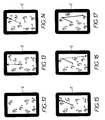
- Les figures 12 à 17 sont des représentations schématiques d'un écran permettant d'illustrer une séquence de tracé d'une route que doit suivre un véhicule tel que, par exemple, un aéronef.
- Figure 1 is a schematic representation of a device according to the invention involving a cursor management terminal shown in vertical axial section;
- Figure 2 is a top view of the terminal shown in Figure 1;
- Figures 3, 4 and 5 are schematic representations of the screen which illustrate different modes of operation of the device;
- Figures 6 and 7 are schematic views in axial section of two alternative embodiments of the terminal;
- FIGS. 8 to 11 are schematic representations of a screen making it possible to illustrate a command sequence for multidirectional scrolling of an image;
- FIGS. 12 to 17 are schematic representations of a screen making it possible to illustrate a sequence of drawing of a route which a vehicle such as, for example, an aircraft must follow.
Dans l'exemple représenté sur la figure 1, le terminal 1 est destiné à assurer la gestion d'un curseur C affiché sur l'écran 2 d'un dispositif d'affichage associé à un processeur 3.In the example shown in FIG. 1, the
Ce terminal comprend un boîtier 4, de forme parallélépipédique dont la face supérieure 5 est munie d'un palier central vertical 6 dans lequel peut pivoter et coulisser axialement un arbre rotatif tubulaire 7.This terminal comprises a
Cet arbre rotatif 7 porte, à son extrémité supérieure, un disque rotatif 8 qui s'étend parallèlement à la face supérieure 5.This
Le maintien en position axiale de l'ensemble arbre 7-disque 8 est assuré par un ressort de compression 9 disposé coaxialement entre la face supérieure 5 et le disque 8.Maintaining the shaft 7-
Le disque 8 comprend, par ailleurs, une cavité centrale coaxiale 11 qui communique avec le volume intérieur de l'arbre tubulaire 7, et dans laquelle est monté coulissant, avec rappel par ressort 12, un poussoir coaxial 13 solidaire d'une tige 14.The
Par ailleurs, le boîtier 4 renferme :
- un
détecteur 15 disposé en regard d'une roue codeuse 16 portée par l'arbre tubulaire 7, coaxialement à celui-ci, - un
micro-interrupteur 17 disposé sous l'arbre tubulaire 7 de manière à être actionné par celui-ci lorsqu'à la suite d'une pression exercée sur ledisque 8l'arbre 7 se déplace vers le bas contre l'action du ressort 9, au-delà d'une course prédéterminée, - un
micro-interrupteur 18 disposé sous l'extrémité de latige 14 qui ressort de l'extrémité inférieure de l'arbre tubulaire 7, de manière à être actionné à la suite d'une pression exercée sur lepoussoir 13, et - une jauge de contrainte optionnelle 19, placée en parallèle ou en remplacement de l'interrupteur 17, de manière à obtenir un signal proportionnel à la force exercée sur le
disque 8.
- a
detector 15 disposed opposite acoding wheel 16 carried by thetubular shaft 7, coaxial with the latter, - a
microswitch 17 placed under thetubular shaft 7 so as to be actuated by the latter when, following a pressure exerted on thedisc 8, theshaft 7 moves down against the action of the spring 9, beyond a predetermined stroke, - a
microswitch 18 disposed under the end of therod 14 which emerges from the lower end of thetubular shaft 7, so as to be actuated following a pressure exerted on thepusher 13, and - an
optional strain gauge 19, placed in parallel with or replacing theswitch 17, so as to obtain a signal proportional to the force exerted on thedisc 8.
Dans cet exemple, la face supérieure 5 du boîtier 4 supporte quatre touches de fonction T₁ à T₄, de forme trapézoïdale, avec la petite base incurvée, qui occupent l'espace compris entre le disque 8 et les bords latéraux du boîtier 4. Ces touches de fonction T₁ à T₄ agissent sur des interrupteurs respectifs 20 montés sur la face supérieure 5.In this example, the upper face 5 of the
La surface cylindrique du disque 8 est munie d'une piste crantée 22 sur laquelle vient porter une bille 23 sollicitée par un ressort 24 en appui sur le boîtier 4, de manière à engendrer une sensation tactile lors de l'entraînement en rotation du disque 8.The cylindrical surface of the
La face supérieure du disque 8 peut être recouverte d'une couche tactile 21 apte à déceler la présence d'un doigt ou d'une main à proximité immédiate du disque 8, voire même un effleurement de ce dernier.The upper face of the
Les interrupteurs 17, 18, 20, le détecteur 15, la jauge de contrainte 19 et la surface tactile 26, sont connectés à un circuit d'interface 27 qui assure une mise en forme des signaux délivrés par ces éléments et les transmet sous une forme numérique appropriée, au processeur 3.The
Tel que précédemment décrit, le terminal 1 permet d'exécuter une multiplicité de fonctions, telles que notamment un déplacement du curseur vers un point à atteindre, avec ou sans visualisation du tracé, le relevé d'un cap et/ou de la distance du curseur à un point singulier, etc...As previously described, the
Lorsque l'opérateur désire déplacer le curseur du point A où il se trouve, vers un point X, il sélecte tout d'abord le mode de fonctionnement correspondant en exerçant une pression sur une touche 20 puis il pose ses doigts sur le disque 8. La couche tactile 26 détecte la présence des doigts et en informe le processeur 3 qui procède alors à l'affichage d'un axe Δ' (en traits interrompus) passant par le centre du curseur C et présentant la dernière orientation donnée à ce dernier. Avantageusement, le curseur pourra présenter la forme d'une flèche colinéaire à l'axe Δ et mobile en rotation avec celui-ci, autour d'un même point (centre 0).When the operator wishes to move the cursor from point A where he is, to point X, he first selects the corresponding operating mode by pressing a key 20 and then places his fingers on the
L'opérateur fait alors pivoter le disque 8, pivotement dont les données angulaires sont transmises au processeur 3 par le détecteur 15 qui, à son tour, provoque un pivotement de l'axe autour du centre 0 (choix de la direction et du sens de déplacement du curseur).The operator then rotates the
Bien entendu, l'opérateur poursuit son pivotement jusqu'à ce que l'axe Δ passe par le point à atteindre X.Of course, the operator continues to pivot until the axis Δ passes through the point to reach X.
L'opérateur exerce alors un appui sur le disque 8 de manière à provoquer une commutation de l'interrupteur 17. Celui-ci émet un signal en direction du processeur 3 qui commande un déplacement du curseur C le long de l'axe Δ, en direction du point X à atteindre.The operator then presses on the
Dans le cas où l'on utilise la jauge de contrainte 19, la vitesse de déplacement du curseur C peut être rendue proportionnelle à l'effort exercé sur le disque 8 (à chaque valeur de l'effort détecté par la jauge 19 peut correspondre une valeur déterminée de la vitesse d'avance).In the case where the
Une fois que le curseur C a atteint le point X recherché, l'opérateur peut appuyer sur le poussoir 13 pour provoquer une commutation de l'interrupteur 18 et, en conséquence, la validation de la position du curseur C. Cette validation peut se traduire par une prise en compte des coordonnées du curseur C par le processeur 3, par une singularisation du point X à l'écran et, éventuellement, par l'effacement de l'axe Δ.Once the cursor C has reached the desired point X, the operator can press the push-
Bien entendu, en sélectionnant un mode graphique, par exemple par une action sur une touche 20, il est possible de visualiser, d'une façon persistante, les déplacements du curseur C. Dans ce cas, ce tracé se maintiendra à la suite de l'effacement de l'axe Δ.Of course, by selecting a graphic mode, for example by pressing a key 20, it is possible to display, in a persistent manner, the movements of the cursor C. In this case, this trace will be maintained following the 'deletion of the axis Δ.
La figure 3, qui illustre le processus précédemment décrit, montre la visualisation à l'écran du trajet du curseur de la position initiale A vers le point X sur l'axe Δ (la direction initiale Δ' de cet axe Δ étant indiquée en traits interrompus).FIG. 3, which illustrates the process described above, shows the visualization on the screen of the path of the cursor from the initial position A to the point X on the Δ axis (the initial direction Δ 'of this Δ axis being indicated by dashed lines).
Toutefois, le mode opératoire utilisé dans cet exemple n'est pas unique : Il serait possible dans un premier temps d'orienter grossièrement l'axe Δ'' comme représenté figure 4 en traits interrompus, puis de procéder ensuite à un ou plusieurs changements de direction pour atteindre le point X.However, the operating mode used in this example is not unique: It would be possible at first to roughly orient the axis Δ '' as shown in Figure 4 in broken lines, then to then make one or more changes of direction to reach point X.
Ce changement de direction peut être effectué en tournant le disque 8, avec ou sans interruption du déplacement du curseur, c'est-à-dire avec ou sans pression sur le disque 8.This change of direction can be carried out by turning the
Il apparaît clairement qu'en combinant la pression et la rotation du disque 8, il est possible d'obtenir des trajets du curseur de forme courbe, voire même circulaire.It clearly appears that by combining the pressure and the rotation of the
A partir du point X, le curseur C peut être amené à un point Y d'une façon analogue à celle précédemment décrite (figure 5).From point X, cursor C can be brought to point Y in a similar way to that previously described (Figure 5).
En raison de ses particularités, le terminal précédemment décrit offre de nombreuses possibilités.Due to its special features, the previously described terminal offers many possibilities.
Il permet, par exemple, de définir le cap que doit suivre le curseur pour parvenir au point recherché ainsi que la distance séparant le curseur de ce point, ces informations pouvant être affichées à l'écran une fois que l'axe lié au curseur a été orienté de manière à passer par ce point et que cette orientation a été validée.It allows, for example, to define the course that the cursor must follow to reach the point sought as well as the distance separating the cursor from this point, this information can be displayed on the screen once the axis linked to the cursor has has been oriented to pass through this point and this orientation has been validated.
Il permet d'effectuer des sélections rapides de plages de commande, disposées par exemple autour de l'écran (par exemple de la façon indiquée en traits interrompus sur la figure 7), en procédant simplement à une orientation de l'axe lié au curseur C de manière à ce qu'il passe par la plage choisie et en validant l'orientation correspondante (sans devoir nécessairement déplacer le curseur le long de l'axe Δ).It allows quick selections of command ranges, for example arranged around the screen (for example as indicated by dashed lines on the Figure 7), by simply orienting the axis linked to the cursor C so that it passes through the chosen range and validating the corresponding orientation (without necessarily having to move the cursor along the axis Δ).
Il permet, en outre, d'incrémenter ou de décrémenter une valeur si le point validé est un compteur.It also allows you to increment or decrement a value if the validated point is a counter.
Bien entendu, l'invention ne se limite pas au mode d'exécution précédemment décrit.Of course, the invention is not limited to the embodiment described above.
Ainsi, le disque 8, muni de sa surface tactile 26, pourrait être porté par un arbre 30 dont la partie inférieure est montée rotative dans un palier 31 tandis que sa partie supérieure, flexible est équipée d'une jauge de contrainte 32 servant à assurer à la fois :
- la détection de l'ordre de déplacement du curseur C,
- la détermination de la vitesse de déplacement du curseur le long de l'axe auquel il se trouve lié.
- the detection of the order of movement of the cursor C,
- determining the speed of movement of the cursor along the axis to which it is linked.
Dans ce cas, la détection de la position angulaire du disque peut s'effectuer à l'aide d'une roue codeuse 33 et d'un détecteur 34.In this case, the angular position of the disc can be detected using an
Selon un autre mode d'exécution illustré sur la figure 7, l'arbre 35 sur lequel est porté le disque 8 comprend une portion sphérique 36 rotulant dans des coquilles de formes complémentaires 37 solidaires du boîtier. L'extrémité inférieure de l'arbre 35 est alors accouplée à une jauge de contrainte 38 assurant à la fois la détection de l'ordre de déplacement du curseur C, la direction de l'axe Δ lié au curseur et la vitesse de déplacement du curseur C. Dans ce cas, l'orientation de l'axe lié au curseur n'est pas obtenue par une rotation du disque 8 mais par un appui sur le disque dans une zone orientée (par rapport au centre du disque) en correspondance avec l'orientation souhaitée de l'axe lié au curseur.According to another embodiment illustrated in FIG. 7, the
Des butées 39, 40 peuvent être prévues de manière à limiter le basculement de l'arbre 35.
Bien entendu, les modes d'exécution représentés sur les figures 6 et 7 pourraient être combinés de manière à pouvoir obtenir une orientation grossière de l'axe Δ en exerçant un appui sur le disque 8 puis en assurant un réglage fin de cette orientation en faisant pivoter le disque 8. Dans ce cas, il suffit d'équiper l'arbre 35 (figure 7) d'une roue codeuse associée à un détecteur correspondant.Of course, the embodiments shown in FIGS. 6 and 7 could be combined so as to be able to obtain a rough orientation of the axis Δ by pressing on the
Comme précédemment mentionné, le procédé selon l'invention peut être utilisé pour commander un défilement multidirectionnel ("scrolling") d'une image représentée partiellement à l'écran.As previously mentioned, the method according to the invention can be used to control a multidirectional scrolling ("scrolling") of an image partially represented on the screen.
Dans ce cas, l'écran est utilisé comme une fenêtre au droit de laquelle l'image peut être déplacée.In this case, the screen is used as a window to the right of which the image can be moved.
L'index est, quant à lui, mobile en rotation autour d'un point fixe par rapport à l'écran.The index is, in turn, mobile in rotation around a fixed point relative to the screen.
Les figures 8 à 11 illustrent un mode opératoire permettant d'effectuer un défilement de l'image en vue de centrer la portion représentée à l'écran sur un objet déterminé.Figures 8 to 11 illustrate a procedure for scrolling the image to center the portion shown on the screen on a specific object.
Dans cet exemple, l'image représente un schéma électrique comprenant un double contact I₁, I₂, et le but du défilement est de disposer ce double contact qui se trouve initialement dans le coin supérieur droit de l'écran (figure 8), au centre de l'écran, comme représenté figure 11.In this example, the image represents an electrical diagram comprising a double contact I₁, I₂, and the purpose of scrolling is to arrange this double contact which is initially located in the upper right corner of the screen (Figure 8), in the center of the screen, as shown in figure 11.
Pour parvenir à ce résultat, dans un premier temps, l'opérateur pose son doigt sur le disque 8.To achieve this result, the operator first places his finger on the
La détection de la présence du doigt par la couche sensible fait alors apparaître, au centre de l'écran, un index de sélection de la direction et du sens de déplacement de l'image (figure 9) qui présente la forme d'une flèche F.The detection of the presence of the finger by the sensitive layer then brings up, in the center of the screen, an index for selecting the direction and the direction of movement of the image (FIG. 9) which has the shape of an arrow. F.
L'opérateur provoque alors une rotation du disque 8 de manière à orienter l'index F selon la direction et le sens du déplacement désirés.The operator then causes a rotation of the
Une fois cette orientation atteinte, un appui sur le disque 8 commande le déplacement du schéma selon la direction et le sens indiqués par l'index F (figure 10) jusqu'à ce que le centrage du double interrupteur I₁, I₂ soit atteint.Once this orientation has been reached, pressing the
En variante, un tel appui pourrait commander le passage du dispositif en mode "déplacement".As a variant, such a support could control the passage of the device in "displacement" mode.
Dans ce cas, une rotation du disque 8 dans le sens des aiguilles d'une montre pourrait commander le déplacement de l'image dans le sens indiqué par l'index F, une rotation dans le sens antihoraire commandant alors le déplacement de l'image dans le sens opposé.In this case, a rotation of the
Le procédé précédemment décrit s'applique particulièrement bien au tracé d'une route jalonnée par des points de passage "way points" prédéfinis.The previously described method applies particularly well to the layout of a route marked out with predefined way points.
Une telle application se trouve illustrée sur les figures 12 à 17 qui représentent un écran sur lequel un ensemble de points de passage P₁ à P₇ sont initialement affichés (figure 12).Such an application is illustrated in FIGS. 12 to 17 which represent a screen on which a set of crossing points P₁ to P₇ are initially displayed (Figure 12).
Pour effectuer le tracé de la route, l'opérateur pose tout d'abord son doigt sur le disque 8 de manière à faire apparaître un index I associé à un axe de balayage Δ₁ (figure 13).To trace the route, the operator first places his finger on the
Dans cet exemple, l'index I se trouve initialement centré sur le point P₃.In this example, the index I is initially centered on the point P₃.
L'opérateur fait alors tourner le disque jusqu'à ce que l'axe de balayage Δ₁ intercepte le premier point désiré (ici, le point P₁ sur la figure 14).The operator then spins the disc until the scanning axis Δ₁ intercepts the first desired point (here, point P₁ in Figure 14).
L'opérateur appuie alors sur le disque 8 pour tracer le tronçon de route ![]()
![]()
L'opérateur effectue ensuite une rotation du disque 8 jusqu'à ce que l'axe Δ₂ associé à l'index I intercepte le deuxième point désiré (ici, le point P₇ sur la figure 15), puis trace le nouveau tronçon de route ![]()
![]()
Ce processus est ensuite répété jusqu'à ce que l'on atteigne le dernier point de passage de la route et qu'on ait tracé le dernier tronçon de la route.This process is then repeated until you reach the last crossing point of the road and have drawn the last section of the road.
Lorsque le tracé de la route (![]()
![]()
![]()
![]()
Claims (23)
caractérisé en ce qu'il comprend un mode de déplacement comportant les étapes suivantes :
characterized in that it comprises a mode of movement comprising the following stages:
caractérisé en ce que la direction que doit emprunter le curseur pour parvenir dans la zone souhaitée de l'image est indiquée par un axe dont le pivotement autour d'un point du curseur est obtenu par la première action de commande manuelle.Method according to claim 1,
characterized in that the direction which the cursor must take to arrive in the desired area of the image is indicated by an axis whose pivoting around a point of the cursor is obtained by the first manual control action.
caractérisé en ce que le curseur présente la forme d'une flèche indiquant un sens de déplacement, et en ce que cette flèche pivote autour de l'un de ses points sous l'effet de la susdite première action de commande.Method according to one of claims 1 and 2,
characterized in that the cursor has the shape of an arrow indicating a direction of movement, and in that this arrow pivots around one of its points under the effect of the above first control action.
caractérisé en ce que la phase de détermination et d'indication à l'écran de la direction et du sens du déplacement relatif que l'on veut réaliser comprend l'affichage d'un axe passant par ledit point de l'index et dont la première action de commande provoque le pivotement autour dudit point.Method according to one of the preceding claims,
characterized in that the phase of determining and indicating on the screen the direction and direction of the relative movement which one wishes to carry out comprises the display of an axis passing through said point of the index and whose first control action causes pivoting around said point.
caractérisé en ce que l'image affichée à l'écran est fixe, et en ce que, dans ce cas, l'index est mobile à la fois en rotation et en translation à la surface de l'écran.Method according to one of the preceding claims,
characterized in that the image displayed on the screen is fixed, and in that in this case the index is movable both in rotation and in translation on the surface of the screen.
caractérisé en ce que la position du point autour duquel pivote l'index est fixe, et en ce que, dans ce cas, l'image est mobile par rapport à l'écran, celui-ci se comportant alors comme une fenêtre en regard de laquelle l'image peut se déplacer selon la direction et le sens indiqués par le curseur.Method according to one of claims 1 to 4,
characterized in that the position of the point around which the index swivels is fixed, and in that in this case the image is movable relative to the screen, the latter then behaving like a window opposite which the image can move in the direction and direction indicated by the cursor.
caractérisé en ce que la susdite première action de commande consiste en l'entraînement en rotation d'un organe de commande rotatif (8) dont le pivotement entraîne celui du curseur et/ou de l'axe affiché à l'écran.Method according to one of the preceding claims,
characterized in that the aforesaid first control action consists in driving in rotation a rotary control member (8) whose pivoting causes that of the cursor and / or of the axis displayed on the screen.
caractérisé en ce que les susdites deuxième et troisième actions consistent en des pressions exercées sur ledit organe de commande (8) de manière à l'entraîner en translation, ces pressions présentant des valeurs respectivement inférieure et supérieure à un seuil de pression prédéterminé.Method according to one of the preceding claims,
characterized in that the aforesaid second and third actions consist of pressures exerted on said control member (8) so as to cause it to translation, these pressures having respectively lower and higher values than a predetermined pressure threshold.
caractérisé en ce que la susdite première action de commande consiste en une pression exercée sur l'organe de commande (8) de manière à provoquer son basculement dans une direction correspondant à celle que doit prendre le susdit axe (Δ).Method according to one of claims 1 to 6,
characterized in that the aforesaid first control action consists of a pressure exerted on the control member (8) so as to cause it to tilt in a direction corresponding to that which the aforesaid axis must take (Δ).
caractérisé en ce que la susdite seconde action consiste à exercer une pression sur ledit organe de commande (8), excédant le susdit seuil.Method according to claim 9,
characterized in that the aforesaid second action consists in exerting a pressure on said control member (8), exceeding the aforementioned threshold.
caractérisé en ce qu'il comprend en outre la détection de la présence du doigt ou de la main, sur ou à proximité de l'organe de commande (8), cette détection provoquant l'affichage du susdit axe (Δ) et/ou de l'index.Method according to one of the preceding claims,
characterized in that it further comprises the detection of the presence of the finger or of the hand, on or near the control member (8), this detection causing the display of the above-mentioned axis (Δ) and / or of the index.
caractérisé en ce qu'il s'applique à la commande d'un défilement multidirectionnel d'une image représentée partiellement à l'écran, et en ce qu'il comprend la sélection de la direction et du sens de déplacement de l'image par la première action de commande et le déplacement de l'image dans la direction et le sens sélectés par la seconde action de commande jusqu'à l'obtention de la position désirée de l'image affichée à l'écran.Method according to one of the preceding claims,
characterized in that it applies to the control of a multidirectional scrolling of an image partially represented on the screen, and in that it comprises the selection of the direction and the direction of movement of the image by the first control action and moving the image in the direction and direction selected by the second control action until the desired position of the image displayed on the screen is obtained.
caractérisé en ce qu'il s'applique au tracé d'une route passant par une pluralité de points de passage (P₁ à P₇) prédéfinis, affichés à l'écran, et en ce qu'il comprend en conséquence :
characterized in that it applies to the layout of a road passing through a plurality of predefined waypoints (P₁ to P₇), displayed on the screen, and in that it consequently comprises:
caractérisé en ce qu'il comprend :
characterized in that it comprises:
caractérisé en ce qu'il comprend en outre des moyens permettant d'afficher à l'écran (E) un axe (Δ) qui s'étend dans la direction indiquée par le curseur (C) et qui pivote de la même façon autour dudit point, ainsi que des moyens permettant d'effacer ledit axe (Δ) à la suite de l'émission du susdit signal de validation.Device according to claim 14,
characterized in that it further comprises means making it possible to display on the screen (E) an axis (Δ) which extends in the direction indicated by the cursor (C) and which pivots in the same way around said point, as well as means making it possible to erase said axis (Δ) following the emission of the above-mentioned validation signal.
caractérisé en ce que le susdit élément de commande (8) consiste en un disque porté par un axe coaxial (7), axialement mobile contre l'action de moyens élastiques (9) et monté pivotant sur une structure fixe (4), et en ce que les moyens de détection de la pression exercée sur l'élément de commande consistent en un interrupteur (17) ou une jauge de contrainte (19) sensible aux déplacements axiaux du susdit arbre (7).Device according to claim 15,
characterized in that the above-mentioned control element (8) consists of a disc carried by a coaxial axis (7), axially movable against the action of elastic means (9) and pivotally mounted on a fixed structure (4), and that the means for detecting the pressure exerted on the control element consist of a switch (17) or a strain gauge (19) sensitive to the axial displacements of the aforesaid shaft (7).
caractérisé en ce que des moyens permettant de détecter la position angulaire du disque (8) consistent en une roue codeuse (16) portée par le susdit arbre (7) et associée à un détecteur (15).Device according to claim 16,
characterized in that means making it possible to detect the angular position of the disc (8) consist of a coding wheel (16) carried by the above-mentioned shaft (7) and associated with a detector (15).
caractérisé en ce que le susdit arbre (7) est tubulaire, et en ce que les susdits moyens aptes à transmettre au processeur (3) un signal de validation comprennent un poussoir (19) monté coulissant avec rappel par ressort (12) dans une cavité centrale coaxiale du disque (8) et qui est solidaire d'une tige (14) axialement coulissante dans ledit arbre (7), cette tige (14) présentant une extrémité dépassant hors de l'axe, qui coopère avec un interrupteur (18).Device according to claim 16,
characterized in that the aforesaid shaft (7) is tubular, and in that the aforesaid means capable of transmitting to the processor (3) a validation signal comprise a pushbutton (19) mounted to slide with spring return (12) in a cavity coaxial central of the disc (8) and which is integral with a rod (14) axially sliding in said shaft (7), this rod (14) having one end projecting off the axis, which cooperates with a switch (18) .
caractérisé en ce qu'il comprend une pluralité de touches (T₁ à T₄) disposées autour de l'élément de commande (8).Device according to one of claims 15 to 18,
characterized in that it comprises a plurality of keys (T₁ to T₄) arranged around the control element (8).
caractérisé en ce que le susdit élément de commande est revêtu d'une couche tactile (26) apte à détecter la présence et/ou le contact d'un doigt de l'opérateur, et à provoquer l'affichage d'un axe (Δ) lié au curseur (C) à la suite d'une détection.Device according to one of claims 15 to 19,
characterized in that the above control element is coated with a tactile layer (26) capable of detecting the presence and / or contact of a finger of the operator, and of causing the display of an axis (Δ ) linked to the cursor (C) following a detection.
caractérisé en ce que le susdit élément de commande (8) est porté par un arbre (30) dont la partie inférieure est montée rotative dans un palier (31) tandis que la partie supérieure, flexible est équipée d'une jauge de contrainte (32) pouvant servir à assurer à la fois :
characterized in that the above control element (8) is carried by a shaft (30), the lower part of which is rotatably mounted in a bearing (31) while the part upper, flexible is equipped with a strain gauge (32) which can be used to ensure both:
caractérisé en ce que le susdit élément de commande (8) est porté par un arbre (35) articulé sur une structure fixe par l'intermédiaire d'une liaison à rotule (36, 37), et en ce que cet arbre (35) est accouplé à une jauge de contrainte (38) assurant à la fois la détection de l'ordre de déplacement du curseur (C), la direction de l'axe (Δ) lié au curseur (C) et la vitesse de déplacement du curseur (C) le long dudit axe (Δ).Device according to claim 15,
characterized in that the above control element (8) is carried by a shaft (35) articulated on a fixed structure by means of a ball joint (36, 37), and in that this shaft (35) is coupled to a strain gauge (38) ensuring both the detection of the order of movement of the cursor (C), the direction of the axis (Δ) linked to the cursor (C) and the speed of movement of the cursor (C) along said axis (Δ).
caractérisé en ce que l'arbre (35) est en outre muni d'une roue codeuse associée à un détecteur.Device according to claim 22,
characterized in that the shaft (35) is further provided with a coding wheel associated with a detector.
Applications Claiming Priority (2)
| Application Number | Priority Date | Filing Date | Title |
|---|---|---|---|
| FR9310550A FR2709578B1 (en) | 1993-09-02 | 1993-09-02 | Method and device for managing the relative movements of a cursor relative to the image displayed on a display device. |
| FR9310550 | 1993-09-02 |
Publications (2)
| Publication Number | Publication Date |
|---|---|
| EP0642075A1 true EP0642075A1 (en) | 1995-03-08 |
| EP0642075B1 EP0642075B1 (en) | 2001-11-07 |
Family
ID=9450568
Family Applications (1)
| Application Number | Title | Priority Date | Filing Date |
|---|---|---|---|
| EP94401877A Expired - Lifetime EP0642075B1 (en) | 1993-09-02 | 1994-08-19 | Method and apparatus for the management of relative displacements of the cursor with respect to the image displayed on the display device |
Country Status (4)
| Country | Link |
|---|---|
| US (1) | US6057826A (en) |
| EP (1) | EP0642075B1 (en) |
| DE (1) | DE69428956D1 (en) |
| FR (1) | FR2709578B1 (en) |
Cited By (1)
| Publication number | Priority date | Publication date | Assignee | Title |
|---|---|---|---|---|
| EP0911750A2 (en) * | 1997-10-23 | 1999-04-28 | Nokia Mobile Phones Ltd. | Input device enabling the control of one or more devices |
Families Citing this family (16)
| Publication number | Priority date | Publication date | Assignee | Title |
|---|---|---|---|---|
| JP2985847B2 (en) * | 1997-10-17 | 1999-12-06 | 日本電気株式会社 | Input device |
| US7046229B1 (en) * | 1999-04-20 | 2006-05-16 | Microsoft Corporation | Computer input device providing absolute and relative positional information |
| US6693653B1 (en) * | 2000-09-19 | 2004-02-17 | Rockwell Collins, Inc. | Method of assisting cursor movement toward a nearby displayed target |
| US7466307B2 (en) * | 2002-04-11 | 2008-12-16 | Synaptics Incorporated | Closed-loop sensor on a solid-state object position detector |
| JP3942028B2 (en) * | 2003-04-15 | 2007-07-11 | 株式会社コナミデジタルエンタテインメント | Cursor control device, cursor control program |
| US20070132733A1 (en) * | 2004-06-08 | 2007-06-14 | Pranil Ram | Computer Apparatus with added functionality |
| US20060288314A1 (en) * | 2005-06-15 | 2006-12-21 | Microsoft Corporation | Facilitating cursor interaction with display objects |
| US8543420B2 (en) * | 2007-09-19 | 2013-09-24 | Fresenius Medical Care Holdings, Inc. | Patient-specific content delivery methods and systems |
| US9395905B2 (en) * | 2006-04-05 | 2016-07-19 | Synaptics Incorporated | Graphical scroll wheel |
| DE102006016898A1 (en) * | 2006-04-11 | 2007-11-15 | Bayerische Motoren Werke Ag | Device for controlling the movement of a cursor |
| US7825797B2 (en) | 2006-06-02 | 2010-11-02 | Synaptics Incorporated | Proximity sensor device and method with adjustment selection tabs |
| US8310446B1 (en) | 2006-08-25 | 2012-11-13 | Rockwell Collins, Inc. | System for integrated coarse and fine graphical object positioning |
| US8698741B1 (en) | 2009-01-16 | 2014-04-15 | Fresenius Medical Care Holdings, Inc. | Methods and apparatus for medical device cursor control and touchpad-based navigation |
| US10799117B2 (en) | 2009-11-05 | 2020-10-13 | Fresenius Medical Care Holdings, Inc. | Patient treatment and monitoring systems and methods with cause inferencing |
| US8632485B2 (en) * | 2009-11-05 | 2014-01-21 | Fresenius Medical Care Holdings, Inc. | Patient treatment and monitoring systems and methods |
| TWI467467B (en) * | 2012-10-29 | 2015-01-01 | Pixart Imaging Inc | Method and apparatus for controlling object movement on screen |
Citations (3)
| Publication number | Priority date | Publication date | Assignee | Title |
|---|---|---|---|---|
| EP0056315A1 (en) * | 1981-01-08 | 1982-07-21 | Atari Inc. | Video game controller |
| US4975689A (en) * | 1987-12-30 | 1990-12-04 | Iwatsu Electric Company, Ltd. | Operation display method and apparatus for variables of an oscilloscope |
| JPH04523A (en) * | 1990-04-17 | 1992-01-06 | Mitsubishi Electric Corp | Mouse device |
Family Cites Families (26)
| Publication number | Priority date | Publication date | Assignee | Title |
|---|---|---|---|---|
| FR1587030A (en) * | 1968-10-22 | 1970-03-06 | Commissariat Energie Atomique | TELEMEASUREMENT PROCESS AND EQUIPMENT BY APPLYING |
| US3643148A (en) * | 1970-04-16 | 1972-02-15 | Edo Corp | Ball tracker assembly |
| US4313113A (en) * | 1980-03-24 | 1982-01-26 | Xerox Corporation | Cursor control |
| JPS59173804A (en) * | 1983-03-23 | 1984-10-02 | Fanuc Ltd | Automatic programming method |
| US4550221A (en) * | 1983-10-07 | 1985-10-29 | Scott Mabusth | Touch sensitive control device |
| US4680577A (en) * | 1983-11-28 | 1987-07-14 | Tektronix, Inc. | Multipurpose cursor control keyswitch |
| DE3475661D1 (en) * | 1984-09-12 | 1989-01-19 | Ibm | Automatic highlighting in a raster graphics display system |
| US4812829A (en) * | 1986-05-17 | 1989-03-14 | Hitachi, Ltd. | Three-dimensional display device and method for pointing displayed three-dimensional image |
| EP0265534B1 (en) * | 1986-10-25 | 1989-03-08 | Hewlett-Packard GmbH | Device to control the movement of a picture screen cursor |
| US4763100A (en) * | 1987-08-13 | 1988-08-09 | Wood Lawson A | Joystick with additional degree of control |
| US4853630A (en) * | 1987-08-28 | 1989-08-01 | Houston John S | Magnetic position sensor having spaced toroidal magnets in a state of equilibrium |
| US5191641A (en) * | 1988-09-26 | 1993-03-02 | Sharp Kabushiki Kaisha | Cursor shift speed control system |
| US5327161A (en) * | 1989-08-09 | 1994-07-05 | Microtouch Systems, Inc. | System and method for emulating a mouse input device with a touchpad input device |
| JP2736149B2 (en) * | 1990-03-23 | 1998-04-02 | 株式会社東芝 | Trend graph scaling device |
| JPH0751625Y2 (en) * | 1990-06-18 | 1995-11-22 | 京セラ株式会社 | Joystick |
| US5299307A (en) * | 1990-08-17 | 1994-03-29 | Claris Corporation | Controls for drawing images on computer displays |
| JPH04160622A (en) * | 1990-10-25 | 1992-06-03 | Mutoh Ind Ltd | Input device for cad |
| DE4034166A1 (en) * | 1990-10-26 | 1992-04-30 | Cherry Mikroschalter Gmbh | Position control of screen cursor - has input element that can be moved, in X-Y plane with spring return to neutral position |
| US5278557A (en) * | 1991-02-19 | 1994-01-11 | Key Tronic Corporation | Cursor movement control key and electronic computer keyboard for computers having a video display |
| JP2558984B2 (en) * | 1991-03-12 | 1996-11-27 | 松下電器産業株式会社 | 3D information conversation system |
| FR2677149B1 (en) * | 1991-05-27 | 1994-02-04 | Sextant Avionique | METHOD AND DEVICE FOR REVIEWING THE LATERAL FLIGHT PLAN OF AN AERODYNE. |
| US5414801A (en) * | 1991-06-11 | 1995-05-09 | Virtus Corporation | Computerized method and apparatus using containment relationships to represent objects in a three-dimensional space, and for moving therethrough |
| US5235868A (en) * | 1991-10-02 | 1993-08-17 | Culver Craig F | Mechanism for generating control signals |
| JPH05233141A (en) * | 1992-02-25 | 1993-09-10 | Mitsubishi Electric Corp | Pointing device |
| US5453758A (en) * | 1992-07-31 | 1995-09-26 | Sony Corporation | Input apparatus |
| FI92111C (en) * | 1992-12-11 | 1994-09-26 | Icl Personal Systems Oy | Method and arrangement for moving the cursor on a computer screen |
-
1993
- 1993-09-02 FR FR9310550A patent/FR2709578B1/en not_active Expired - Fee Related
-
1994
- 1994-08-19 EP EP94401877A patent/EP0642075B1/en not_active Expired - Lifetime
- 1994-08-19 DE DE69428956T patent/DE69428956D1/en not_active Expired - Lifetime
-
1996
- 1996-04-18 US US08/781,176 patent/US6057826A/en not_active Expired - Fee Related
Patent Citations (3)
| Publication number | Priority date | Publication date | Assignee | Title |
|---|---|---|---|---|
| EP0056315A1 (en) * | 1981-01-08 | 1982-07-21 | Atari Inc. | Video game controller |
| US4975689A (en) * | 1987-12-30 | 1990-12-04 | Iwatsu Electric Company, Ltd. | Operation display method and apparatus for variables of an oscilloscope |
| JPH04523A (en) * | 1990-04-17 | 1992-01-06 | Mitsubishi Electric Corp | Mouse device |
Non-Patent Citations (1)
| Title |
|---|
| PATENT ABSTRACTS OF JAPAN vol. 016, no. 139 (P - 1334) 8 April 1992 (1992-04-08) * |
Cited By (2)
| Publication number | Priority date | Publication date | Assignee | Title |
|---|---|---|---|---|
| EP0911750A2 (en) * | 1997-10-23 | 1999-04-28 | Nokia Mobile Phones Ltd. | Input device enabling the control of one or more devices |
| EP0911750A3 (en) * | 1997-10-23 | 2006-01-04 | Nokia Corporation | Input device enabling the control of one or more devices |
Also Published As
| Publication number | Publication date |
|---|---|
| EP0642075B1 (en) | 2001-11-07 |
| US6057826A (en) | 2000-05-02 |
| DE69428956D1 (en) | 2001-12-13 |
| FR2709578B1 (en) | 1995-11-17 |
| FR2709578A1 (en) | 1995-03-10 |
Similar Documents
| Publication | Publication Date | Title |
|---|---|---|
| EP0635858B1 (en) | Joystick | |
| EP0642075B1 (en) | Method and apparatus for the management of relative displacements of the cursor with respect to the image displayed on the display device | |
| FR2686440A1 (en) | DEVICE FOR MULTIMODE MANAGEMENT OF A CURSOR ON THE SCREEN OF A DISPLAY DEVICE. | |
| EP0293291B1 (en) | Remote control device for a computer associated with a display screen | |
| EP0903684B1 (en) | Computer input device with automatic switching between 3D and 2D operating modes, and method for interaction with a display screen | |
| FR2899719A1 (en) | ELECTRICAL SWITCH WITH MULTIPLE SWITCHES | |
| EP1241436A1 (en) | Coordinate measuring machine and method for introducing a command to change the measurement mode in this machine | |
| EP1666833B1 (en) | Motorised and orientable measuring head | |
| FR2851347A1 (en) | Man-machine interface device for use in vehicle control panel, has touch screen moved with respect to case by actuator based on displacement patterns controlled by analysis and treatment unit to produce touch differential effects | |
| EP2204719A1 (en) | Joystick comprising Hall sensor and production process | |
| JP4502810B2 (en) | Method for selecting an operation element for an electronic device for operating a sensor and a function included in an electronic memory and displaying the selected function with a cursor | |
| US20060284831A1 (en) | Optical input device with a rotatable surface | |
| EP1617172B1 (en) | Steerable feeler head | |
| FR2814849A1 (en) | MULTIAXIS POTENTIOMETER, PROGRAM AND RELATED METHOD | |
| FR2634922A1 (en) | METHOD FOR ROTATING AROUND AN AXIS OF AN OBJECT DISPLAYED IN 3D REPRESENTATION USING A 2D INPUT CONTROLLER SUCH AS A MOUSE | |
| KR20120041137A (en) | User-interface for controlling a data processing system using a joystick | |
| EP1720092A1 (en) | Hybrid isotonic/elastic input peripheral | |
| EP0720082A1 (en) | Process for producing and modifying a design on the visual display screen of a terminal | |
| FR3005516A1 (en) | CONFIGURABLE MAN-MACHINE INTERFACE | |
| FR2728986A1 (en) | METHOD FOR CONTROLLING A PROCESS USING A TERMINAL | |
| FR2760863A1 (en) | PUBLIC INFORMATION TERMINAL | |
| FR3035981A1 (en) | ROTARY SWITCH AGENCY ON A SCREEN | |
| FR2680899A1 (en) | Device for controlling the motion of a mobile body in a field of motion | |
| EP0725361B1 (en) | Control device suitable for pointing and moving of an object on a screen | |
| EP1634648A1 (en) | Pipette comprising a command equipment and a mobile piston equipment |
Legal Events
| Date | Code | Title | Description |
|---|---|---|---|
| PUAI | Public reference made under article 153(3) epc to a published international application that has entered the european phase |
Free format text: ORIGINAL CODE: 0009012 |
|
| 17P | Request for examination filed |
Effective date: 19940830 |
|
| AK | Designated contracting states |
Kind code of ref document: A1 Designated state(s): DE GB IT NL |
|
| 17Q | First examination report despatched |
Effective date: 20000627 |
|
| GRAG | Despatch of communication of intention to grant |
Free format text: ORIGINAL CODE: EPIDOS AGRA |
|
| GRAG | Despatch of communication of intention to grant |
Free format text: ORIGINAL CODE: EPIDOS AGRA |
|
| GRAH | Despatch of communication of intention to grant a patent |
Free format text: ORIGINAL CODE: EPIDOS IGRA |
|
| GRAH | Despatch of communication of intention to grant a patent |
Free format text: ORIGINAL CODE: EPIDOS IGRA |
|
| GRAA | (expected) grant |
Free format text: ORIGINAL CODE: 0009210 |
|
| AK | Designated contracting states |
Kind code of ref document: B1 Designated state(s): DE GB IT NL |
|
| PG25 | Lapsed in a contracting state [announced via postgrant information from national office to epo] |
Ref country code: NL Free format text: LAPSE BECAUSE OF FAILURE TO SUBMIT A TRANSLATION OF THE DESCRIPTION OR TO PAY THE FEE WITHIN THE PRESCRIBED TIME-LIMIT Effective date: 20011107 Ref country code: IT Free format text: LAPSE BECAUSE OF FAILURE TO SUBMIT A TRANSLATION OF THE DESCRIPTION OR TO PAY THE FEE WITHIN THE PRESCRIBED TIME-LIMIT;WARNING: LAPSES OF ITALIAN PATENTS WITH EFFECTIVE DATE BEFORE 2007 MAY HAVE OCCURRED AT ANY TIME BEFORE 2007. THE CORRECT EFFECTIVE DATE MAY BE DIFFERENT FROM THE ONE RECORDED. Effective date: 20011107 |
|
| REF | Corresponds to: |
Ref document number: 69428956 Country of ref document: DE Date of ref document: 20011213 |
|
| REG | Reference to a national code |
Ref country code: GB Ref legal event code: IF02 |
|
| GBT | Gb: translation of ep patent filed (gb section 77(6)(a)/1977) |
Effective date: 20020110 |
|
| PG25 | Lapsed in a contracting state [announced via postgrant information from national office to epo] |
Ref country code: DE Free format text: LAPSE BECAUSE OF FAILURE TO SUBMIT A TRANSLATION OF THE DESCRIPTION OR TO PAY THE FEE WITHIN THE PRESCRIBED TIME-LIMIT Effective date: 20020208 |
|
| NLV1 | Nl: lapsed or annulled due to failure to fulfill the requirements of art. 29p and 29m of the patents act | ||
| PG25 | Lapsed in a contracting state [announced via postgrant information from national office to epo] |
Ref country code: GB Free format text: LAPSE BECAUSE OF NON-PAYMENT OF DUE FEES Effective date: 20020819 |
|
| PLBE | No opposition filed within time limit |
Free format text: ORIGINAL CODE: 0009261 |
|
| STAA | Information on the status of an ep patent application or granted ep patent |
Free format text: STATUS: NO OPPOSITION FILED WITHIN TIME LIMIT |
|
| 26N | No opposition filed | ||
| GBPC | Gb: european patent ceased through non-payment of renewal fee |
Effective date: 20020819 |