EP0642000A2 - Method for drift elimination in sensors - Google Patents
Method for drift elimination in sensors Download PDFInfo
- Publication number
- EP0642000A2 EP0642000A2 EP94202293A EP94202293A EP0642000A2 EP 0642000 A2 EP0642000 A2 EP 0642000A2 EP 94202293 A EP94202293 A EP 94202293A EP 94202293 A EP94202293 A EP 94202293A EP 0642000 A2 EP0642000 A2 EP 0642000A2
- Authority
- EP
- European Patent Office
- Prior art keywords
- sensor
- medium
- flow
- alternating
- drift
- Prior art date
- Legal status (The legal status is an assumption and is not a legal conclusion. Google has not performed a legal analysis and makes no representation as to the accuracy of the status listed.)
- Granted
Links
Images

Classifications
-
- G—PHYSICS
- G01—MEASURING; TESTING
- G01F—MEASURING VOLUME, VOLUME FLOW, MASS FLOW OR LIQUID LEVEL; METERING BY VOLUME
- G01F1/00—Measuring the volume flow or mass flow of fluid or fluent solid material wherein the fluid passes through a meter in a continuous flow
- G01F1/68—Measuring the volume flow or mass flow of fluid or fluent solid material wherein the fluid passes through a meter in a continuous flow by using thermal effects
- G01F1/684—Structural arrangements; Mounting of elements, e.g. in relation to fluid flow
-
- G—PHYSICS
- G01—MEASURING; TESTING
- G01F—MEASURING VOLUME, VOLUME FLOW, MASS FLOW OR LIQUID LEVEL; METERING BY VOLUME
- G01F25/00—Testing or calibration of apparatus for measuring volume, volume flow or liquid level or for metering by volume
- G01F25/10—Testing or calibration of apparatus for measuring volume, volume flow or liquid level or for metering by volume of flowmeters
Definitions
- the invention provides a method for the elimination of drift in vector sensors.
- a vector sensor is understood to be measuring a physical vectorial quantity S in an input energy domain D i by converting S into a signal in an output energy domain D o .
- electric or electronic sensors for the measurement of gas flow or pressure.
- sensors are seen to simultaneously possess a state A in the input energy domain D i and a state B in the output energy domain D o .
- the new method of operation concerns the real-world application of sensors in the presence of imperfections. Imperfections are generally present in both the sensor itself and, in the case of active sensors, in the biasing of the sensor and its output amplifiers. While ideal sensors as abstract devices possess zero sensitivity for physical quantities other than S , sensors in the real-world possess imperfections due to technological limitations and, consequently, possess finite sensitivity for quantities other than S . Errors in the measurement of S due to finite sensitivity to quantities other than S are manifested in the form of offset with unpredictable behavior. The resulting drift in offset persists additively as drift in the output signal, when the input signal, S , is kept constant.
- the resulting offset is predominant over noise, i.e ., S /offset, ⁇ S /noise, so that offset defines the lowest limit at which S can be reliably measured.
- offset typically determines the dynamic range of the sensor at hand, rather than noise.
- the new method is proposed for elimination of drift.
- the method applies to sensors with directional sensitivity, i.e. , anisotropic sensitivity in two or more directions. Sensors of this type are also known as vector sensors. Sensors with this property define an orientation with respect to which S is measured.
- the new method eliminates drift by taking the difference of two measurements which are made by the same sensor in succession with different sensor states A in the input energy domain D i .
- the two different sensor states A can be realized through two different relative orientations between sensor and medium.
- the forementioned two successive measurements, from which the drift-free measurement is obtained are obtained with successively different relative orientations of the sensor with respect to the medium, which relative orientations are precisely those that possess different sensitivities to the physical quantity S .
- the new method which we shall refer to as the Alternating Direction Method (ADM)
- the drift-free measurements are obtained from the difference between successive measurement results by the sensor when measuring with alternating relative orientations between sensor and medium.
- the power of ADM can be exemplified in gas volume measurement using the flow sensor as described in forementioned U.S. patents.
- this sensor is bidirectional in the sense that the sign of the electric output signal due to the flow velocity S changes with rotation of the sensor over 90° or 180° (as described in forementioned U.S. patents 4,548,077 and 3,996,799, and in U.S. patent application 127424 by M.H.P.M. van Putten) relative to the flow direction.
- asymmetries occur on the order of a few percent.
- a realistic measurement therefore, represents not only the temperature gradient over the sensor, that is, the bidirectional signal, but contains a component as a function of the total dissipation as well.
- ADM volume is now given by with ADM remainder
- ADM eliminates, therefore, undesired contributions due to drift in offset in gas volume measurement up to a remainder in the order of 2 ⁇ tV drift .
- the ADM remainder is independent of total time of integration, and only depends on the interval time, ⁇ t , of each measurement with either of the alternating directions.
- Figure 1 shows an implementation of a gas volume meter, in which the two different relative orientations between sensor S and medium are obtained through successively changing the flow direction of the medium as it passes through a measurement section M with fixed sensor holder H.
- a gas flow switching unit is used which alternates the direction of the gas flow using two flow switches, SL and SR.
- the flow switches SL and SR are operated via the control inputs CL and CR, respectively.
- Counter clockwise (clockwise) flow is obtained by opening L1 (L2) and R1 (R2) for gas flow entering HL and HR, respectively, with L2 (L1) and R2 (R1) in closed position.
- Gas flow counter clockwise is obtained via the T-elements TL and TR, which connect the measurement section M with the switches SL and SR, respectively.
- Gas flow clockwise is obtained through the two connections BL and BR, connections between the T-elements TL and TR, which are connected to the measurement section M, and switches SR and SL, respectively.
- FIG. 2 shows an implementation of a gas flow meter, in which the two different relative orientations between sensor and flow medium are obtained by alternatingly setting the sensor in two different positions in a measurement section M with fixed flow direction (from the left to the right in Figure 2).
- a rotational unit, D is used, in which the sensor holder H, as in Figure 1, now changes position alternatingly by 180° from Position 1 (2) to Position 2 (1).
- the rotational unit D is operated via control input CD.
- the flow switch SL(SR) is a standard pneumatic switch, such as those used for pneumatic control in industry.
- the switch SL(SR) possesses three opening pipes for gas flow: with two positions SL(SR) connects either the pipe opening HL(HR) with pipe opening L1(R1) or HL(HR) with pipe opening L2(R2).
- the switch is operated via control input CL(CR), either pneumatically or electrically, depending on the switch used.
- the pipe openings L1 and R1 are each connected to a T-pipe elements TL and TR, respectively.
- the pipe openings L2 and R2 are each connected to pipes BL and BR, respectively, which are in turn connected to forementioned T-elements TR and TL, respectively.
- the three pipe openings in each of the switches SL and SR, the pipes BL and BR, and the T-elements TL and TR all have inner diameters preferably, though not necessarily, sufficiently large to ensure flow through-put with a low amount of friction (at the expected flow rate), and therefore a low amount of pressure drop across the apparatus as measured over the input HL at the input pipe of switch SL and the output HR at the output pipe of switch SR.
- the pipes BL, BR and T-elements TL, TL are made of durable material, either flexible or rigid, such as plastic or metal.
- the measuring section M is made of a pipe with inner diameter sufficiently large to allow uninhibited flow over the holder H with sensor S.
- the sensor S may be the silicon flow sensor as described in U.S. patent 4,548,077, or any other sensor with allows for 180° directional sensitivity.
- the sensor is mounted on a holder H, which is made out of thermally insulating material with electrical connections on it for interconnection between the sensor
- the measuring section is made of a pipe with inner diameter sufficiently large to allow uninhibited flow through-put (at the expected flow rate), with preferably low amount of pressure drop across the input at the left and the output at the right.
- the measuring section M contains the switching unit D in order to alternatingly rotate the holder H with sensor S, as described in Figure 1, in two positions 1 and 2.
- the switching unit is operated via control input CD, which drives the holder H in either of the two positions 1 and 2.
- the switching unit D is an electromechanical device, containing an electrical motor to drive the holder H, with electrical control CD.
- the switching unit D could be constructed as a purely mechanical device with mechanical or pneumatic control CD.
- the switching unit enables the holder H to rotate over 180°, while providing electrical connection between the rotating holder H and the outside world.
- the holder H contains the electrical connections to the sensor S.
- the electrical connections between the rotating holder H and the outside world is made possible by using flexible cable.
- alternative means for electrical connection between the rotating holder H and the outside world could be used.
- the techniques used for electrical connection between rotating cylindrical heads in magnetic video recorder apparatus could be used as an alternative to using a flexible cable, in order to provide for the electrical connection between the holder H and the outside world.
- the measuring section M act as a shield for external influences.
- section M act as a shield, because upon alternating between positions 1 and 2, as prescribed by ADM, external influences for which the sensor S is sensitive, can contribute to the ADM signal in case the external influences act with different intensities on the sensor in each of the two positions 1 and 2.
- the section M is made preferably of non-transparent material so as to avoid influences of external light should the sensor S be light sensitive, something which is typical for semi-conductor sensors.
Landscapes
- Physics & Mathematics (AREA)
- Fluid Mechanics (AREA)
- General Physics & Mathematics (AREA)
- Indicating Or Recording The Presence, Absence, Or Direction Of Movement (AREA)
- Measuring Volume Flow (AREA)
Abstract
Description
- The invention provides a method for the elimination of drift in vector sensors. To set notation, a vector sensor is understood to be measuring a physical vectorial quantity S in an input energy domain D i by converting S into a signal in an output energy domain D o . In particular, we think here of electric or electronic sensors for the measurement of gas flow or pressure. Thus, sensors are seen to simultaneously possess a state A in the input energy domain D i and a state B in the output energy domain D o .
- The new method of operation concerns the real-world application of sensors in the presence of imperfections. Imperfections are generally present in both the sensor itself and, in the case of active sensors, in the biasing of the sensor and its output amplifiers. While ideal sensors as abstract devices possess zero sensitivity for physical quantities other than S, sensors in the real-world possess imperfections due to technological limitations and, consequently, possess finite sensitivity for quantities other than S. Errors in the measurement of S due to finite sensitivity to quantities other than S are manifested in the form of offset with unpredictable behavior. The resulting drift in offset persists additively as drift in the output signal, when the input signal, S, is kept constant. Typically, the resulting offset is predominant over noise, i.e., S/offset,<< S/noise, so that offset defines the lowest limit at which S can be reliably measured. In other words, offset typically determines the dynamic range of the sensor at hand, rather than noise. We remark that drift in the sensitivity of a sensor to its measurand S does not influence the dynamic range of the sensor. For this reason, only the forementioned drift in offset, i.e., additive drift is considered here.
- The current approach towards elimination of drift is taken by a continuous effort towards ever more precise manufacturing processes. In particular, modern manufacturing processes involve special correction techniques such as laser trimming, with which imperfections resulting from the basic production process are greatly reduced. In such approach, the final performance of the sensor is determined by the quality of the overall production process. With our new method, proposed below, technological limitations are of secondary importance.
- The new method is proposed for elimination of drift. The method applies to sensors with directional sensitivity, i.e., anisotropic sensitivity in two or more directions. Sensors of this type are also known as vector sensors. Sensors with this property define an orientation with respect to which S is measured.
- An example of a vector sensor is given by the flow sensor by A.F.P. van Putten (U.S. patent 4,548,077 and 3,996,799), where the gas flow velocity, S, induces a thermal gradient (a vectorial quantity) in a silicon integrated chip. This silicon flow sensor is heated electrically, and obtains temperature gradients in the presence of gas flow. An integrated Wheatstone bridge reads off the temperature gradient induced by such flow.
- The new method eliminates drift by taking the difference of two measurements which are made by the same sensor in succession with different sensor states A in the input energy domain D i . In the presence of directional sensitivity the two different sensor states A can be realized through two different relative orientations between sensor and medium. Thus, in the new method the forementioned two successive measurements, from which the drift-free measurement is obtained, are obtained with successively different relative orientations of the sensor with respect to the medium, which relative orientations are precisely those that possess different sensitivities to the physical quantity S. In the new method, which we shall refer to as the Alternating Direction Method (ADM), the drift-free measurements are obtained from the difference between successive measurement results by the sensor when measuring with alternating relative orientations between sensor and medium. We shall refer to the output signal thus obtained as the ADM signal. We conclude that a sensor which discriminates between S and quantities other than S which may interfere with the measurement of S, in the sense that the sensor possesses forementioned directional sensitivity to S, while its sensitivity is independent of direction to quantities other than S which may interfere with measurement of S, offers an ADM signal which contains no drift.
- The power of ADM can be exemplified in gas volume measurement using the flow sensor as described in forementioned U.S. patents. As an abstract device this sensor is bidirectional in the sense that the sign of the electric output signal due to the flow velocity S changes with rotation of the sensor over 90° or 180° (as described in forementioned U.S. patents 4,548,077 and 3,996,799, and in U.S. patent application 127424 by M.H.P.M. van Putten) relative to the flow direction. In the manufacturing process of these sensors asymmetries occur on the order of a few percent. A realistic measurement, therefore, represents not only the temperature gradient over the sensor, that is, the bidirectional signal, but contains a component as a function of the total dissipation as well. Drift in the offset as a function of temperature, humidity, age etc., deteriorates the measurement signal in practice mainly through a change in the total dissipation, and, consequently, is independent of relative orientation between sensor and flow medium (a common mode signal in the flow medium). The said bidirectional flow sensor, therefore, offers the unique possibility for elimination of drift in offset through application of ADM. This may be made more precise in gas volume measurement as follows.
- In gas volume measurement with ADM we integrate the electric output signal of the sensor, V, as induced by the flow velocity S, over consecutive time intervals


Here, we have written the output signal as it is composed of the pure V flow and the undesired drift, V drift . The ADM volume,
is now given by
with ADM remainder
The ADM remainder has the property that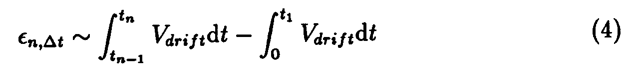
in the limit as
- Application of ADM in gas flow measurement is illustrated by the following two implementations.
First possible implementation. Figure 1 shows an implementation of a gas volume meter, in which the two different relative orientations between sensor S and medium are obtained through successively changing the flow direction of the medium as it passes through a measurement section M with fixed sensor holder H. To this end, a gas flow switching unit is used which alternates the direction of the gas flow using two flow switches, SL and SR. The flow switches SL and SR are operated via the control inputs CL and CR, respectively. Counter clockwise (clockwise) flow is obtained by opening L1 (L2) and R1 (R2) for gas flow entering HL and HR, respectively, with L2 (L1) and R2 (R1) in closed position. Gas flow counter clockwise is obtained via the T-elements TL and TR, which connect the measurement section M with the switches SL and SR, respectively. Gas flow clockwise is obtained through the two connections BL and BR, connections between the T-elements TL and TR, which are connected to the measurement section M, and switches SR and SL, respectively. - Operation of this flow switching set-up alternatingly clockwise and counter clockwise results in two relative orientations between sensor and flow medium which differ by 180°.
- ADM can now be applied to the sensor as described in forementioned U.S. patents with 180° bidirectional sensitivity, by taking the difference between every two successive measurements with different relative orientations between sensor and medium obtained through alternatingly clockwise and counter clockwise flow directions.
Second possible implementation. Figure 2 shows an implementation of a gas flow meter, in which the two different relative orientations between sensor and flow medium are obtained by alternatingly setting the sensor in two different positions in a measurement section M with fixed flow direction (from the left to the right in Figure 2). To this end, a rotational unit, D, is used, in which the sensor holder H, as in Figure 1, now changes position alternatingly by 180° from Position 1 (2) to Position 2 (1). The rotational unit D is operated via control input CD. With forementioned installation of the sensor ADM can now be applied, by taking the difference between measurements with positions alternatingly in 1 and 2, such as indicated in the 'boxed' subfigure. - Tests have shown that with ADM the forementioned flow sensor yields a dynamic range up to three decades of flow velocity, from 1cms⁻¹ to 10ms⁻¹ in the presence of reproducibility better than 1%. With this new method of operation, measurements are made possible which go beyond those feasible with current techniques (other than laser-doppler flow metering techniques).
- Referring more specifically to the drawings, for illustrative purposes the present invention is embodied in each of the two apparatus generally shown in Figure 1 and Figure 2. It will be appreciated that the embodiment of the invention may vary as to the particular sensor and as to the details of the parts without departing from the basic concepts as disclosed herein.
- Referring to Figure 1, the flow switch SL(SR) is a standard pneumatic switch, such as those used for pneumatic control in industry. The switch SL(SR) possesses three opening pipes for gas flow: with two positions SL(SR) connects either the pipe opening HL(HR) with pipe opening L1(R1) or HL(HR) with pipe opening L2(R2). The switch is operated via control input CL(CR), either pneumatically or electrically, depending on the switch used. The pipe openings L1 and R1 are each connected to a T-pipe elements TL and TR, respectively. The pipe openings L2 and R2 are each connected to pipes BL and BR, respectively, which are in turn connected to forementioned T-elements TR and TL, respectively.
- The three pipe openings in each of the switches SL and SR, the pipes BL and BR, and the T-elements TL and TR all have inner diameters preferably, though not necessarily, sufficiently large to ensure flow through-put with a low amount of friction (at the expected flow rate), and therefore a low amount of pressure drop across the apparatus as measured over the input HL at the input pipe of switch SL and the output HR at the output pipe of switch SR. The pipes BL, BR and T-elements TL, TL are made of durable material, either flexible or rigid, such as plastic or metal. The measuring section M is made of a pipe with inner diameter sufficiently large to allow uninhibited flow over the holder H with sensor S. The sensor S may be the silicon flow sensor as described in U.S. patent 4,548,077, or any other sensor with allows for 180° directional sensitivity. The sensor is mounted on a holder H, which is made out of thermally insulating material with electrical connections on it for interconnection between the sensor itself and the outside world.
- Referring to Figure 2, the measuring section is made of a pipe with inner diameter sufficiently large to allow uninhibited flow through-put (at the expected flow rate), with preferably low amount of pressure drop across the input at the left and the output at the right. The measuring section M contains the switching unit D in order to alternatingly rotate the holder H with sensor S, as described in Figure 1, in two
positions positions - In each of the embodiments as shown in Figure 1 and 2, it is preferable to have the measuring section M act as a shield for external influences. In the embodiment in Figure 2, it is of particular importance to have section M act as a shield, because upon alternating between
positions positions - Although the description above is in the context of flow measurement, this presentation should not be construed as limiting the applicability of ADM but merely as providing illustration of a real-world application of ADM. Thus, the scope of ADM should be determined by the appended claims and their legal equivalents.
Claims (4)
- Method of measurement of a physical quantity S in a given medium by employment of a sensor whose sensitivity to S possesses directional dependence. The method has the property that drift in the measurement is eliminated by means of alternating the orientation of the sensor and the medium with respect to each other, said alternating orientations being associated with alternatingly different sensitivities of said sensor to S, and taking the difference between the alternating sensor measurements of S, said alternating sensor measurements being associated with said alternatingly different orientations.
- Method of operation such as stated in Claim 1 with the property that the two relative orientations between sensor and medium are obtained by alternating the orientation of said medium (with physical quantity S), while keeping the orientation of said sensor fixed.
- Method of operation such as stated in Claim 1 with the property the two relative orientations between sensor and medium are obtained by alternating the position of the sensor in the medium (with physical quantity S), while keeping the orientation of said medium fixed.
- Method of operation such as stated in Claim 1 where the medium is a vacuum, and where the alternatingly different relative orientations between sensor and medium are obtained by alternating the orientation of said sensor with respect to the distant stars.
Applications Claiming Priority (4)
| Application Number | Priority Date | Filing Date | Title |
|---|---|---|---|
| NL9301399A NL9301399A (en) | 1993-08-12 | 1993-08-12 | Drift elimination with sensors. |
| NL9301399 | 1993-08-12 | ||
| US199538 | 1994-02-22 | ||
| US08/199,538 US5426969A (en) | 1993-08-12 | 1994-02-22 | Method for drift elimination in sensors |
Publications (4)
| Publication Number | Publication Date |
|---|---|
| EP0642000A2 true EP0642000A2 (en) | 1995-03-08 |
| EP0642000A3 EP0642000A3 (en) | 1997-01-29 |
| EP0642000B1 EP0642000B1 (en) | 2002-02-27 |
| EP0642000B9 EP0642000B9 (en) | 2002-04-17 |
Family
ID=26647124
Family Applications (1)
| Application Number | Title | Priority Date | Filing Date |
|---|---|---|---|
| EP94202293A Expired - Lifetime EP0642000B9 (en) | 1993-08-12 | 1994-08-10 | Method for drift elimination in sensors |
Country Status (2)
| Country | Link |
|---|---|
| EP (1) | EP0642000B9 (en) |
| DE (1) | DE69429954T2 (en) |
Cited By (1)
| Publication number | Priority date | Publication date | Assignee | Title |
|---|---|---|---|---|
| WO2006014537A1 (en) | 2004-07-08 | 2006-02-09 | Celerity, Inc. | Attitude insensitive flow device system and method |
Families Citing this family (1)
| Publication number | Priority date | Publication date | Assignee | Title |
|---|---|---|---|---|
| US7409871B2 (en) | 2006-03-16 | 2008-08-12 | Celerity, Inc. | Mass flow meter or controller with inclination sensor |
Citations (2)
| Publication number | Priority date | Publication date | Assignee | Title |
|---|---|---|---|---|
| JPS61288110A (en) * | 1985-06-14 | 1986-12-18 | Yokogawa Electric Corp | Optical fiber gyro device |
| WO1991005985A1 (en) * | 1989-10-17 | 1991-05-02 | Wedge Innovations, Inc. | Rescaleable inclinometer |
-
1994
- 1994-08-10 DE DE69429954T patent/DE69429954T2/en not_active Expired - Fee Related
- 1994-08-10 EP EP94202293A patent/EP0642000B9/en not_active Expired - Lifetime
Patent Citations (2)
| Publication number | Priority date | Publication date | Assignee | Title |
|---|---|---|---|---|
| JPS61288110A (en) * | 1985-06-14 | 1986-12-18 | Yokogawa Electric Corp | Optical fiber gyro device |
| WO1991005985A1 (en) * | 1989-10-17 | 1991-05-02 | Wedge Innovations, Inc. | Rescaleable inclinometer |
Non-Patent Citations (1)
| Title |
|---|
| PATENT ABSTRACTS OF JAPAN vol. 011, no. 153 (P-577), 19 May 1987 & JP-A-61 288110 (YOKOGAWA ELECTRIC CORP), 18 December 1986, * |
Cited By (3)
| Publication number | Priority date | Publication date | Assignee | Title |
|---|---|---|---|---|
| WO2006014537A1 (en) | 2004-07-08 | 2006-02-09 | Celerity, Inc. | Attitude insensitive flow device system and method |
| EP1766340A1 (en) * | 2004-07-08 | 2007-03-28 | Entegris, Inc. | Attitude insensitive flow device system and method |
| EP1766340A4 (en) * | 2004-07-08 | 2007-07-11 | Entegris Inc | Attitude insensitive flow device system and method |
Also Published As
| Publication number | Publication date |
|---|---|
| EP0642000B1 (en) | 2002-02-27 |
| DE69429954D1 (en) | 2002-04-04 |
| EP0642000B9 (en) | 2002-04-17 |
| DE69429954T2 (en) | 2002-11-14 |
| EP0642000A3 (en) | 1997-01-29 |
Similar Documents
| Publication | Publication Date | Title |
|---|---|---|
| US4283679A (en) | Rotational direction detection device for a motor or the like | |
| US4092852A (en) | Multiplexed transducer | |
| GB2197483A (en) | Determining rotational speed using magnetic sensors | |
| JP2003519372A (en) | Magnetoresistive position detector | |
| US7130750B1 (en) | Flow meter with magnetoresistive sensors and method of measuring flow | |
| EP0863382B1 (en) | Device for driving stepping motor-type instrument | |
| CN117168530A (en) | Self-calibration method of magnetic encoder, magnetic encoder and motor | |
| EP0642000B1 (en) | Method for drift elimination in sensors | |
| KR20040028664A (en) | Liquid level sensor device | |
| US4339943A (en) | Pressure transducer cross-check system | |
| US5426969A (en) | Method for drift elimination in sensors | |
| JPS6130770A (en) | Vehicle detector | |
| EP0672245B1 (en) | Humidity measuring instrument | |
| JPH06310776A (en) | Magnetic detection element having failure detecting function | |
| CN101529264A (en) | Sensor | |
| US2595881A (en) | Compensated thermometer | |
| SU1151842A1 (en) | Pressure measuring device and method of calibrating thereof | |
| JP3061111B2 (en) | Dimension measuring device | |
| SU958910A1 (en) | Viscometer | |
| JPH09232647A (en) | Hall element diving circuit | |
| SU1352180A1 (en) | Two-channel follow-up displacement meter | |
| KR19980061593A (en) | Tuning Gyro Temperature Control Circuit Using AD590 and Darlington Transistor | |
| JPS63313007A (en) | Measuring instrument for axial elongation quantity of rotary body | |
| JPH0677558A (en) | Magnetic sensor | |
| SU1339417A1 (en) | Pressure gauge |
Legal Events
| Date | Code | Title | Description |
|---|---|---|---|
| PUAI | Public reference made under article 153(3) epc to a published international application that has entered the european phase |
Free format text: ORIGINAL CODE: 0009012 |
|
| AK | Designated contracting states |
Kind code of ref document: A2 Designated state(s): DE FR GB NL |
|
| K1C1 | Correction of patent application (title page) published |
Effective date: 19950308 |
|
| RAP1 | Party data changed (applicant data changed or rights of an application transferred) |
Owner name: VAN PUTTEN, PASCAL F.A.M. Owner name: VAN PUTTEN, ANTONIUS F.P. Owner name: VAN PUTTEN, MICHAEL J.A.M. Owner name: VAN PUTTEN, MAURITIUS H.P.M. |
|
| PUAL | Search report despatched |
Free format text: ORIGINAL CODE: 0009013 |
|
| RHK1 | Main classification (correction) |
Ipc: G01F 15/02 |
|
| AK | Designated contracting states |
Kind code of ref document: A3 Designated state(s): DE FR GB NL |
|
| 17P | Request for examination filed |
Effective date: 19970725 |
|
| 17Q | First examination report despatched |
Effective date: 20000608 |
|
| GRAG | Despatch of communication of intention to grant |
Free format text: ORIGINAL CODE: EPIDOS AGRA |
|
| GRAG | Despatch of communication of intention to grant |
Free format text: ORIGINAL CODE: EPIDOS AGRA |
|
| GRAH | Despatch of communication of intention to grant a patent |
Free format text: ORIGINAL CODE: EPIDOS IGRA |
|
| GRAH | Despatch of communication of intention to grant a patent |
Free format text: ORIGINAL CODE: EPIDOS IGRA |
|
| REG | Reference to a national code |
Ref country code: GB Ref legal event code: IF02 |
|
| GRAA | (expected) grant |
Free format text: ORIGINAL CODE: 0009210 |
|
| AK | Designated contracting states |
Kind code of ref document: B1 Designated state(s): DE FR GB NL |
|
| REF | Corresponds to: |
Ref document number: 69429954 Country of ref document: DE Date of ref document: 20020404 |
|
| ET | Fr: translation filed | ||
| PGFP | Annual fee paid to national office [announced via postgrant information from national office to epo] |
Ref country code: DE Payment date: 20020822 Year of fee payment: 9 |
|
| PGFP | Annual fee paid to national office [announced via postgrant information from national office to epo] |
Ref country code: FR Payment date: 20020826 Year of fee payment: 9 |
|
| PGFP | Annual fee paid to national office [announced via postgrant information from national office to epo] |
Ref country code: GB Payment date: 20020827 Year of fee payment: 9 |
|
| PGFP | Annual fee paid to national office [announced via postgrant information from national office to epo] |
Ref country code: NL Payment date: 20020830 Year of fee payment: 9 |
|
| PLBE | No opposition filed within time limit |
Free format text: ORIGINAL CODE: 0009261 |
|
| STAA | Information on the status of an ep patent application or granted ep patent |
Free format text: STATUS: NO OPPOSITION FILED WITHIN TIME LIMIT |
|
| 26N | No opposition filed |
Effective date: 20021128 |
|
| PG25 | Lapsed in a contracting state [announced via postgrant information from national office to epo] |
Ref country code: GB Free format text: LAPSE BECAUSE OF NON-PAYMENT OF DUE FEES Effective date: 20030810 |
|
| PG25 | Lapsed in a contracting state [announced via postgrant information from national office to epo] |
Ref country code: NL Free format text: LAPSE BECAUSE OF NON-PAYMENT OF DUE FEES Effective date: 20040301 |
|
| PG25 | Lapsed in a contracting state [announced via postgrant information from national office to epo] |
Ref country code: DE Free format text: LAPSE BECAUSE OF NON-PAYMENT OF DUE FEES Effective date: 20040302 |
|
| GBPC | Gb: european patent ceased through non-payment of renewal fee |
Effective date: 20030810 |
|
| PG25 | Lapsed in a contracting state [announced via postgrant information from national office to epo] |
Ref country code: FR Free format text: LAPSE BECAUSE OF NON-PAYMENT OF DUE FEES Effective date: 20040430 |
|
| NLV4 | Nl: lapsed or anulled due to non-payment of the annual fee |
Effective date: 20040301 |
|
| REG | Reference to a national code |
Ref country code: FR Ref legal event code: ST |