EP0641981A1 - Spray-freeze slush hydrogen generator - Google Patents
Spray-freeze slush hydrogen generator Download PDFInfo
- Publication number
- EP0641981A1 EP0641981A1 EP94113240A EP94113240A EP0641981A1 EP 0641981 A1 EP0641981 A1 EP 0641981A1 EP 94113240 A EP94113240 A EP 94113240A EP 94113240 A EP94113240 A EP 94113240A EP 0641981 A1 EP0641981 A1 EP 0641981A1
- Authority
- EP
- European Patent Office
- Prior art keywords
- tank
- slush
- hydrogen
- slush hydrogen
- vacuum
- Prior art date
- Legal status (The legal status is an assumption and is not a legal conclusion. Google has not performed a legal analysis and makes no representation as to the accuracy of the status listed.)
- Granted
Links
- 239000001257 hydrogen Substances 0.000 title claims abstract description 136
- 229910052739 hydrogen Inorganic materials 0.000 title claims abstract description 136
- UFHFLCQGNIYNRP-UHFFFAOYSA-N Hydrogen Chemical compound [H][H] UFHFLCQGNIYNRP-UHFFFAOYSA-N 0.000 title claims abstract description 126
- 239000007787 solid Substances 0.000 claims abstract description 58
- 239000007788 liquid Substances 0.000 claims abstract description 49
- 239000007921 spray Substances 0.000 claims abstract description 13
- 238000001704 evaporation Methods 0.000 claims abstract description 11
- 150000002431 hydrogen Chemical class 0.000 claims abstract description 10
- 238000010924 continuous production Methods 0.000 claims abstract description 5
- 239000002245 particle Substances 0.000 claims description 11
- 239000000203 mixture Substances 0.000 claims description 9
- 238000005507 spraying Methods 0.000 claims description 9
- 238000005086 pumping Methods 0.000 claims description 7
- 238000002156 mixing Methods 0.000 claims description 3
- 238000001914 filtration Methods 0.000 claims description 2
- 238000004519 manufacturing process Methods 0.000 description 26
- 238000000034 method Methods 0.000 description 14
- 239000012530 fluid Substances 0.000 description 9
- 239000000446 fuel Substances 0.000 description 8
- 238000012423 maintenance Methods 0.000 description 8
- 230000008569 process Effects 0.000 description 7
- 230000000694 effects Effects 0.000 description 6
- 230000008020 evaporation Effects 0.000 description 6
- 238000002844 melting Methods 0.000 description 5
- 230000008018 melting Effects 0.000 description 5
- 238000012856 packing Methods 0.000 description 3
- 238000003860 storage Methods 0.000 description 3
- 238000012360 testing method Methods 0.000 description 3
- 230000009471 action Effects 0.000 description 2
- 230000015572 biosynthetic process Effects 0.000 description 2
- 238000009835 boiling Methods 0.000 description 2
- 238000001816 cooling Methods 0.000 description 2
- 239000007789 gas Substances 0.000 description 2
- 239000008240 homogeneous mixture Substances 0.000 description 2
- 238000009413 insulation Methods 0.000 description 2
- 239000003380 propellant Substances 0.000 description 2
- 230000009467 reduction Effects 0.000 description 2
- 230000004044 response Effects 0.000 description 2
- 238000012424 Freeze-thaw process Methods 0.000 description 1
- 230000032683 aging Effects 0.000 description 1
- 239000012080 ambient air Substances 0.000 description 1
- 230000001186 cumulative effect Effects 0.000 description 1
- 238000001739 density measurement Methods 0.000 description 1
- 238000013461 design Methods 0.000 description 1
- 238000011161 development Methods 0.000 description 1
- 230000018109 developmental process Effects 0.000 description 1
- 238000010586 diagram Methods 0.000 description 1
- 230000003292 diminished effect Effects 0.000 description 1
- 239000012467 final product Substances 0.000 description 1
- 230000009969 flowable effect Effects 0.000 description 1
- 239000006260 foam Substances 0.000 description 1
- 238000007710 freezing Methods 0.000 description 1
- 230000008014 freezing Effects 0.000 description 1
- 230000006872 improvement Effects 0.000 description 1
- 238000010348 incorporation Methods 0.000 description 1
- 238000005259 measurement Methods 0.000 description 1
- 238000012986 modification Methods 0.000 description 1
- 230000004048 modification Effects 0.000 description 1
- 239000000047 product Substances 0.000 description 1
- 230000003134 recirculating effect Effects 0.000 description 1
- 238000005057 refrigeration Methods 0.000 description 1
- 238000012958 reprocessing Methods 0.000 description 1
- 238000011160 research Methods 0.000 description 1
- 229920006395 saturated elastomer Polymers 0.000 description 1
- 238000000926 separation method Methods 0.000 description 1
Images

Classifications
-
- B—PERFORMING OPERATIONS; TRANSPORTING
- B64—AIRCRAFT; AVIATION; COSMONAUTICS
- B64G—COSMONAUTICS; VEHICLES OR EQUIPMENT THEREFOR
- B64G1/00—Cosmonautic vehicles
- B64G1/22—Parts of, or equipment specially adapted for fitting in or to, cosmonautic vehicles
- B64G1/40—Arrangements or adaptations of propulsion systems
- B64G1/402—Propellant tanks; Feeding propellants
-
- F—MECHANICAL ENGINEERING; LIGHTING; HEATING; WEAPONS; BLASTING
- F25—REFRIGERATION OR COOLING; COMBINED HEATING AND REFRIGERATION SYSTEMS; HEAT PUMP SYSTEMS; MANUFACTURE OR STORAGE OF ICE; LIQUEFACTION SOLIDIFICATION OF GASES
- F25J—LIQUEFACTION, SOLIDIFICATION OR SEPARATION OF GASES OR GASEOUS OR LIQUEFIED GASEOUS MIXTURES BY PRESSURE AND COLD TREATMENT OR BY BRINGING THEM INTO THE SUPERCRITICAL STATE
- F25J1/00—Processes or apparatus for liquefying or solidifying gases or gaseous mixtures
- F25J1/0002—Processes or apparatus for liquefying or solidifying gases or gaseous mixtures characterised by the fluid to be liquefied
- F25J1/0005—Light or noble gases
- F25J1/001—Hydrogen
-
- F—MECHANICAL ENGINEERING; LIGHTING; HEATING; WEAPONS; BLASTING
- F25—REFRIGERATION OR COOLING; COMBINED HEATING AND REFRIGERATION SYSTEMS; HEAT PUMP SYSTEMS; MANUFACTURE OR STORAGE OF ICE; LIQUEFACTION SOLIDIFICATION OF GASES
- F25J—LIQUEFACTION, SOLIDIFICATION OR SEPARATION OF GASES OR GASEOUS OR LIQUEFIED GASEOUS MIXTURES BY PRESSURE AND COLD TREATMENT OR BY BRINGING THEM INTO THE SUPERCRITICAL STATE
- F25J1/00—Processes or apparatus for liquefying or solidifying gases or gaseous mixtures
- F25J1/02—Processes or apparatus for liquefying or solidifying gases or gaseous mixtures requiring the use of refrigeration, e.g. of helium or hydrogen ; Details and kind of the refrigeration system used; Integration with other units or processes; Controlling aspects of the process
- F25J1/0243—Start-up or control of the process; Details of the apparatus used; Details of the refrigerant compression system used
- F25J1/0257—Construction and layout of liquefaction equipments, e.g. valves, machines
- F25J1/0275—Construction and layout of liquefaction equipments, e.g. valves, machines adapted for special use of the liquefaction unit, e.g. portable or transportable devices
- F25J1/0276—Laboratory or other miniature devices
-
- F—MECHANICAL ENGINEERING; LIGHTING; HEATING; WEAPONS; BLASTING
- F25—REFRIGERATION OR COOLING; COMBINED HEATING AND REFRIGERATION SYSTEMS; HEAT PUMP SYSTEMS; MANUFACTURE OR STORAGE OF ICE; LIQUEFACTION SOLIDIFICATION OF GASES
- F25J—LIQUEFACTION, SOLIDIFICATION OR SEPARATION OF GASES OR GASEOUS OR LIQUEFIED GASEOUS MIXTURES BY PRESSURE AND COLD TREATMENT OR BY BRINGING THEM INTO THE SUPERCRITICAL STATE
- F25J2205/00—Processes or apparatus using other separation and/or other processing means
- F25J2205/20—Processes or apparatus using other separation and/or other processing means using solidification of components
-
- F—MECHANICAL ENGINEERING; LIGHTING; HEATING; WEAPONS; BLASTING
- F25—REFRIGERATION OR COOLING; COMBINED HEATING AND REFRIGERATION SYSTEMS; HEAT PUMP SYSTEMS; MANUFACTURE OR STORAGE OF ICE; LIQUEFACTION SOLIDIFICATION OF GASES
- F25J—LIQUEFACTION, SOLIDIFICATION OR SEPARATION OF GASES OR GASEOUS OR LIQUEFIED GASEOUS MIXTURES BY PRESSURE AND COLD TREATMENT OR BY BRINGING THEM INTO THE SUPERCRITICAL STATE
- F25J2290/00—Other details not covered by groups F25J2200/00 - F25J2280/00
- F25J2290/42—Modularity, pre-fabrication of modules, assembling and erection, horizontal layout, i.e. plot plan, and vertical arrangement of parts of the cryogenic unit, e.g. of the cold box
Abstract
Description
- The present invention relates to processes and apparatus for producing slush hydrogen, and more particularly to a method and apparatus for continuously producing slush hydrogen at a significantly higher rate of production than those now known in the prior art to permit reduction In the size of the slush generator required to support an aerospace vehicle of the type powered by slush fuels.
- One of the principal objectives of aerospace research today is to develop a long range, hypersonic space vehicle which can journey from the earth to various points in outer space. Recently, vehicles of this type have originated from work under the National AeroSpace Plane (NASP) program. Some of the requirements of these vehicles include high density, low volume fuel; high speed travel (hypersonic range); relative light weight; and relatively large payloads. Fuels for these vehicles which have been considered include slush fuels, such as slush hydrogen.
- The production of slush hydrogen (SH2) is currently accomplished by means of a "freeze/thaw" process. For the freeze/thaw process, the pressure in a container of liquid hydrogen (LH2) is progressively reduced by a vacuum pump. The resulting evaporation of hydrogen reduces the bulk temperature to the saturation temperature corresponding to the ullage pressure. The ullage pressure will be reduced to the triple-point (T.P.) pressure of 1.02 PSIA.
- After the triple-point pressure is reached, further evaporation of hydrogen will convert part of the triple-point liquid to solid hydrogen. If the pressure is continuously maintained at the triple-point pressure, the frozen hydrogen will form as a solid sheet at the surface and ultimately suppress any further freezing action. Removing vapor at a low rate is also conducive to forming a solid sheet at the surface. Removing vapor at a high rate causes violent boiling and eruption of the bulk hydrogen, resulting in a large carry-over of liquid hydrogen droplets with the vapor flow.
- Tests performed in the 1960's at the Bureau of Standards Cryogenics Laboratory showed that the optimum vapor withdrawal rate to minimize liquid hydrogen carry-over was approximately 160 CFM of vapor per square foot of liquid surface area. This flow rate was referenced to the vacuum pump inlet, and the inlet vapor had to be heated (approx. 500° R, 40°F) because of vacuum pump mechanical limitations. The corresponding volumetric withdrawal rate at the liquid surface (approx. 24.8 R) was less by a factor of approximately 20, or 8 CFM per square foot of surface area.
- To eliminate the formation of a solid sheet of hydrogen at the surface, the vacuum level is cycled above and below the triple-point pressure. During this portion of the cycle (about 1/2 the time) when the pressure is above the triple-point, the incoming heat (heat leaks and/or warm pressurant) causes part of the solid hydrogen at the surface to melt. Since solid hydrogen is more dense than liquid hydrogen, the former sinks in the remaining liquid. A mixer (propeller) in the bulk liquid assists in breaking up the solid hydrogen and in producing a more homogeneous mixture of the slush hydrogen.
- The above-described process constitutes, for the most part, the currently-used freeze/thaw slush hydrogen production process. This process, as presently practiced, is a batch-type operation, and the slush production rate is relatively slow. Typically, slush is produced only 50% of the time and a significant portion (about 30%) of just-formed slush is melted in the thaw cycle.
- For example, the slush generator at the Slush Test Facility at Martin Marietta Corporation produces slush at the equivalent rate of approximately 9 gallons per minute (GPM). For a vehicle using slush hydrogen as its fuel (e.g., a NASP-type vehicle), the required slush generation rate during the density-maintenance operation is expected to be in the range of 1000 GPM to 4000 GPM, depending on the actual heat load to the propellant during the loading operation. It can be readily seen that a substantial improvement in slush production rate must be achieved if slush hydrogen is to be used to fuel a NASP-type vehicle.
- It is therefore a principal object of the present invention to provide apparatus and a method of producing slush hydrogen at a substantially higher rate than the rate of production currently known possible, while overcoming all the disadvantages and drawbacks of known like apparatus and methods.
- It is another object of the present invention to provide apparatus and a method for the continuous production of slush hydrogen in quantities which will facilitate its use as a fuel for a NASP-type vehicle.
- Still another object of the invention is to provide a system for the continuous, high volume production of a near-homogeneous slush hydrogen mixture having a solid particle size that allows for the attainment of a desired solid fraction in NASP vehicle tanks.
- Still another object of the invention is to provide a method and a system for the continuous, high volume production of a near-homogeneous slush hydrogen mixture of a sufficient fluidity to permit transport through ground and vehicle lines and valves.
- Yet another object of the invention is to provide a method and apparatus for generating a continuous, uninterrupted flow of gaseous hydrogen to support a self-contained power system, especially one which is embodied as a mobile, ground support unit.
-
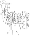
- Figure 1 is a schematic diagram of a slush generator according to the teachings of the present invention; and
- Figure 2 is a schematic view of an alternate embodiment of a solid-vapor separator assembly for use with the slush generator of the present invention.
- Referring now to Figure 1 , there is schematically shown the
slush generator apparatus 10 of the present invention which has the capability of producing slush hydrogen at a rate great enough to fulfill the slush hydrogen maintenance requirements of a NASP-sized vehicle. Theslush generator apparatus 10 has been designed for incorporation into the slush maintenance system described in applicant's co-pending application U.S. Serial No. 07/950,522 filed September 25, 1992. - The pressure (i.e., the vacuum) in the
tank 100 of the slush generator apparatus is produced by avacuum pump 20 which is driven by aturbine 22. The vacuum pump is preferably a high-speed, cold vapor pump of the axial or radial type, and the turbine is driven by hot gas from any of a variety of hot gas generators. - Liquid hydrogen from a triple-
point catch tank 210 is introduced into theslush hydrogen tank 100 throughline 212 under the control of avalve 214 to a primary spray ring 216 (discussed in greater detail below). - Operation of the
control valve 214 may be automatic, as for example, in response to signals from alevel sensor 102 located on the surface of the liquid component of the slush mixture inside the generator. Such automatic control would serve the purpose of maintaining the fluid level in the slush generator approximately constant at the level sensor location. - The liquid hydrogen from the triple-
point catch tank 210 is transported throughpipe 212 to thespray ring 216 where it is sprayed into the slush hydrogen generator. The purpose of the spray is to increase the "area" of exposure of the liquid hydrogen to facilitate its evaporation. - In an evaporative-cooling slush production process, the solid hydrogen production rate is solely a function of the mass flow rate of vapor removed from the liquid hydrogen when at the triple-point temperature. Prior attempts, such of those of the Bureau of Standards (described above), have been made to manufacture slush hydrogen by spraying liquid hydrogen into an evacuated container. In those prior tests, the liquid hydrogen flow was kept at a very low value relative to the capacity of the vacuum pump.
- As a consequence, the final product was 100% solid hydrogen (snow), which settled in drifts around the tank and required partial melting before a flowable slush mixture was obtained. This result led the Bureau of Standards researchers to abandon the spray-freeze concept in favor of the freeze-thaw process. That decision has influenced the design of all actual or proposed slush hydrogen production facilities until the innovation embodied in the present application.
- In the present invention, the solid hydrogen production rate is also determined by the capacity of the vacuum system. The vacuum pump is sized to produce a mass flow rate of vapor at the triple point pressure (1.02 psia) such that the solid hydrogen production rate is equal to or greater than the required production rate. In a flight vehicle slush maintenance system, the solid hydrogen production rate would be determined by the solid hydrogen melting rate resulting from the airborne and ground systems heat loads to the slush. For a facility storage tank loading, the solid production rate would be a function of the desired, or available, time to load the tank.
- The present invention is distinguished over previously developed spray-freeze slush generators in that the incoming mass flow rate of LH2 exceeds the solid production rate as determined by the vacuum pump capacity.
- If the incoming LH2 is at the triple-point temperature, the solid production rate will be constant at the maximum value determined by the vacuum pump capacity. By adjusting the incoming flow rate of triple-point LH2, the composition of the product can be varied from 100% solids (snow) to slush with a very low solid fraction, all with the same solid hydrogen content. For incoming LH2 warmer than the triple-point temperature, the production rate of solid hydrogen will be diminished in direct proportion to the fraction of the vacuum pump capacity that is required to evaporatively cool the incoming LH2 to the triple point temperature.
- As noted previously, if the spray-freeze slush generator is used in a vehicle slush density maintenance system, the vacuum pump capacity would be based on the solid hydrogen melting rate resulting from the cumulative heat loads in the airborne and ground systems. The output of the slush generator is slush hydrogen at a volumetric flow rate and solid fraction such that solid hydrogen is added to the vehicle system at the same rate at which solid hydrogen is melting. The total mass flow rate of maintenance fluid is returned to the
catch tank 210, where it is available to be re-introdcued into the slush generator for reprocessing back to slush hydrogen. - Hydrogen lost through evaporation in the refrigeration process must be replaced by liquid hydrogen to maintain a constant fluid mass in the vehicle and slush generator circuit. Under equilibrium conditions, the total system is essentially self-adjusting to provide the proper solid fraction at the required flow rate. As will be discussed later, provisions have been made to "fine tune" the effective capacity of the vacuum pump to more precisely match the solid hydrogen production rate with the solid hydrogen melting rate. Also discussed later are means to adjust the output solid fraction to minimize the volumetric flow rate of slush required to provide the required mass flow rate of solid hydrogen to the vehicle.
- Essential differences between the present invention and the currently known freeze-thaw concept are that (1) the production of slush hydrogen in the present invention is continuous, and (2) the discharge of gaseous hydrogen in the present invention is continuous. These features are essential to a practicla slush maintenance unit, and to the operation of a power system utilizing gaseous hydrogen as a fuel, respectively.
- With the upward flow of vapor in the slush generator, there is a tendency for the solid and/or liquid particles to be blown into the vacuum pump. To minimize this effect, the cross-sectional area of the
shoulder 112 of the slush generator above the spray rings should be made as large as practicable to reduce the upward velocity of vapor. To further assure as little loss of liquids or solids as possible through the vacuum pump, acentrifugal separator 200 is mounted downstream of theneck 114 of the slush generator. Theseparator 200 includes aflat plate 202 having a plurality of radially extendingslots 206 formed therein and a set of flaps or louvers 204 displaced from the plane of the flat plate at an angle thereto and adjacent the slots. The flaps of theseparator 200 function to deflect or slap solid or liquid particles away from the slots, and allow only vapor to pass through. - The
plate 202 of theseparator 200 is supported on a vertically orientedshaft 208 which is rotatably coupled to the drive of amotor 210 mounted in the neck of the slush generator. - Figure 2 shows an
alternate embodiment 200' of the separator, which includes a motor 210' a shaft 208' rotatably coupled between the drive of the motor and a first plate 202' The first plate includes a plurality of slots 206' preferably disposed radially about the plate. The first plate 202' forms the top of a cylinder or drum 220' which includes a solid bottom 222', a plurality of louvers or flaps 226' secured to the vertical supports 224' so that the flaps are arranged substantially perpendicular to the first and second plates. - The invention contemplates various other similar arrangements of centrifugal separators, the purpose of all of which is to eliminate large losses of solid or liquid hydrogen. However, a small loss of liquid or solids would have a negligible effect on the overall production rate of the slush generator, and could even yield a desirable result by reducing the power requirement for the vacuum pump by cooling the vapor as it passes through the pump.
- Referring again to Figure 1, a
centrifugal pump 120 located at the bottom of the slush generator draws slush from the bottom of the generator tank and increases the fluid pressure for transfering the slush to the vehicle propellant tanks or to a facility storage tank. Inasmuch as the solid particles formed by the spray evaporation process tend to be large and fluffy, the fluidity of slush hydrogen at the desired solid fraction may not be sufficient to permit pumping and movement through the slush transport lines. To eliminate this problem, mixer orblender blades 122 are provided above thepump 120 in the bottom of the generator tank. These blades have a configuration similar to those in a typical household blender, and are incorporated into, and driven by themotor 124 of, the pump. Alternatively, the mixer or blender could be driven by a separate, dedicated motor. The blades are provided with relatively sharp leading edges with alternate positive and negative angles of attack, and function to reduce the particle size to enhance packing and to produce a more homogeneous mixture of the fluid as it enters the pump. The bottom of thegenerator tank 100 is conical to assure that all of the pumped fluid passes through the mixer blades. The action of the mixer blades creates an enhanced packing effect that is currently produced by "aging" of the newly-formed slush. - The slush hydrogen output flow is controlled by a modulating
valve 130. This valve can be controlled in response to signals from a vehicle loading control system. The density (solid fraction) of the pump discharge is monitored by an in-line density sensor 140. If the measured density is lower than desired, part of the triple point liquid hydrogen portion of the slush hydrogen can be stripped from the flow and returned to the slush generator through thepipe 142. The stripping of triple point liquid hydrogen is accomplished using a solid-liquid separator 150 comprising a simple flow-reversing fluid device for causing the heavier solid particles to separate from the lighter liquid. The liquid flow is reintroduced into the slush generator through a plurality of appropriately sized apertures in therecirculatory spray ring 110, and part of this liquid is ultimately converted to a solid state. Since the flow into thetank 100 throughvalve 214 is controlled by thelevel sensor 102, recirculation of liquid hydrogen from the solid-liquid separator reduces the volumetric outflow of fluid from the tank, thereby causing a corresponding reduction in the flow rate through thevalve 214. - The effect of recirculating LH2 through
pipe 142 is to increase the solid fraction of solid hydrogen delivered through thevalve 130. An alternative to returning the recirculated LH2 throughspray ring 110 is to introduce all or part of it through the mixingring 104. The liquid introduced through thering 104 serves as an added mixer for the slush intank 100. In addition, the heat added to the recirculated LH2 by thepump 120 serves to melt small protrusions on the solid hydrogen particles, thereby enabling a higher packing density withintank 100. The division of flow through thepipe 142 is controlled by modulatingvalves - While optimum separation efficiency of solid-
liquid separator 150 is desired, some small fraction of solids in the recirc lines is acceptable as long as the orifices in the rings are sized to accommodate whatever solids are entrained. No problem is envisioned, since the mixer blades should produce small particles. Also, a lage particle is less likely to reverse direction and be entrained in the recirculation flow. - The final output slush density is measured by in-
line density sensor 160. In practice, the measurement at thesensor 160 will be used as the input signal to control thevalves venturi flow meter 170 in conjunction with the density measurement fromsensor 160 can be used to calculate the mass flow rate of slush hydrogen being delivered to a vehicle tank for slush density maintenance, or to a facility storage tank. - The slush generation rate can be varied by modulating
valve 300, which creates a pressure drop and thereby has the effect of reducing the vapor withdrawal rate from the slush generator tank. An alternate method of generation rate control is to modulatevalve 400 via thecheck valve 402. The backflow throughvalve 400 will also have the effect of reducing the vapor withdrawal rate. By opening upvalve 400 wide, the pressure in the generator tank can be increased to be in excess of 1.02 PSIA, whereupon solid formation will cease. The compressively-heated vapor will serve a defrost or thaw function in the event accumulated solids obstruct the flow passages of the solid/vapor separator. - Line 420 carries the hydrogen vapor drawn off the LH2 in
tank 100 by thevacuum pump 20 during the manufacture of SH2. The discharged hydrogen can be used in the power system (which is the preferred use) or just dumped into a burn stack for disposal. - The slush genetator tank must be well-insulated to avoid excessive heat input to the slush hydrogen and/or the liquefaction of ambient air on the exterior of the tank. All lines and valves must be similarly insulated. Foam insulation 500 may be used on development units. The ultimate unit will preferably employ a vacuum-jacketed tank and lines with multi-layer insulation to reduce the input heat to an absolute minimum.
- The slush generator as described herein can also be used for the basic facility slush plant for preparing and accumulating slush hydrogen for the initial vehicle loading. The only difference is that free-boiling (F.B.) liquid hydrogen, saturated at the local ambient pressure, would be introduced through
valve 214 instead of triple-point (T.P.) LH2. The slush production rate would be reduced by virtue of the fact that additional evaporation is required to convert the F.B. liquid hydrogen to triple point (T.P.) liquid hydrogen before any solids are formed. - While certain representative embodiments and details have been shown for the purpose of illustrating the invention, it will be apparent to those skilled in this art that various changes and modifications may be made therein without departing from the spirit or scope of this invention.
- The invention may be summarized as follows:
- 1. A high rate, continuous production, slush hydrogen generator, comprising:
a tank,
means for creating a vacuum in said tank,
means for delivering triple point (T.P.) liquid hydrogen (LH2) to said tank,
means, interacting with said vacuum in said tank, for producing slush hydrogen with a substantially constant solid fraction from said T.P. LH2, and
means for delivering cold vapors from said tank to said vacuum creating means. - 2. The slush hydrogen generator , wherein said producing means comprises means for evaporating said triple point liquid hydrogen.
- 3. The slush hydrogen generator , wherein said evaporating means comprises a perforated spray ring and means for delivering said liquid hydrogen under pressure to said spray ring.
- 4. The slush hydrogen generator , wherein said vacuum creating means comprises a vacuum pump fluidly coupled with said tank.
- 5. The slush hydrogen generator wherein said vacuum pump is driven by a turbine and is fluidly communicated, via ducting, with said cold vapors in said tank.
- 6. The slush hydrogen generator , wherein said ducing includes means for filtering solid particles from said vapors.
- 7. The slush hydrogen generator and further including sensors in said ducting for controlling operation of said vacuum creating means.
- 8. The slush hydrogen generator and further including means for removing a desired amount of slush hydrogen from said tank for delivery to a point of use.
- 9. The slush hydrogen generator , wherein said removing means comprises pumping means for drawing slush hydrogen from said tank, said pumping means communicating with a lower region of said tank.
- 10. The slush hydrogen generator , and further including means for returning a portion of the liquid hydrogen component, removed as slush hydrogen from said tank, back to said tank.
- 11. The slush hydrogen generator wherein said portion returning means includes means for spraying said liquid hydrogen into said vacuum in said tank.
- 12. The slush hydrogen generator , wherein said portion returning means includes means for injecting said liquid hydrogen into said slush hydrogen in said tank.
- 13. The slush hydrogen generator wherein said injecting means comprises a perforated mixing ring located within said tank below the surface of said slush hydrogen mixture.
- 14. The slush hydrogen generator , wherein said spraying means comprises a perforated ring member disposed above the surface of said slush hydrogen mixture.
- 15. The slush hydrogen generator , wherein said spraying means and said injecting means are fluidly coupled.
- 16. The slush hydrogen generator , wherein said spraying means and said injecting means are fluidly coupled with said pumping means.
Claims (10)
- A high rate, continuous production, slush hydrogen generator, comprising:
a tank,
means for creating a vacuum in said tank,
means for delivering triple point (T.P.) liquid hydrogen (LH2) to said tank,
means, interacting with said vacuum in said tank, for producing slush hydrogen with a substantially constant solid fraction from said T.P. LH2, and
means for delivering cold vapors from said tank to said vacuum creating means. - The slush hydrogen generator of claim 1, wherein said producing means comprises means for evaporating said triple point liquid hydrogen.
- The slush hydrogen generator of claim 1 or 2, wherein said evaporating means comprises a perforated spray ring and means for delivering said liquid hydrogen under pressure to said spray ring.
- The slush hydrogen generator of any of claims 1-3, wherein said vacuum creating means comprises a vacuum pump fluidly coupled with said tank.
- The slush hydrogen generator of claim 4, wherein said vacuum pump is driven by a turbine and is fluidly communicated, via ducting, with said cold vapors in said tank,
wherein preferably
said ducing includes means for filtering solid particles from said vapors,
and further including sensors in said ducting for controlling operation of said vacuum creating means. - The slush hydrogen generator of any of claim 1-5, and further including means for removing a desired amount of slush hydrogen from said tank for delivery to a point of use.
- The slush hydrogen generator of claim 6, wherein said removing means comprises pumping means for drawing slush hydrogen from said tank, said pumping means communicating with a lower region of said tank.
- The slush hydrogen generator of claim 6, and further including means for returning a portion of the liquid hydrogen component, removed as slush hydrogen from said tank, back to said tank.
- The slush hydrogen generator of claim 8 wherein said portion returning means includes means for spraying said liquid hydrogen into said vacuum in said tank,
, wherein said portion returning means includes means for injecting said liquid hydrogen into said slush hydrogen in said tank,
, wherein said injecting means comprises a perforated mixing ring located within said tank below the surface of said slush hydrogen mixture,
, wherein said spraying means comprises a perforated ring member disposed above the surface of said slush hydrogen mixture,
, wherein said spraying means and said injecting means are fluidly coupled, and
wherein said spraying means and said injecting means are fluidly coupled with said pumping means. - A high rate, continuous production slush hydrogen generator, comprising:
means for creating a vacuum in a tank,
means for delivering liquid hydrogen (LH2) to said tank, and
means, interacting with said vacuum in said tank, for producing slush hydrogen with a substantially constant solid fraction from said T.P. LH2.
Applications Claiming Priority (2)
| Application Number | Priority Date | Filing Date | Title |
|---|---|---|---|
| US114857 | 1993-09-02 | ||
| US08/114,857 US5402649A (en) | 1993-09-02 | 1993-09-02 | Spray-freeze slush hydrogen generator |
Publications (2)
| Publication Number | Publication Date |
|---|---|
| EP0641981A1 true EP0641981A1 (en) | 1995-03-08 |
| EP0641981B1 EP0641981B1 (en) | 1998-11-11 |
Family
ID=22357821
Family Applications (1)
| Application Number | Title | Priority Date | Filing Date |
|---|---|---|---|
| EP94113240A Expired - Lifetime EP0641981B1 (en) | 1993-09-02 | 1994-08-24 | Spray-freeze slush hydrogen generator |
Country Status (3)
| Country | Link |
|---|---|
| US (1) | US5402649A (en) |
| EP (1) | EP0641981B1 (en) |
| DE (1) | DE69414503T2 (en) |
Cited By (6)
| Publication number | Priority date | Publication date | Assignee | Title |
|---|---|---|---|---|
| WO1999047872A1 (en) * | 1998-03-16 | 1999-09-23 | Mi Developments Austria Ag & Co Kg | Method and device for producing slush from liquefied gas |
| EP1033543A2 (en) * | 1999-03-04 | 2000-09-06 | The Boeing Company | Slush producing process and device |
| EP1731481A1 (en) * | 2004-02-06 | 2006-12-13 | Mayekawa Mfg. Co., Ltd. | Method and apparatus for producing slush nitrogen |
| WO2007045215A1 (en) * | 2005-10-17 | 2007-04-26 | Von Ardenne Anlagentechnik Gmbh | Method and apparatus for evaporating material for coatings |
| EP1876404A1 (en) * | 2005-04-25 | 2008-01-09 | Mayekawa Mfg. Co., Ltd. | Process for producing slush fluid and apparatus therefor |
| CN112225173A (en) * | 2020-09-30 | 2021-01-15 | 西安交通大学 | Visual experimental apparatus of small-size hydrogen thick liquid preparation |
Families Citing this family (9)
| Publication number | Priority date | Publication date | Assignee | Title |
|---|---|---|---|---|
| WO2002057693A1 (en) * | 2001-01-17 | 2002-07-25 | Sierra Lobo, Inc. | Densifier for simultaneous conditioning of two cryogenic liquids |
| US7347053B1 (en) | 2001-01-17 | 2008-03-25 | Sierra Lobo, Inc. | Densifier for simultaneous conditioning of two cryogenic liquids |
| US7201018B2 (en) * | 2003-01-28 | 2007-04-10 | Air Products And Chemicals, Inc. | Generation and delivery system for high pressure ultra high purity product |
| EP1604950A4 (en) * | 2003-03-11 | 2012-07-25 | Maekawa Seisakusho Kk | Process for producing slush nitrogen and apparatus therefor |
| US6732536B1 (en) * | 2003-03-26 | 2004-05-11 | Praxair Technology, Inc. | Method for providing cooling to superconducting cable |
| JP4648247B2 (en) * | 2006-06-13 | 2011-03-09 | 三菱重工業株式会社 | Low temperature slush fluid production equipment |
| DE102007016712A1 (en) * | 2007-04-04 | 2008-10-09 | Air Liquide Deutschland Gmbh | Method and device for cooling a liquid |
| EP2209885B1 (en) * | 2007-11-09 | 2012-12-26 | Praxair Technology, Inc. | Method and system for controlled rate freezing of biological material |
| CN111412695B (en) * | 2020-03-25 | 2021-01-15 | 西安交通大学 | Super supercooled liquid oxygen acquisition system based on liquid oxygen and liquid nitrogen mixing and vacuumizing |
Citations (3)
| Publication number | Priority date | Publication date | Assignee | Title |
|---|---|---|---|---|
| FR2271526A1 (en) * | 1974-05-15 | 1975-12-12 | Messer Griesheim Gmbh | |
| US3933001A (en) * | 1974-04-23 | 1976-01-20 | Airco, Inc. | Distributing a carbon dioxide slurry |
| US4640460A (en) * | 1985-02-19 | 1987-02-03 | Franklin Jr Paul R | CO2 snow forming header with triple point feature |
Family Cites Families (5)
| Publication number | Priority date | Publication date | Assignee | Title |
|---|---|---|---|---|
| DE2423681C2 (en) * | 1974-05-15 | 1980-08-14 | Messer Griesheim Gmbh, 6000 Frankfurt | Process for freezing objects by means of a low-boiling |
| US4147456A (en) * | 1978-02-23 | 1979-04-03 | Institute Of Gas Technology | Storage of fuel gas |
| JPH03260575A (en) * | 1990-03-09 | 1991-11-20 | Mitsubishi Heavy Ind Ltd | Liquid hydrogen tank for slush hydrogen |
| JPH085642B2 (en) * | 1991-03-08 | 1996-01-24 | 岩谷産業株式会社 | Slush hydrogen production equipment |
| US5154062A (en) * | 1991-07-19 | 1992-10-13 | Air Products And Chemicals, Inc. | Continuous process for producing slush hydrogen |
-
1993
- 1993-09-02 US US08/114,857 patent/US5402649A/en not_active Expired - Fee Related
-
1994
- 1994-08-24 DE DE69414503T patent/DE69414503T2/en not_active Expired - Lifetime
- 1994-08-24 EP EP94113240A patent/EP0641981B1/en not_active Expired - Lifetime
Patent Citations (3)
| Publication number | Priority date | Publication date | Assignee | Title |
|---|---|---|---|---|
| US3933001A (en) * | 1974-04-23 | 1976-01-20 | Airco, Inc. | Distributing a carbon dioxide slurry |
| FR2271526A1 (en) * | 1974-05-15 | 1975-12-12 | Messer Griesheim Gmbh | |
| US4640460A (en) * | 1985-02-19 | 1987-02-03 | Franklin Jr Paul R | CO2 snow forming header with triple point feature |
Cited By (10)
| Publication number | Priority date | Publication date | Assignee | Title |
|---|---|---|---|---|
| WO1999047872A1 (en) * | 1998-03-16 | 1999-09-23 | Mi Developments Austria Ag & Co Kg | Method and device for producing slush from liquefied gas |
| EP1033543A2 (en) * | 1999-03-04 | 2000-09-06 | The Boeing Company | Slush producing process and device |
| EP1033543A3 (en) * | 1999-03-04 | 2001-03-14 | The Boeing Company | Slush producing process and device |
| EP1731481A1 (en) * | 2004-02-06 | 2006-12-13 | Mayekawa Mfg. Co., Ltd. | Method and apparatus for producing slush nitrogen |
| EP1731481A4 (en) * | 2004-02-06 | 2008-04-16 | Maekawa Seisakusho Kk | Method and apparatus for producing slush nitrogen |
| EP1876404A1 (en) * | 2005-04-25 | 2008-01-09 | Mayekawa Mfg. Co., Ltd. | Process for producing slush fluid and apparatus therefor |
| EP1876404A4 (en) * | 2005-04-25 | 2012-08-01 | Maekawa Seisakusho Kk | Process for producing slush fluid and apparatus therefor |
| WO2007045215A1 (en) * | 2005-10-17 | 2007-04-26 | Von Ardenne Anlagentechnik Gmbh | Method and apparatus for evaporating material for coatings |
| CN112225173A (en) * | 2020-09-30 | 2021-01-15 | 西安交通大学 | Visual experimental apparatus of small-size hydrogen thick liquid preparation |
| CN112225173B (en) * | 2020-09-30 | 2021-12-28 | 西安交通大学 | Visual experimental apparatus of small-size hydrogen thick liquid preparation |
Also Published As
| Publication number | Publication date |
|---|---|
| EP0641981B1 (en) | 1998-11-11 |
| DE69414503T2 (en) | 1999-06-24 |
| DE69414503D1 (en) | 1998-12-17 |
| US5402649A (en) | 1995-04-04 |
Similar Documents
| Publication | Publication Date | Title |
|---|---|---|
| US5402649A (en) | Spray-freeze slush hydrogen generator | |
| US6440317B1 (en) | Cyclonic ice separation for low temperature jet fuels | |
| RU2083912C1 (en) | Method of storage of cryogenic fluid and device for realization of this method | |
| US8221633B2 (en) | Cyclonic separator | |
| US6519969B2 (en) | Air-conditioning system for airplane cabin | |
| JP4346037B2 (en) | Method and apparatus for producing slush nitrogen, cooling method using slush nitrogen, and apparatus therefor | |
| EP0666214B1 (en) | Improvements in or relating to thermal management system | |
| US8505852B2 (en) | Reversible space plane | |
| CN1009639B (en) | Coal slurry system | |
| CN104870311B (en) | The method of the low temp fuel of aircraft and management evaporation | |
| US20060275717A1 (en) | Apparatus and method for extracting condensate | |
| US20160257419A1 (en) | Method and Device for Inerting a Fuel Tank | |
| CN110292837B (en) | Air drying system and method thereof | |
| US4014179A (en) | Air conditioning system for aircraft | |
| US2640627A (en) | Vapor recovery system for fuel tanks | |
| US5435149A (en) | Refrigeration system | |
| US6038869A (en) | Method and apparatus for making spherical ice particles | |
| US5301510A (en) | Self-powered slush maintenance unit | |
| RU2397924C2 (en) | Aerospace aircraft (versions) | |
| WO2000047305A1 (en) | Cyclonic ice separation for low temperature jet fuels | |
| US4476695A (en) | Refrigerator condensation apparatus | |
| Hara et al. | Cryogenic system for TRISTAN superconducting RF cavity | |
| WO2024045289A1 (en) | Aero-engine using liquid air as thermal working medium | |
| EP3967955A1 (en) | Temporary energy storage system for cold energy | |
| Li et al. | The Numerical Analysis to Gas-Liquid Separator used in On-orbit Refuelling Mission |
Legal Events
| Date | Code | Title | Description |
|---|---|---|---|
| PUAI | Public reference made under article 153(3) epc to a published international application that has entered the european phase |
Free format text: ORIGINAL CODE: 0009012 |
|
| AK | Designated contracting states |
Kind code of ref document: A1 Designated state(s): DE FR GB |
|
| 17P | Request for examination filed |
Effective date: 19950424 |
|
| 17Q | First examination report despatched |
Effective date: 19960326 |
|
| GRAG | Despatch of communication of intention to grant |
Free format text: ORIGINAL CODE: EPIDOS AGRA |
|
| GRAG | Despatch of communication of intention to grant |
Free format text: ORIGINAL CODE: EPIDOS AGRA |
|
| GRAH | Despatch of communication of intention to grant a patent |
Free format text: ORIGINAL CODE: EPIDOS IGRA |
|
| GRAH | Despatch of communication of intention to grant a patent |
Free format text: ORIGINAL CODE: EPIDOS IGRA |
|
| GRAH | Despatch of communication of intention to grant a patent |
Free format text: ORIGINAL CODE: EPIDOS IGRA |
|
| GRAH | Despatch of communication of intention to grant a patent |
Free format text: ORIGINAL CODE: EPIDOS IGRA |
|
| GRAA | (expected) grant |
Free format text: ORIGINAL CODE: 0009210 |
|
| AK | Designated contracting states |
Kind code of ref document: B1 Designated state(s): DE FR GB |
|
| ET | Fr: translation filed | ||
| REF | Corresponds to: |
Ref document number: 69414503 Country of ref document: DE Date of ref document: 19981217 |
|
| PLBE | No opposition filed within time limit |
Free format text: ORIGINAL CODE: 0009261 |
|
| STAA | Information on the status of an ep patent application or granted ep patent |
Free format text: STATUS: NO OPPOSITION FILED WITHIN TIME LIMIT |
|
| 26N | No opposition filed | ||
| REG | Reference to a national code |
Ref country code: GB Ref legal event code: IF02 |
|
| PGFP | Annual fee paid to national office [announced via postgrant information from national office to epo] |
Ref country code: DE Payment date: 20130828 Year of fee payment: 20 |
|
| PGFP | Annual fee paid to national office [announced via postgrant information from national office to epo] |
Ref country code: FR Payment date: 20130819 Year of fee payment: 20 Ref country code: GB Payment date: 20130827 Year of fee payment: 20 |
|
| REG | Reference to a national code |
Ref country code: DE Ref legal event code: R071 Ref document number: 69414503 Country of ref document: DE |
|
| REG | Reference to a national code |
Ref country code: GB Ref legal event code: PE20 Expiry date: 20140823 |
|
| PG25 | Lapsed in a contracting state [announced via postgrant information from national office to epo] |
Ref country code: DE Free format text: LAPSE BECAUSE OF EXPIRATION OF PROTECTION Effective date: 20140826 |
|
| PG25 | Lapsed in a contracting state [announced via postgrant information from national office to epo] |
Ref country code: GB Free format text: LAPSE BECAUSE OF EXPIRATION OF PROTECTION Effective date: 20140823 |