EP0641950B1 - Frein à disque pour un ascenseur - Google Patents
Frein à disque pour un ascenseur Download PDFInfo
- Publication number
- EP0641950B1 EP0641950B1 EP94203356A EP94203356A EP0641950B1 EP 0641950 B1 EP0641950 B1 EP 0641950B1 EP 94203356 A EP94203356 A EP 94203356A EP 94203356 A EP94203356 A EP 94203356A EP 0641950 B1 EP0641950 B1 EP 0641950B1
- Authority
- EP
- European Patent Office
- Prior art keywords
- brake
- levers
- assembly
- arms
- solenoid
- Prior art date
- Legal status (The legal status is an assumption and is not a legal conclusion. Google has not performed a legal analysis and makes no representation as to the accuracy of the status listed.)
- Expired - Lifetime
Links
Images


Classifications
-
- B—PERFORMING OPERATIONS; TRANSPORTING
- B66—HOISTING; LIFTING; HAULING
- B66D—CAPSTANS; WINCHES; TACKLES, e.g. PULLEY BLOCKS; HOISTS
- B66D5/00—Braking or detent devices characterised by application to lifting or hoisting gear, e.g. for controlling the lowering of loads
- B66D5/02—Crane, lift hoist, or winch brakes operating on drums, barrels, or ropes
- B66D5/24—Operating devices
- B66D5/30—Operating devices electrical
-
- B—PERFORMING OPERATIONS; TRANSPORTING
- B66—HOISTING; LIFTING; HAULING
- B66D—CAPSTANS; WINCHES; TACKLES, e.g. PULLEY BLOCKS; HOISTS
- B66D5/00—Braking or detent devices characterised by application to lifting or hoisting gear, e.g. for controlling the lowering of loads
- B66D5/02—Crane, lift hoist, or winch brakes operating on drums, barrels, or ropes
- B66D5/12—Crane, lift hoist, or winch brakes operating on drums, barrels, or ropes with axial effect
- B66D5/14—Crane, lift hoist, or winch brakes operating on drums, barrels, or ropes with axial effect embodying discs
-
- F—MECHANICAL ENGINEERING; LIGHTING; HEATING; WEAPONS; BLASTING
- F16—ENGINEERING ELEMENTS AND UNITS; GENERAL MEASURES FOR PRODUCING AND MAINTAINING EFFECTIVE FUNCTIONING OF MACHINES OR INSTALLATIONS; THERMAL INSULATION IN GENERAL
- F16D—COUPLINGS FOR TRANSMITTING ROTATION; CLUTCHES; BRAKES
- F16D55/00—Brakes with substantially-radial braking surfaces pressed together in axial direction, e.g. disc brakes
- F16D55/02—Brakes with substantially-radial braking surfaces pressed together in axial direction, e.g. disc brakes with axially-movable discs or pads pressed against axially-located rotating members
- F16D55/22—Brakes with substantially-radial braking surfaces pressed together in axial direction, e.g. disc brakes with axially-movable discs or pads pressed against axially-located rotating members by clamping an axially-located rotating disc between movable braking members, e.g. movable brake discs or brake pads
- F16D55/224—Brakes with substantially-radial braking surfaces pressed together in axial direction, e.g. disc brakes with axially-movable discs or pads pressed against axially-located rotating members by clamping an axially-located rotating disc between movable braking members, e.g. movable brake discs or brake pads with a common actuating member for the braking members
- F16D55/2245—Brakes with substantially-radial braking surfaces pressed together in axial direction, e.g. disc brakes with axially-movable discs or pads pressed against axially-located rotating members by clamping an axially-located rotating disc between movable braking members, e.g. movable brake discs or brake pads with a common actuating member for the braking members in which the common actuating member acts on two levers carrying the braking members, e.g. tong-type brakes
-
- F—MECHANICAL ENGINEERING; LIGHTING; HEATING; WEAPONS; BLASTING
- F16—ENGINEERING ELEMENTS AND UNITS; GENERAL MEASURES FOR PRODUCING AND MAINTAINING EFFECTIVE FUNCTIONING OF MACHINES OR INSTALLATIONS; THERMAL INSULATION IN GENERAL
- F16D—COUPLINGS FOR TRANSMITTING ROTATION; CLUTCHES; BRAKES
- F16D59/00—Self-acting brakes, e.g. coming into operation at a predetermined speed
- F16D59/02—Self-acting brakes, e.g. coming into operation at a predetermined speed spring-loaded and adapted to be released by mechanical, fluid, or electromagnetic means
-
- F—MECHANICAL ENGINEERING; LIGHTING; HEATING; WEAPONS; BLASTING
- F16—ENGINEERING ELEMENTS AND UNITS; GENERAL MEASURES FOR PRODUCING AND MAINTAINING EFFECTIVE FUNCTIONING OF MACHINES OR INSTALLATIONS; THERMAL INSULATION IN GENERAL
- F16D—COUPLINGS FOR TRANSMITTING ROTATION; CLUTCHES; BRAKES
- F16D65/00—Parts or details
- F16D65/38—Slack adjusters
- F16D65/40—Slack adjusters mechanical
- F16D65/42—Slack adjusters mechanical non-automatic
- F16D65/46—Slack adjusters mechanical non-automatic with screw-thread and nut
-
- F—MECHANICAL ENGINEERING; LIGHTING; HEATING; WEAPONS; BLASTING
- F16—ENGINEERING ELEMENTS AND UNITS; GENERAL MEASURES FOR PRODUCING AND MAINTAINING EFFECTIVE FUNCTIONING OF MACHINES OR INSTALLATIONS; THERMAL INSULATION IN GENERAL
- F16D—COUPLINGS FOR TRANSMITTING ROTATION; CLUTCHES; BRAKES
- F16D2121/00—Type of actuator operation force
- F16D2121/18—Electric or magnetic
- F16D2121/20—Electric or magnetic using electromagnets
- F16D2121/22—Electric or magnetic using electromagnets for releasing a normally applied brake
Definitions
- This invention relates to an improved brake assembly for use in holding an elevator car at a landing, which is also operable to stop the car under emergency conditions, as in a power failure or overspeed. More particularly, this invention relates to a caliper brake assembly for engagement with a disk secured to the elevator machine shaft or drive sheave to hold the latter against rotation.
- Disk brakes which act upon a disk secured to an elevator machine shaft to hold the elevator car in place at landings are known in the prior art.
- Disk brakes in the prior art which have been adapted for elevator use have been full plate disk brakes wherein the brake shoes are operable to engage the periphery of the disk to hold the car in place.
- Full plate disk brakes may be prone to dirt and moisture problems, and are not amenable to solenoid stroke variations due to their mode of operation. They are also noisy due to the difficulty in controlling motion in the relatively short stroke of the flat faced armature.
- a disk brake is also known from DE-A-2646736 for use with handling equipment, such as travelling cranes, in which the disk is braked by a pair of opposed pads mounted on sprung levers and actuated by an electromagnet.
- This invention relates to a disk brake assembly for use in an elevator system wherein the disk brakes are caliper-type brakes which are operative to engage a brake disk mounted on the machine shaft or drive sheave to hold the car in place at landings. More particularly, the disk brake assembly of this invention comprises:
- the association of a latching solenoid and plunger with levers that engage with the brake arms obtains a mechanical advantage whereby smaller solenoids can be used to hold the brake in an "off" condition.
- the plunger may have a larger stroke which provides the advantage of being able to control the noise of the plunger or core by stepping the solenoid plunger to bias the magnetic flux thus controlling the velocity and force of the plunger.
- the brake assembly of this invention may be spring-biased "on", so that when power to the solenoid is interrupted, the brake will engage the brake disk by reason of spring action.
- the spring action may be supplied to the brake shoes by a single spring, or each brake shoe can be biased independently by for example its own individual spring.
- the brake assembly may be modular whereby a number of the assemblies can be ganged on a single disk for heavier duty elevators.
- the construction of the brake may be such that some of its components and its solenoid can be repaired or cleaned after being detached from the assembly while the brake shoes engage the brake disk.
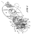
- Each module 2 includes a brake assembly 8 and a brake latch assembly 10.
- FIGURES 1, 2 and 3 show details of the brake assembly 8.
- the brake assembly 8 includes a bracket 12 which is fixed to the machine frame or stand 14 (shown in phantom lines in FIGURES 1 and 2) and to which two opposed brake arms 16 are mounted for pivotal movement about pins 18.
- a brake shoe 20 is pivotally mounted on pins 22 to the brake arms 16 so as to flank the disk 4.
- a coil spring 24 sandwiched between each brake shoe 20 about its respective brake arm 16 biases each brake shoe 20 about its respective pin 22 and toward the inner end of an adjustable screw 23 threaded into each arm 16, such that the brake pads 26 on the shoes 20 remain parallel to each other and to the disk 4. In this manner the pads 26 are prevented from dragging on the disk 4 when the brake is lifted.
- a brake actuating spring 28 is mounted in spring caps 30 carried on spring guides 32 which are secured to the brake arms 16.
- the spring 28 biases the arms 16 outwardly about the pins 18 thereby biasing the brake shoes 20 against the disk 4. This action will occur whenever power is removed from the solenoid 36. In the event of a power failure or an emergency, the brake will automatically sit on the disk. The spring 28 thus supplies the force needed to set the brake.
- Cam pins 34 are mounted on the ends of the arms 16 distal of the brake shoes 20.
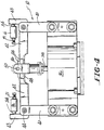
- FIGURES 1 and 4 show details of the brake latching assembly 10.
- the latch 10 includes a solenoid 36 fixed to the machine stand 14 and a solenoid actuated plunger 38 which moves up and down in the solenoid 36.
- Brackets 40 are mounted on opposite sides of the solenoid 36 and latch levers 42 with upturned fingers 43 are pivotally mounted on the brackets 40 via pins 44.
- a clevis 46 is disposed on the plunger 38 and receives overlapping ends 48 of the levers 42.
- a pin 50 spans the clevis 46 and overlies the ends 48 of the levers 42 thereby interconnecting the solenoid plunger 38 and the levers 42.
- the upturned fingers 43 on the levers 42 engage the cam pins 34 on the brake assembly 8.
- the plunger 38 When the solenoid 36 is supplied with electricity, the plunger 38 will be recessed in the solenoid 36, and the clevis 46, levers 42 and cam pins 34 will be in the positions shown in solid lines in FIGURE 4. The cam pins 34 will thus be latched causing compression of the brake actuating spring 28 and lifting the brake shoes 20 off the brake disk 4.
- the elevator controller switches off electrical power to the solenoid 36 allowing the plunger 38 and clevis 46 to rise to the position shown in phantom lines in FIGURE 4.
- a threaded bore 17 is formed to receive an adjustment bolt 19 carrying a lock nut 21.
- the bore 17 opens into a smooth bore 23 in which a pin 25 is slideably disposed.
- the pin 25 has rounded end walls 27 and 29 for providing point contact between the brake arms and levers and may carry a pair of friction rings 31 to snugly hold the pin 25 in place within the bore 23.
- the adjustment bolt 19 allows the pin 25 to move toward and away from finger 43 to thereby allow the positioning of the levers 42 to be modified.
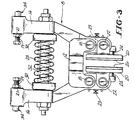
- FIGURE 5 there is shown an alternative embodiment of the invention wherein two actuating springs 27 and 29 are used, one for independently biasing each of the levers 16.
- Each of the springs 27 and 29 seats on a central plate 13 which is fastened to the bracket 12.
- the brake assembly of this invention provides several advantages over prior art caliper disk brakes. Biasing the brake shoes on the brake arms ensures that the brake shoes will not drag on the disk when the brakes are applied or lifted, thereby quieting the brake.
- the use of levers in the latch assembly provides the mechanical advantage sufficient to allow the use of a small latch solenoid having a longer stroke. The longer stroke solenoid allows the use of the stepped core whereby noise may be reduced.
- the use of two actuating springs on the brake assembly assures that spring failure will not completely prevent the brake from operating.
- the modular construction of the assembly enables one unit to be used in lighter duty elevators, and multiple units to be used in heavier duty elevators. It also allows repair and cleaning of the latch assembly components while the brake is set.
Claims (9)
- Ensemble de freinage à étrier (8) comprenant :a) deux patins de frein (20) montés sur deux bras de frein associés (16), lesdits patins de frein (20) ayant des surfaces de freinage opposées (26) ;b) un disque de frein (4) interposé entre lesdits patins de frein (20), ledit disque de frein (4) ayant des surfaces latérales opposées faisant face aux surfaces respectives desdites surfaces de freinage (26) ;c) et un moyen formant ressort (28 ; 27, 29) qui agit sur lesdits bras de frein (16) pour pousser lesdits patins de frein (20) l'un vers l'autre ;caractérisé en ce que ledit ensemble (8) comprend de plus :
d) un moyen de verrouillage (10) comprenant :i) deux leviers montés pivotants (42) destinés à coopérer avec lesdits bras de frein (16) pour maintenir ces derniers à l'encontre de la poussée dudit moyen formant ressort (28 ; 27, 29) ; etii) un moyen de commande de verrouillage à solénoïde (36, 38) comprenant un noyau plongeur (38) coopérant de façon fonctionnelle avec lesdits leviers (42) de manière à maintenir sélectivement ces derniers contre lesdits bras de frein (16), ledit noyau plongeur (38) étant mobile en un mouvement de va-et-vient entre des positions de verrouillage et de déverrouillage pour verrouiller et relâcher sélectivement lesdits bras de frein (16). - Ensemble de freinage (8) selon la revendication 1, dans lequel ledit moyen formant ressort (28 ; 27, 29) pousse indépendamment chacun desdits patins de frein (20) vers l'autre.
- Ensemble de freinage (8) selon la revendication 1 ou 2, dans lequel ledit noyau plongeur (38) fonctionne dans une direction perpendiculaire à la direction de poussée dudit moyen formant ressort (28 ; 27, 29).
- Ensemble de freinage (8) selon la revendication 1, 2 ou 3, dans lequel ledit noyau plongeur (38) est relié aux extrémités adjacentes (48) desdits leviers (42) avec un axe de liaison commun (50).
- Ensemble de freinage (8) selon la revendication 4, dans lequel lesdites extrémités adjacentes (48) desdits leviers (42) se chevauchent.
- Ensemble de freinage (8) selon l'une quelconque des revendications 1 à 5, dans lequel ledit noyau plongeur (38) peut être enlevé d'une bobine de solénoïde associée (36) pour être nettoyé en le détachant desdits leviers (42).
- Ensemble de freinage (8) selon l'une quelconque des revendications 1 à 6, comprenant de plus des moyens de contact pour réaliser un contact de fonctionnement entre lesdits bras de frein (16) et lesdits leviers (42), lesdits moyens de contact comprenant des ergots de contact (34) montés coulissants sur les extrémités desdits bras de frein (16) distantes desdits patins de frein (20), et agencés pour coopérer avec lesdits leviers (42), et des moyens (19, 21) pour approcher et éloigner de manière ajustable lesdits ergots de contact (34) desdits leviers (42) afin de modifier le positionnement desdits leviers (42).
- Ensemble de freinage (8) selon la revendication 7, dans lequel lesdits ergots de contact (34) sont pourvus d'extrémités arrondies coopérant avec lesdits leviers (42) pour former un contact ponctuel entre lesdits bras de frein (16) et lesdits leviers (42).
Applications Claiming Priority (3)
| Application Number | Priority Date | Filing Date | Title |
|---|---|---|---|
| US50862790A | 1990-04-13 | 1990-04-13 | |
| US508627 | 1990-04-13 | ||
| EP19910303295 EP0457436B1 (fr) | 1990-04-13 | 1991-04-15 | Frein à disque pour un ascenseur |
Related Parent Applications (1)
| Application Number | Title | Priority Date | Filing Date |
|---|---|---|---|
| EP91303295.9 Division | 1991-04-15 |
Publications (3)
| Publication Number | Publication Date |
|---|---|
| EP0641950A2 EP0641950A2 (fr) | 1995-03-08 |
| EP0641950A3 EP0641950A3 (fr) | 1995-05-10 |
| EP0641950B1 true EP0641950B1 (fr) | 1997-03-05 |
Family
ID=24023449
Family Applications (2)
| Application Number | Title | Priority Date | Filing Date |
|---|---|---|---|
| EP19910303295 Expired - Lifetime EP0457436B1 (fr) | 1990-04-13 | 1991-04-15 | Frein à disque pour un ascenseur |
| EP94203356A Expired - Lifetime EP0641950B1 (fr) | 1990-04-13 | 1991-04-15 | Frein à disque pour un ascenseur |
Family Applications Before (1)
| Application Number | Title | Priority Date | Filing Date |
|---|---|---|---|
| EP19910303295 Expired - Lifetime EP0457436B1 (fr) | 1990-04-13 | 1991-04-15 | Frein à disque pour un ascenseur |
Country Status (6)
| Country | Link |
|---|---|
| EP (2) | EP0457436B1 (fr) |
| JP (1) | JPH04226291A (fr) |
| AU (1) | AU624039B2 (fr) |
| CA (1) | CA2036363C (fr) |
| DE (2) | DE69125039T2 (fr) |
| ES (2) | ES2078439T3 (fr) |
Families Citing this family (18)
| Publication number | Priority date | Publication date | Assignee | Title |
|---|---|---|---|---|
| DE19719079C1 (de) * | 1997-04-30 | 1998-09-24 | Mannesmann Ag | Notaus-Stoppbremse für Krane |
| FI109788B (fi) * | 1998-06-08 | 2002-10-15 | Kone Corp | Vetopyörähissin pitojarru |
| DE19849749A1 (de) * | 1998-10-28 | 2000-05-04 | Mayr Christian Gmbh & Co Kg | Teilbelag-Federdruckbremse zum Angriff an einer rotierenden Scheibe |
| DE10315985A1 (de) * | 2003-04-07 | 2004-10-28 | Bischoff Autofedern Und Nutzfahrzeugteile Gmbh | Feststellbremse |
| CA2650670A1 (fr) | 2006-04-28 | 2007-11-08 | Electronic Theatre Controls, Inc. | Ensemble, systeme et procede de levage |
| JP4932799B2 (ja) * | 2007-09-13 | 2012-05-16 | 曙ブレーキ工業株式会社 | アジャスタ機能付きパッドホルダ |
| EP2857076B1 (fr) * | 2007-11-08 | 2016-09-21 | Electronic Theatre Controls, Inc. | Système et procédés de gestion de câble de système de levage |
| JP2009208914A (ja) * | 2008-03-05 | 2009-09-17 | Toshiba Elevator Co Ltd | エレベータの縦振動抑制装置 |
| EP2910514B1 (fr) | 2009-11-18 | 2016-10-19 | Electronic Theatre Controls, Inc. | Systèmes et procédés d'assemblage d'ascenseurs |
| JP5361774B2 (ja) * | 2010-03-24 | 2013-12-04 | カヤバ工業株式会社 | キャリパブレーキ装置 |
| US10183850B2 (en) | 2012-12-21 | 2019-01-22 | Electronic Theatre Controls, Inc. | Compact hoist system |
| JP6018906B2 (ja) * | 2012-12-21 | 2016-11-02 | 株式会社日立製作所 | エレベータにおける巻上機用制動器 |
| JP2016034872A (ja) * | 2014-08-04 | 2016-03-17 | 株式会社日立製作所 | エレベータ用巻上機 |
| CN104370237B (zh) * | 2014-11-10 | 2017-01-11 | 巨人通力电梯有限公司 | 一种曳引机制动器 |
| JP6710328B2 (ja) * | 2017-05-24 | 2020-06-17 | 三菱電機株式会社 | エレベータ用巻上機 |
| GB2566497B (en) * | 2017-09-15 | 2020-07-29 | Illinois Tool Works | Braking system for electromagnetic motors |
| CN112268081B (zh) * | 2020-10-26 | 2022-02-08 | 河北翔金超环保科技有限公司 | 一种防偏磨电力液压制动器 |
| CN114132815A (zh) * | 2021-12-31 | 2022-03-04 | 中山天达电梯科技有限公司 | 一种家用电梯轿厢制动装置 |
Family Cites Families (5)
| Publication number | Priority date | Publication date | Assignee | Title |
|---|---|---|---|---|
| GB869070A (en) * | 1956-10-27 | 1961-05-25 | Dunlop Rubber Co | Improvements in braking systems |
| GB1094752A (en) * | 1964-02-22 | 1967-12-13 | J H Carruthers & Company Ltd | Improvements relating to disc brakes |
| FR2334884A1 (fr) * | 1975-10-16 | 1977-07-08 | Pascal Jean Pierre | Pince pour frein a disque |
| GB1581829A (en) * | 1977-05-16 | 1980-12-31 | Wild & Co Ltd M B | Brake apparatus for a winding drum |
| US4696377A (en) * | 1985-09-27 | 1987-09-29 | Ltv Energy Products Company | Brake system for drawworks |
-
1991
- 1991-02-14 CA CA 2036363 patent/CA2036363C/fr not_active Expired - Fee Related
- 1991-03-15 AU AU73598/91A patent/AU624039B2/en not_active Ceased
- 1991-04-15 EP EP19910303295 patent/EP0457436B1/fr not_active Expired - Lifetime
- 1991-04-15 EP EP94203356A patent/EP0641950B1/fr not_active Expired - Lifetime
- 1991-04-15 ES ES91303295T patent/ES2078439T3/es not_active Expired - Lifetime
- 1991-04-15 ES ES94203356T patent/ES2101433T3/es not_active Expired - Lifetime
- 1991-04-15 DE DE1991625039 patent/DE69125039T2/de not_active Expired - Fee Related
- 1991-04-15 DE DE1991611687 patent/DE69111687T2/de not_active Expired - Fee Related
- 1991-04-15 JP JP3109847A patent/JPH04226291A/ja active Pending
Also Published As
| Publication number | Publication date |
|---|---|
| AU7359891A (en) | 1991-10-17 |
| CA2036363A1 (fr) | 1991-10-14 |
| EP0457436B1 (fr) | 1995-08-02 |
| ES2101433T3 (es) | 1997-07-01 |
| EP0641950A3 (fr) | 1995-05-10 |
| DE69111687D1 (de) | 1995-09-07 |
| DE69111687T2 (de) | 1996-05-02 |
| JPH04226291A (ja) | 1992-08-14 |
| EP0641950A2 (fr) | 1995-03-08 |
| DE69125039D1 (de) | 1997-04-10 |
| AU624039B2 (en) | 1992-05-28 |
| ES2078439T3 (es) | 1995-12-16 |
| EP0457436A1 (fr) | 1991-11-21 |
| DE69125039T2 (de) | 1997-10-02 |
| CA2036363C (fr) | 1999-08-24 |
Similar Documents
| Publication | Publication Date | Title |
|---|---|---|
| US5101939A (en) | Disk brake for elevator | |
| EP0641950B1 (fr) | Frein à disque pour un ascenseur | |
| JP4709650B2 (ja) | エレベータ用の遠隔リセット可能なロープ無し非常停止装置 | |
| JP5212971B2 (ja) | ブレーキ装置、エレベータ装置、ブレーキ装置の機能を検出するための方法、および最新化セット | |
| US10562739B2 (en) | Synchronized electronic safety actuator | |
| US8991561B2 (en) | Elevator braking equipment | |
| USRE38835E1 (en) | Remote brake release mechanism for an elevator machine | |
| US20180162694A1 (en) | Electronic safety actuator | |
| US6520299B2 (en) | Disk brake for elevator drive | |
| CN103459290A (zh) | 电梯制动系统 | |
| JP2002532366A (ja) | エレベータかごのロープレスガバナ機構 | |
| EP0388299B1 (fr) | Dispositif d'arrêt pour des escaliers roulants | |
| CN1019566B (zh) | 用于电梯的安全盘式制动器 | |
| US20050087407A1 (en) | Brake for a lift | |
| CN110790109B (zh) | 用于电梯系统的电子安全致动器组件 | |
| JP2010514645A (ja) | エレベーターボックスの領域内にこのエレベーターボックスを保持および制動するためのブレーキ装置を配置したエレベーターボックスを有する昇降システム及びこの形式のエレベーターボックスを保持および制動する方法 | |
| US6425462B1 (en) | Gravity-assisted elevator brake/clutch | |
| US5899304A (en) | Motor brake | |
| US6478124B2 (en) | Brake device for a drive machine of an elevator | |
| JP4513176B2 (ja) | エレベータの制御装置 | |
| EP1481937B1 (fr) | Système de freinage modulaire et adaptable pour une poulie d'ascenseur | |
| US11858781B2 (en) | Frictionless electronic safety actuator | |
| JPWO2002053485A1 (ja) | エレベータの非常ブレーキ装置 | |
| CN216272558U (zh) | 用于电梯制动器的电磁装置、电梯制动器和电梯系统 | |
| WO2023128896A1 (fr) | Frein mécanique fixe pour ascenseurs à moteur linéaire |
Legal Events
| Date | Code | Title | Description |
|---|---|---|---|
| PUAI | Public reference made under article 153(3) epc to a published international application that has entered the european phase |
Free format text: ORIGINAL CODE: 0009012 |
|
| AC | Divisional application: reference to earlier application |
Ref document number: 457436 Country of ref document: EP |
|
| AK | Designated contracting states |
Kind code of ref document: A2 Designated state(s): DE ES FR GB IT |
|
| PUAL | Search report despatched |
Free format text: ORIGINAL CODE: 0009013 |
|
| AK | Designated contracting states |
Kind code of ref document: A3 Designated state(s): DE ES FR GB IT |
|
| 17P | Request for examination filed |
Effective date: 19950710 |
|
| GRAG | Despatch of communication of intention to grant |
Free format text: ORIGINAL CODE: EPIDOS AGRA |
|
| 17Q | First examination report despatched |
Effective date: 19960125 |
|
| GRAH | Despatch of communication of intention to grant a patent |
Free format text: ORIGINAL CODE: EPIDOS IGRA |
|
| GRAH | Despatch of communication of intention to grant a patent |
Free format text: ORIGINAL CODE: EPIDOS IGRA |
|
| ITF | It: translation for a ep patent filed |
Owner name: BARZANO' E ZANARDO ROMA S.P.A. |
|
| GRAA | (expected) grant |
Free format text: ORIGINAL CODE: 0009210 |
|
| AC | Divisional application: reference to earlier application |
Ref document number: 457436 Country of ref document: EP |
|
| AK | Designated contracting states |
Kind code of ref document: B1 Designated state(s): DE ES FR GB IT |
|
| REF | Corresponds to: |
Ref document number: 69125039 Country of ref document: DE Date of ref document: 19970410 |
|
| ET | Fr: translation filed | ||
| REG | Reference to a national code |
Ref country code: ES Ref legal event code: FG2A Ref document number: 2101433 Country of ref document: ES Kind code of ref document: T3 |
|
| PLBE | No opposition filed within time limit |
Free format text: ORIGINAL CODE: 0009261 |
|
| STAA | Information on the status of an ep patent application or granted ep patent |
Free format text: STATUS: NO OPPOSITION FILED WITHIN TIME LIMIT |
|
| 26N | No opposition filed | ||
| PGFP | Annual fee paid to national office [announced via postgrant information from national office to epo] |
Ref country code: ES Payment date: 19980415 Year of fee payment: 8 |
|
| PGFP | Annual fee paid to national office [announced via postgrant information from national office to epo] |
Ref country code: DE Payment date: 19990326 Year of fee payment: 9 |
|
| PG25 | Lapsed in a contracting state [announced via postgrant information from national office to epo] |
Ref country code: ES Free format text: LAPSE BECAUSE OF NON-PAYMENT OF DUE FEES Effective date: 19990416 |
|
| PGFP | Annual fee paid to national office [announced via postgrant information from national office to epo] |
Ref country code: FR Payment date: 20000313 Year of fee payment: 10 |
|
| PGFP | Annual fee paid to national office [announced via postgrant information from national office to epo] |
Ref country code: GB Payment date: 20000321 Year of fee payment: 10 |
|
| PG25 | Lapsed in a contracting state [announced via postgrant information from national office to epo] |
Ref country code: DE Free format text: LAPSE BECAUSE OF NON-PAYMENT OF DUE FEES Effective date: 20010201 |
|
| PG25 | Lapsed in a contracting state [announced via postgrant information from national office to epo] |
Ref country code: GB Free format text: LAPSE BECAUSE OF NON-PAYMENT OF DUE FEES Effective date: 20010415 |
|
| PG25 | Lapsed in a contracting state [announced via postgrant information from national office to epo] |
Ref country code: FR Free format text: THE PATENT HAS BEEN ANNULLED BY A DECISION OF A NATIONAL AUTHORITY Effective date: 20010430 |
|
| REG | Reference to a national code |
Ref country code: ES Ref legal event code: FD2A Effective date: 20010503 |
|
| GBPC | Gb: european patent ceased through non-payment of renewal fee |
Effective date: 20010415 |
|
| REG | Reference to a national code |
Ref country code: FR Ref legal event code: ST |
|
| PG25 | Lapsed in a contracting state [announced via postgrant information from national office to epo] |
Ref country code: IT Free format text: LAPSE BECAUSE OF NON-PAYMENT OF DUE FEES Effective date: 20050415 |