EP0641674A1 - Binding element - Google Patents
Binding element Download PDFInfo
- Publication number
- EP0641674A1 EP0641674A1 EP93202559A EP93202559A EP0641674A1 EP 0641674 A1 EP0641674 A1 EP 0641674A1 EP 93202559 A EP93202559 A EP 93202559A EP 93202559 A EP93202559 A EP 93202559A EP 0641674 A1 EP0641674 A1 EP 0641674A1
- Authority
- EP
- European Patent Office
- Prior art keywords
- file
- binding element
- element according
- heat conducting
- binding
- Prior art date
- Legal status (The legal status is an assumption and is not a legal conclusion. Google has not performed a legal analysis and makes no representation as to the accuracy of the status listed.)
- Granted
Links
Images


Classifications
-
- B—PERFORMING OPERATIONS; TRANSPORTING
- B42—BOOKBINDING; ALBUMS; FILES; SPECIAL PRINTED MATTER
- B42D—BOOKS; BOOK COVERS; LOOSE LEAVES; PRINTED MATTER CHARACTERISED BY IDENTIFICATION OR SECURITY FEATURES; PRINTED MATTER OF SPECIAL FORMAT OR STYLE NOT OTHERWISE PROVIDED FOR; DEVICES FOR USE THEREWITH AND NOT OTHERWISE PROVIDED FOR; MOVABLE-STRIP WRITING OR READING APPARATUS
- B42D3/00—Book covers
- B42D3/02—Book covers made of special materials
-
- B—PERFORMING OPERATIONS; TRANSPORTING
- B42—BOOKBINDING; ALBUMS; FILES; SPECIAL PRINTED MATTER
- B42D—BOOKS; BOOK COVERS; LOOSE LEAVES; PRINTED MATTER CHARACTERISED BY IDENTIFICATION OR SECURITY FEATURES; PRINTED MATTER OF SPECIAL FORMAT OR STYLE NOT OTHERWISE PROVIDED FOR; DEVICES FOR USE THEREWITH AND NOT OTHERWISE PROVIDED FOR; MOVABLE-STRIP WRITING OR READING APPARATUS
- B42D1/00—Books or other bound products
- B42D1/04—Books or other bound products in which the fillings and the spine portions of the covers are secured integrally, e.g. paper-backs ("livres brochès", "Broschüren")
Definitions
- the present invention relates to a binding element, more specifically to a binding element of the type of which the inside of the back is provided with an amount of glue which melts under the influence of heat.
- Binding elements of the above-mentioned type are widely known.
- the sheets are placed in contact with the glue in the binding element. Consecutively, the whole is placed vertically, the back facing down, on a heating element, so that the glue melts and the sheets intrude in the glue layer. After the binding element has been taken off the heating element, the glue hardens, with as a result that the sheets are retained in the binding element by means of the glue.
- the above-mentioned element can consist of a metal U-shaped profile.
- An example thereof is disclosed in GB 2.197.156.
- the use of such U-shaped profile also offers the advantage that, when laying the bound bundle open, respectively turning the pages thereof, the glue connections between the sheets, as well as the glue connections between the sheets themselves, is burdened little or not at all, thus avoiding that the sheets come loose.
- the U-shaped profile is located at the inside of the file.
- the binding element therefore has the disadvantage that it is very user-unfriendly, as it is very difficult to slide all sheets into the U-shaped profile, especially with thick bundles. Indeed, the outer sheets end up on the edge of the relatively thick metal profile.
- the invention therefore aims at a binding element whereby the above-mentioned disadvantage is excluded, and more specifically at a binding element whereby said heat conducting element, whether this has a U-shaped section or not, does not trouble when inserting a bundle of loose documents in this binding element.
- the invention relates to a binding element, consisting of an actual file which is made of one or more parts, the back of which contains an element in a hard heat conducting material, and whereby the back is provided at its inside with an amount of glue which melts under the influence of heat, characterized in that the file, at least partially, is adjacent to the inside of said element.
- a binding element consisting of an actual file which is made of one or more parts, the back of which contains an element in a hard heat conducting material, and whereby the back is provided at its inside with an amount of glue which melts under the influence of heat, characterized in that the file, at least partially, is adjacent to the inside of said element.
- loose sheets which are inserted in the file can slide into the right position in an unhindered way.
- the sheets to be bound are lead as far as next to the upright walls of the U-shaped element.
- the portions of the file adjacent to the inside of the heat conducting element are preferably glued to the latter, for instance with a once-only activatable glue. This is especially important when a continuous inner cover is applied against the heat conducting element, as such glued connection ensures that the inner cover is always in perfect contact with the heat conducting element, and thus the glue for binding the documents is also in perfect contact with the heat conducting element.
- the invention relates to a binding element 1, consisting of, on the one hand, an actual file 2 which is composed of one or more parts, and provided at the inside of its back 3 with an amount of glue 4 which melts under influence of heat, and on the other hand, an element 5 in a hard and heat conducting material, applied at the back 3.
- the file 2 is formed of one continuous sheet of paper, synthetic material or the like which is attached to the inside 6 of the element 5.
- the sheet forms a front sheet 7, a back portion 8 and rear sheet 9.
- Said glue 4 consists of a strip of hardened adhesive which is applied to the inside of the back portion 8.
- the element 5 consists of a U-shaped profile with rectangular section, formed of a back wall 10 and two side walls 11 and 12.
- the file 2 fits tightly against the inside 6 of the element 5, or at least fits tightly against the back wall 10 of the element 5, so that the heat transfer W of the element 5 to the glue 4 is optimal and for example not hindered by air inclusions or the like.
- the portions of the file 2 adjacent to the inside 6 are therefore, with their entire surface or not, adhered to the latter, as is represented in the detail view of figure 2.
- the glue is of such a kind that it will not come loose during the heating when binding documents.
- openings 14 can be applied in the portions of the file 2 adjacent to the inside 6, which allow a bulge 15 of the glue, thus causing that a better adhesion is obtained, especially around the edges 16 of the openings 14.
- Figure 3 represents the use of the binding element 1 of figure 1.
- the binding element 1 is placed on a heating element 18, together with the documents 17 to be bound.
- the glue 4 melts and the documents 17 intrude at their bottom edges in the glue 4.
- the documents 17 are secured in the binding element 1.
- FIG 4 a variant is represented whereby the front sheet 7 and the rear sheet 9 of the file 2 consist of separate sheets which are both attached to the inside 6 of the respective side walls 11 and 12, preferably by means of glueing.
- the sheets 7 and 9 can hereby also be provided with openings 14 as described above.
- the glue 4 can be directly applied to the element 5.
- the element 5 can be provided with a covering 21, for example a material with an elegant aspect, for example printed paper.
- the covering 21 is preferably folded over the edges of the element 5, whereby the folded parts 22 and 23 are located between the side walls 11 and 12 and the front sheet 7 and the rear sheet 9.
- figure 5 an embodiment is represented whereby the front sheet 7, the back portion 8 and the rear sheet 9 are made of one sheet
- figure 6 represents an embodiment whereby use is made of a separate front sheet 7, rear sheet 9 and a connection strip 24 which is adjacent to the element 5, respectively to the folded parts 22 and 23.
- the sheets 7 and 9 are hereby only attached to the connection strip 24, preferably by means of glueing.
- the build-up of figure 6 is of course also possible without the covering 21 being present.
- connection strip 24 is especially suitable in case that is opted for a front sheet 7 and/or rear sheet 9 of a relatively stiff material, for example transparent synthetic foil.
- the connection strip 24 can than be made of a more supple material than the front sheet 7 and the rear sheet 9, so that the folding open of the binding element 1, despite the use of a front sheet 7 and/or rear sheet 9 of a relatively stiff material, is not hindered.
- the front sheet 7 and rear sheet 9 both consist of a cardboard plate.
- a connection strip 24 is applied, for example made of paper, which is adjacent to the inside of the element 5, and is preferably glued to the latter.
- the whole is covered with an outer cover 25, preferably with an elegant aspect, for example of printed or coloured paper, with or without relief.
- the outer covering 25 can be folded at all edges of the binding element 1.
- the front sheet 7 and the rear sheet 9 are attached at a certain distance D from the element 5, so that folding zones 26 are formed, which allows the binding element 1 to be folded open as represented in figure 8. These folding zones 26 are also indicated in figure 6.
- openings 27 can be applied in the material of the file 2 that is adjacent to the inside 6 of the element 5, which allow the direct heat transfer from the heat conducting element 5 to the glue 4.
- these openings 27 exist in a continuous perforation over the entire back. According to a variant, which is not represented, one long continuous excision can be provided.
- connection strip 24 forms part of a continuous inner covering 28.
- FIGs 10 and 11 represent two further variants whereby the glue 4 is in direct contact with the element 5.
- Figure 12 represents a variant whereby the heat conducting element 5 consists of a flat strip.
- the file 2 is hereby adjacent to the inside 6 of the element 5, with which is meant the side directed towards the inside of the binding element 1, it is excluded that documents 17 which are inserted in the binding element 1 end up next to the element 5. It is clear that also in this case the file 2 can be assembled in different forms.
- the element 5 is preferably made of metal and in the most preferred embodiment of steel. It is to be understood that by the above-mentioned expression "hard material” is meant that the element 5 is made of a material which is little or not bendable and is certainly less bendable than paper or synthetic foil.
Abstract
Description
- The present invention relates to a binding element, more specifically to a binding element of the type of which the inside of the back is provided with an amount of glue which melts under the influence of heat.
- Binding elements of the above-mentioned type are widely known. In order to bind a bundle of sheets or documents by means of such binding element, the sheets are placed in contact with the glue in the binding element. Consecutively, the whole is placed vertically, the back facing down, on a heating element, so that the glue melts and the sheets intrude in the glue layer. After the binding element has been taken off the heating element, the glue hardens, with as a result that the sheets are retained in the binding element by means of the glue.
- In order to obtain that the heat of the heating element is fed to the glue in an efficient way, more specifically is spread very equally, it is also known to apply an element of a heat conducting material, such as metal, in the back.
- It is also known that the above-mentioned element can consist of a metal U-shaped profile. An example thereof is disclosed in GB 2.197.156. The use of such U-shaped profile also offers the advantage that, when laying the bound bundle open, respectively turning the pages thereof, the glue connections between the sheets, as well as the glue connections between the sheets themselves, is burdened little or not at all, thus avoiding that the sheets come loose.
- According to GB 2.197.156, the U-shaped profile is located at the inside of the file. The binding element therefore has the disadvantage that it is very user-unfriendly, as it is very difficult to slide all sheets into the U-shaped profile, especially with thick bundles. Indeed, the outer sheets end up on the edge of the relatively thick metal profile.
- The invention therefore aims at a binding element whereby the above-mentioned disadvantage is excluded, and more specifically at a binding element whereby said heat conducting element, whether this has a U-shaped section or not, does not trouble when inserting a bundle of loose documents in this binding element.
- To this end, the invention relates to a binding element, consisting of an actual file which is made of one or more parts, the back of which contains an element in a hard heat conducting material, and whereby the back is provided at its inside with an amount of glue which melts under the influence of heat, characterized in that the file, at least partially, is adjacent to the inside of said element. As the file is at least partially adjacent to the inside of the heat conducting element, loose sheets which are inserted in the file can slide into the right position in an unhindered way.
- Indeed, in case a U-shaped heat conducting element is used, the sheets to be bound are lead as far as next to the upright walls of the U-shaped element.
- In case a flat heat conducting element is used, it is excluded that the outer sheets end up next to the heat conducting element.
- The portions of the file adjacent to the inside of the heat conducting element are preferably glued to the latter, for instance with a once-only activatable glue. This is especially important when a continuous inner cover is applied against the heat conducting element, as such glued connection ensures that the inner cover is always in perfect contact with the heat conducting element, and thus the glue for binding the documents is also in perfect contact with the heat conducting element.
- In order to better illustrate the characteristics according to the invention, some preferred embodiments are described hereafter, as examples with no limiting character whatsoever, reference being made to the accompanying drawings, in which:
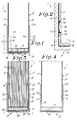
- figure 1 represents a cross-section of a binding element according to the invention;
- figure 2 represents the part marked with F2 in figure 1, on an enlarged scale;
- figure 3 represents the binding element of figure 1 during use;
- figures 4 to 7 represent four variants of binding elements according to the invention;
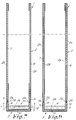
- figure 8 represents a part of the binding element of figure 7 in opened position;
- figures 9 to 12 represents four more variants of binding elements according to the invention.
- As represented in figure 1, the invention relates to a
binding element 1, consisting of, on the one hand, anactual file 2 which is composed of one or more parts, and provided at the inside of itsback 3 with an amount ofglue 4 which melts under influence of heat, and on the other hand, anelement 5 in a hard and heat conducting material, applied at theback 3. - The particularity of the invention exists in that the
file 2, at least partially, thus with a number of components parts thereof, is adjacent to theinside 6 of saidelement 5. - This characteristic can be realized in different ways. To this end, in the embodiment of figure 1, the
file 2 is formed of one continuous sheet of paper, synthetic material or the like which is attached to theinside 6 of theelement 5. Thus the sheet forms afront sheet 7, aback portion 8 andrear sheet 9. Saidglue 4 consists of a strip of hardened adhesive which is applied to the inside of theback portion 8. - According to figure 1, the
element 5 consists of a U-shaped profile with rectangular section, formed of aback wall 10 and twoside walls - Preferably, the
file 2 fits tightly against theinside 6 of theelement 5, or at least fits tightly against theback wall 10 of theelement 5, so that the heat transfer W of theelement 5 to theglue 4 is optimal and for example not hindered by air inclusions or the like. Preferably, the portions of thefile 2 adjacent to theinside 6 are therefore, with their entire surface or not, adhered to the latter, as is represented in the detail view of figure 2. To this end, use can be made of a thin layer ofglue 13. The glue is of such a kind that it will not come loose during the heating when binding documents. To this end, use can be made of a thermo-activatable glue, the melting temperature of which is considerably higher than the binding temperature, a once-only thermo-activatable glue or a non-thermic glue. - As is represented further in figures 1 and 2,
openings 14 can be applied in the portions of thefile 2 adjacent to theinside 6, which allow abulge 15 of the glue, thus causing that a better adhesion is obtained, especially around theedges 16 of theopenings 14. - It is to be noted that instead of a connection by means of the
glue 13, according to an embodiment not represented in the figures, the portions of thefile 2 adjacent to theinside 6 of theelement 5 can also be clenched in the latter. - Figure 3 represents the use of the
binding element 1 of figure 1. During the binding, thebinding element 1 is placed on a heating element 18, together with thedocuments 17 to be bound. Hereby, theglue 4 melts and thedocuments 17 intrude at their bottom edges in theglue 4. After the whole has hardened again, thedocuments 17 are secured in thebinding element 1. - It is clear that, during the insertion in the
binding element 1, thedocuments 17 can easily glide according to arrows A between theside walls U-shaped element 5, respectively can be tapped between them, thanks to the fact that thefile 2 is adjacent to the inside of theelement 5. Indeed, thedocuments 17 cannot end up on the relativelywide edges element 5. - In figure 4 a variant is represented whereby the
front sheet 7 and therear sheet 9 of thefile 2 consist of separate sheets which are both attached to theinside 6 of therespective side walls sheets openings 14 as described above. - According to the embodiment of figure 4, the
glue 4 can be directly applied to theelement 5. - As represented in figures 5 and 6, the
element 5 can be provided with a covering 21, for example a material with an elegant aspect, for example printed paper. Thecovering 21 is preferably folded over the edges of theelement 5, whereby the foldedparts side walls front sheet 7 and therear sheet 9. - It is to be noted that in figure 5 an embodiment is represented whereby the
front sheet 7, theback portion 8 and therear sheet 9 are made of one sheet, while figure 6 represents an embodiment whereby use is made of aseparate front sheet 7,rear sheet 9 and aconnection strip 24 which is adjacent to theelement 5, respectively to the foldedparts sheets connection strip 24, preferably by means of glueing. The build-up of figure 6 is of course also possible without the covering 21 being present. - The build-up with the
connection strip 24 is especially suitable in case that is opted for afront sheet 7 and/orrear sheet 9 of a relatively stiff material, for example transparent synthetic foil. Theconnection strip 24 can than be made of a more supple material than thefront sheet 7 and therear sheet 9, so that the folding open of thebinding element 1, despite the use of afront sheet 7 and/orrear sheet 9 of a relatively stiff material, is not hindered. - According to the embodiment in figure 7 the
front sheet 7 andrear sheet 9 both consist of a cardboard plate. At the inside aconnection strip 24 is applied, for example made of paper, which is adjacent to the inside of theelement 5, and is preferably glued to the latter. - The whole is covered with an
outer cover 25, preferably with an elegant aspect, for example of printed or coloured paper, with or without relief. Theouter covering 25 can be folded at all edges of thebinding element 1. - As is further represented in figure 7, the
front sheet 7 and therear sheet 9 are attached at a certain distance D from theelement 5, so thatfolding zones 26 are formed, which allows thebinding element 1 to be folded open as represented in figure 8. Thesefolding zones 26 are also indicated in figure 6. - As represented in figure 8,
openings 27 can be applied in the material of thefile 2 that is adjacent to theinside 6 of theelement 5, which allow the direct heat transfer from theheat conducting element 5 to theglue 4. Preferably, theseopenings 27 exist in a continuous perforation over the entire back. According to a variant, which is not represented, one long continuous excision can be provided. - In figure 9, a variant of figure 7 is represented, whereby the
connection strip 24 forms part of a continuousinner covering 28. - Figures 10 and 11 represent two further variants whereby the
glue 4 is in direct contact with theelement 5. - Figure 12 represents a variant whereby the
heat conducting element 5 consists of a flat strip. As thefile 2 is hereby adjacent to theinside 6 of theelement 5, with which is meant the side directed towards the inside of thebinding element 1, it is excluded thatdocuments 17 which are inserted in thebinding element 1 end up next to theelement 5. It is clear that also in this case thefile 2 can be assembled in different forms. The example of figure 12, in which theactual file 2 consists of afront sheet 7, aback portion 8 and arear sheet 9 which are made of one single sheet of paper, synthetic material or the like, and acovering strip 19 which is applied to the outside of theelement 5, is therefore in no way limitative. - In the above-described embodiments, the
element 5 is preferably made of metal and in the most preferred embodiment of steel. It is to be understood that by the above-mentioned expression "hard material" is meant that theelement 5 is made of a material which is little or not bendable and is certainly less bendable than paper or synthetic foil. - It is clear that the different characteristics of different embodiments can be mutually combined.
- The present invention is in no way limited to the embodiments described above and represented in the drawings, but such binding element can be realized in different forms and dimensions without leaving the scope of the invention as defined in the enclosed claims.
Claims (16)
- Binding element, consisting of an actual file (2) which is composed of one or more parts, the back (3) of which contains an element (5) in a hard heat conducting material, and whereby the back (3) is provided at its inside with an amount of glue (4) which melts under the influence of heat, characterized in that the file (2), at least partially, is adjacent to the inside (6) of said element (5).
- Binding element according to claim 1, characterized in that the portions of the file (2) which are adjacent to the inside (6) of said element (5) fit tightly against the latter.
- Binding element according to claim 2, characterized in that the portions of the file (2) which are adjacent to the inside (6) of said element (5) are at least partially glued to the latter.
- Binding element according to claim 2 or 3, characterized in that the portions of the file (2) which are adjacent to the inside (6) of said element (5) are clenched in the latter.
- Binding element according to claim 3, characterized in that the portions of the file (2) which are adjacent to the inside (6) of said element (5) are provided with openings (14) improving the adhesion with glue.
- Binding element according to any one of the preceding claims, characterized in that the heat conducting element (5) consists of a profile with U-shaped section.
- Binding element according to any one of claims 1 to 5, characterized in that the heat conducting element (5) consists of a flat strip.
- Binding element according to any one of the preceding claims, characterized in that the file (2) is provided with a front sheet (7), a back portion (8) and a rear sheet (9), which are manufactured of one single sheet, which is attached to the inside (6) of the element (5).
- Binding element according to claim 6, characterized in that the file (2) contains a separate front sheet (7) and rear sheet (9), which are attached to the insides (6) of the side walls (11, 12) of the legs of the U-shaped profile.
- Binding element according to any one of claims 6 or 9, characterized in that the outside of the U-shaped heat conducting element (5) is provided with a covering (21).
- Binding element according to any one of claims 1 to 7, characterized in that the file (2) is composed at least of a separate front sheet (7), extending upto a distance (D) of the heat conducting element (5), a separate rear sheet (9), also extending upto a distance (D) from the heat conducting element (5), and at least one connection strip (24), forming the connection between the front sheet (7), the heat conducting element (5) and the rear sheet (9).
- Binding element according to claim 11, characterized in that the front sheet (7) and the rear sheet (9) are made of a stiff material, and that the connection strip (24) provides in folding zones (26).
- Binding element according to claim 12, characterized in that the front sheet (7) and the rear sheet (9) are made of cardboard.
- Binding element according to any one of the preceding claims, characterized in that the file (2) is provided with a continuous outer covering (25), extending around the whole.
- Binding element according to claim 11, characterized in that the front sheet (7) and the rear sheet (9) are made of transparent synthetic foil and that the connection strip (24) is made of a more supple synthetic foil.
- Binding element according to any one of the preceding claims, characterized in that the portions of the file (2) which are adjacent to the heat conducting element (5) and on which the glue (4), which melts under the influence of heat, is applied, are provided with openings (27) which allow a direct heat transfer from the heat conducting element (5) to the concerned glue (4).
Priority Applications (14)
| Application Number | Priority Date | Filing Date | Title |
|---|---|---|---|
| EP93202559A EP0641674B1 (en) | 1993-09-01 | 1993-09-01 | Binding element |
| ES93202559T ES2118182T3 (en) | 1993-09-01 | 1993-09-01 | FIXING ELEMENT. |
| AT93202559T ATE165563T1 (en) | 1993-09-01 | 1993-09-01 | BINDING ELEMENT |
| DE69318296T DE69318296T2 (en) | 1993-09-01 | 1993-09-01 | Binding element |
| DK93202559T DK0641674T3 (en) | 1993-09-01 | 1993-09-01 | Tie element |
| AU48863/93A AU671148B2 (en) | 1992-10-09 | 1993-10-06 | Binding element |
| MYPI93002039A MY109959A (en) | 1992-10-09 | 1993-10-07 | Binding element |
| CA002108082A CA2108082C (en) | 1992-10-09 | 1993-10-08 | Binder |
| US08/133,308 US5425554A (en) | 1992-10-09 | 1993-10-08 | Binding element |
| BR9304197A BR9304197A (en) | 1992-10-09 | 1993-10-08 | Binding element |
| MX9306263A MX9306263A (en) | 1992-10-09 | 1993-10-08 | BINDING ELEMENT. |
| KR1019930020784A KR100266462B1 (en) | 1992-10-09 | 1993-10-08 | Binding element |
| JP5253396A JP2908197B2 (en) | 1992-10-09 | 1993-10-08 | Binding element |
| CN93114430A CN1042509C (en) | 1992-10-09 | 1993-10-09 | Binding element |
Applications Claiming Priority (1)
| Application Number | Priority Date | Filing Date | Title |
|---|---|---|---|
| EP93202559A EP0641674B1 (en) | 1993-09-01 | 1993-09-01 | Binding element |
Publications (2)
| Publication Number | Publication Date |
|---|---|
| EP0641674A1 true EP0641674A1 (en) | 1995-03-08 |
| EP0641674B1 EP0641674B1 (en) | 1998-04-29 |
Family
ID=8214073
Family Applications (1)
| Application Number | Title | Priority Date | Filing Date |
|---|---|---|---|
| EP93202559A Expired - Lifetime EP0641674B1 (en) | 1992-10-09 | 1993-09-01 | Binding element |
Country Status (5)
| Country | Link |
|---|---|
| EP (1) | EP0641674B1 (en) |
| AT (1) | ATE165563T1 (en) |
| DE (1) | DE69318296T2 (en) |
| DK (1) | DK0641674T3 (en) |
| ES (1) | ES2118182T3 (en) |
Cited By (5)
| Publication number | Priority date | Publication date | Assignee | Title |
|---|---|---|---|---|
| DE19909186A1 (en) * | 1999-03-03 | 2000-09-28 | Copy Lein Gmbh | Modified book cover |
| DE10108525A1 (en) * | 2001-02-22 | 2002-09-05 | Heidelberger Druckmasch Ag | Binding element and binding device for digital printing |
| BE1015678A3 (en) * | 2003-09-09 | 2005-07-05 | Uniband Cyprus Ltd | Improved binding element. |
| BE1017215A3 (en) | 2006-07-11 | 2008-05-06 | Unibind Ltd | Production method for thermal binding element, involves pressing hot=melt adhesive applied to binding element to uniform thickness |
| US7500813B2 (en) | 2004-05-21 | 2009-03-10 | Esselte Business Bvba | Punching and binding system and elements thereof |
Families Citing this family (1)
| Publication number | Priority date | Publication date | Assignee | Title |
|---|---|---|---|---|
| BE1020225A3 (en) | 2011-10-07 | 2013-06-04 | Unibind Ltd | A METHOD FOR BINDING LEAVES AND A BINDING ELEMENT AND BINDING DEVICE APPLIED THEREOF. |
Citations (4)
| Publication number | Priority date | Publication date | Assignee | Title |
|---|---|---|---|---|
| GB1029687A (en) * | 1963-11-21 | 1966-05-18 | Print & Plastics Proprietary L | Improvements in bookbinding |
| GB2197256A (en) * | 1986-11-13 | 1988-05-18 | Unibind Ltd | Element for binding sheets |
| GB2218043A (en) * | 1988-05-06 | 1989-11-08 | Executive Products Limited | Thermal binding |
| GB2223450A (en) * | 1985-09-25 | 1990-04-11 | Easibind Ltd | Book cover |
-
1993
- 1993-09-01 ES ES93202559T patent/ES2118182T3/en not_active Expired - Lifetime
- 1993-09-01 AT AT93202559T patent/ATE165563T1/en active
- 1993-09-01 DE DE69318296T patent/DE69318296T2/en not_active Expired - Lifetime
- 1993-09-01 DK DK93202559T patent/DK0641674T3/en active
- 1993-09-01 EP EP93202559A patent/EP0641674B1/en not_active Expired - Lifetime
Patent Citations (4)
| Publication number | Priority date | Publication date | Assignee | Title |
|---|---|---|---|---|
| GB1029687A (en) * | 1963-11-21 | 1966-05-18 | Print & Plastics Proprietary L | Improvements in bookbinding |
| GB2223450A (en) * | 1985-09-25 | 1990-04-11 | Easibind Ltd | Book cover |
| GB2197256A (en) * | 1986-11-13 | 1988-05-18 | Unibind Ltd | Element for binding sheets |
| GB2218043A (en) * | 1988-05-06 | 1989-11-08 | Executive Products Limited | Thermal binding |
Cited By (12)
| Publication number | Priority date | Publication date | Assignee | Title |
|---|---|---|---|---|
| DE19909186A1 (en) * | 1999-03-03 | 2000-09-28 | Copy Lein Gmbh | Modified book cover |
| DE19909186C2 (en) * | 1999-03-03 | 2001-04-12 | Copy Lein Gmbh | Modified book cover |
| EP1187726B1 (en) * | 1999-03-03 | 2003-06-11 | Copy - Lein GmbH | Modified book cover |
| US6581970B1 (en) | 1999-03-03 | 2003-06-24 | Copy-Lein Gmbh | Modified book binding |
| DE10108525A1 (en) * | 2001-02-22 | 2002-09-05 | Heidelberger Druckmasch Ag | Binding element and binding device for digital printing |
| BE1015678A3 (en) * | 2003-09-09 | 2005-07-05 | Uniband Cyprus Ltd | Improved binding element. |
| US7500813B2 (en) | 2004-05-21 | 2009-03-10 | Esselte Business Bvba | Punching and binding system and elements thereof |
| US7503740B2 (en) | 2004-05-21 | 2009-03-17 | Esselte | Punching and binding system and elements thereof |
| US7628103B2 (en) | 2004-05-21 | 2009-12-08 | Esselte | Punching and binding systems and elements thereof |
| US7665943B2 (en) | 2004-05-21 | 2010-02-23 | Esselte Business Bvba | Punching and binding system and elements thereof |
| US7748941B2 (en) | 2004-05-21 | 2010-07-06 | Esselte Business Bvba | Punching and binding system and elements thereof |
| BE1017215A3 (en) | 2006-07-11 | 2008-05-06 | Unibind Ltd | Production method for thermal binding element, involves pressing hot=melt adhesive applied to binding element to uniform thickness |
Also Published As
| Publication number | Publication date |
|---|---|
| ATE165563T1 (en) | 1998-05-15 |
| DE69318296D1 (en) | 1998-06-04 |
| ES2118182T3 (en) | 1998-09-16 |
| DK0641674T3 (en) | 1999-02-15 |
| DE69318296T2 (en) | 1998-12-17 |
| EP0641674B1 (en) | 1998-04-29 |
Similar Documents
| Publication | Publication Date | Title |
|---|---|---|
| CA2108082C (en) | Binder | |
| EP0363345B1 (en) | Universal binding element for binding loose documents in a file | |
| EP1213155B1 (en) | End leaf and binding element containing such an end leaf | |
| RU99126866A (en) | METHOD FOR MANUFACTURING A BOOKLET, A BOOKLET MANUFACTURED ACCORDING TO THE WAY, AND A BOOKLET | |
| EP2152523A1 (en) | Media binder systems with datum stops for registering physical media sheets | |
| GB2028718A (en) | Book covers | |
| US6669392B2 (en) | Device for binding sheets and bound sheets | |
| EP0641674B1 (en) | Binding element | |
| US5873601A (en) | Binding element for sheets | |
| EP0347404A1 (en) | Binding element for binding loose sheets in a file | |
| US4537544A (en) | Method of forming a folder for reports or statements of account and cover to effect the method | |
| GB2184981A (en) | A book and method of producing same | |
| WO1990015722A1 (en) | Binding element with removable flyleaf | |
| KR20050026366A (en) | Improved binding element | |
| RU2101186C1 (en) | Interlacing member | |
| EP0087976B1 (en) | Folders for documents | |
| CA1221599A (en) | Folders for documents | |
| AU2002100656A4 (en) | Document binding means and method | |
| BE1006325A3 (en) | Binder | |
| US20040234329A1 (en) | Loose leaf binder | |
| AU6538999A (en) | Document binding means and method | |
| ITRE980037U1 (en) | MEANS TO BIND FILE TO A DEVICE-COLLECTOR OF FILE. | |
| CA2357557A1 (en) | Report cover |
Legal Events
| Date | Code | Title | Description |
|---|---|---|---|
| PUAI | Public reference made under article 153(3) epc to a published international application that has entered the european phase |
Free format text: ORIGINAL CODE: 0009012 |
|
| AK | Designated contracting states |
Kind code of ref document: A1 Designated state(s): AT BE CH DE DK ES FR GB GR IE IT LI LU MC NL PT SE |
|
| 17P | Request for examination filed |
Effective date: 19950621 |
|
| 111L | Licence recorded |
Free format text: 950308 0100 ERGONBEDRIJVEN |
|
| RAP1 | Party data changed (applicant data changed or rights of an application transferred) |
Owner name: UNIBIND (CYPRUS) LIMITED |
|
| 17Q | First examination report despatched |
Effective date: 19960503 |
|
| GRAG | Despatch of communication of intention to grant |
Free format text: ORIGINAL CODE: EPIDOS AGRA |
|
| GRAG | Despatch of communication of intention to grant |
Free format text: ORIGINAL CODE: EPIDOS AGRA |
|
| GRAH | Despatch of communication of intention to grant a patent |
Free format text: ORIGINAL CODE: EPIDOS IGRA |
|
| GRAH | Despatch of communication of intention to grant a patent |
Free format text: ORIGINAL CODE: EPIDOS IGRA |
|
| GRAA | (expected) grant |
Free format text: ORIGINAL CODE: 0009210 |
|
| AK | Designated contracting states |
Kind code of ref document: B1 Designated state(s): AT BE CH DE DK ES FR GB GR IE IT LI LU MC NL PT SE |
|
| REF | Corresponds to: |
Ref document number: 165563 Country of ref document: AT Date of ref document: 19980515 Kind code of ref document: T |
|
| REG | Reference to a national code |
Ref country code: CH Ref legal event code: EP |
|
| REF | Corresponds to: |
Ref document number: 69318296 Country of ref document: DE Date of ref document: 19980604 |
|
| REG | Reference to a national code |
Ref country code: CH Ref legal event code: NV Representative=s name: DIPL.-ING. ETH H. R. WERFFELI PATENTANWALT |
|
| ITF | It: translation for a ep patent filed |
Owner name: NOTARBARTOLO & GERVASI S.P.A. |
|
| REG | Reference to a national code |
Ref country code: IE Ref legal event code: FG4D Free format text: 80071 |
|
| ET | Fr: translation filed | ||
| REG | Reference to a national code |
Ref country code: ES Ref legal event code: FG2A Ref document number: 2118182 Country of ref document: ES Kind code of ref document: T3 |
|
| REG | Reference to a national code |
Ref country code: PT Ref legal event code: SC4A Free format text: AVAILABILITY OF NATIONAL TRANSLATION Effective date: 19980716 |
|
| REG | Reference to a national code |
Ref country code: DK Ref legal event code: T3 |
|
| PLBE | No opposition filed within time limit |
Free format text: ORIGINAL CODE: 0009261 |
|
| STAA | Information on the status of an ep patent application or granted ep patent |
Free format text: STATUS: NO OPPOSITION FILED WITHIN TIME LIMIT |
|
| PGFP | Annual fee paid to national office [announced via postgrant information from national office to epo] |
Ref country code: ES Payment date: 19990323 Year of fee payment: 6 |
|
| 26N | No opposition filed | ||
| PG25 | Lapsed in a contracting state [announced via postgrant information from national office to epo] |
Ref country code: ES Free format text: LAPSE BECAUSE OF NON-PAYMENT OF DUE FEES Effective date: 19990902 |
|
| REG | Reference to a national code |
Ref country code: GB Ref legal event code: IF02 |
|
| REG | Reference to a national code |
Ref country code: ES Ref legal event code: FD2A Effective date: 20001013 |
|
| PG25 | Lapsed in a contracting state [announced via postgrant information from national office to epo] |
Ref country code: IT Free format text: LAPSE BECAUSE OF NON-PAYMENT OF DUE FEES Effective date: 20050901 |
|
| REG | Reference to a national code |
Ref country code: SE Ref legal event code: RPOT |
|
| NLR4 | Nl: receipt of corrected translation in the netherlands language at the initiative of the proprietor of the patent | ||
| PGFP | Annual fee paid to national office [announced via postgrant information from national office to epo] |
Ref country code: DE Payment date: 20101113 Year of fee payment: 18 |
|
| PGRI | Patent reinstated in contracting state [announced from national office to epo] |
Ref country code: IT Effective date: 20110616 |
|
| PGFP | Annual fee paid to national office [announced via postgrant information from national office to epo] |
Ref country code: LU Payment date: 20110819 Year of fee payment: 19 |
|
| PGFP | Annual fee paid to national office [announced via postgrant information from national office to epo] |
Ref country code: IE Payment date: 20110822 Year of fee payment: 19 Ref country code: MC Payment date: 20110825 Year of fee payment: 19 Ref country code: CH Payment date: 20110824 Year of fee payment: 19 Ref country code: DK Payment date: 20110824 Year of fee payment: 19 |
|
| PGFP | Annual fee paid to national office [announced via postgrant information from national office to epo] |
Ref country code: FR Payment date: 20110901 Year of fee payment: 19 Ref country code: AT Payment date: 20110927 Year of fee payment: 19 Ref country code: GB Payment date: 20110825 Year of fee payment: 19 Ref country code: SE Payment date: 20110824 Year of fee payment: 19 Ref country code: GR Payment date: 20110923 Year of fee payment: 19 Ref country code: PT Payment date: 20110819 Year of fee payment: 19 |
|
| PGFP | Annual fee paid to national office [announced via postgrant information from national office to epo] |
Ref country code: BE Payment date: 20110819 Year of fee payment: 19 Ref country code: IT Payment date: 20110906 Year of fee payment: 19 |
|
| PGFP | Annual fee paid to national office [announced via postgrant information from national office to epo] |
Ref country code: NL Payment date: 20111004 Year of fee payment: 19 |
|
| REG | Reference to a national code |
Ref country code: PT Ref legal event code: MM4A Free format text: LAPSE DUE TO NON-PAYMENT OF FEES Effective date: 20130301 |
|
| BERE | Be: lapsed |
Owner name: *UNIBIND (CYPRUS) LTD Effective date: 20120930 |
|
| REG | Reference to a national code |
Ref country code: NL Ref legal event code: V1 Effective date: 20130401 |
|
| PG25 | Lapsed in a contracting state [announced via postgrant information from national office to epo] |
Ref country code: MC Free format text: LAPSE BECAUSE OF NON-PAYMENT OF DUE FEES Effective date: 20120930 Ref country code: SE Free format text: LAPSE BECAUSE OF NON-PAYMENT OF DUE FEES Effective date: 20120902 |
|
| REG | Reference to a national code |
Ref country code: CH Ref legal event code: PL Ref country code: SE Ref legal event code: EUG |
|
| REG | Reference to a national code |
Ref country code: AT Ref legal event code: MM01 Ref document number: 165563 Country of ref document: AT Kind code of ref document: T Effective date: 20120901 |
|
| REG | Reference to a national code |
Ref country code: GR Ref legal event code: ML Ref document number: 980401688 Country of ref document: GR Effective date: 20130404 |
|
| GBPC | Gb: european patent ceased through non-payment of renewal fee |
Effective date: 20120901 |
|
| PG25 | Lapsed in a contracting state [announced via postgrant information from national office to epo] |
Ref country code: PT Free format text: LAPSE BECAUSE OF NON-PAYMENT OF DUE FEES Effective date: 20130301 |
|
| REG | Reference to a national code |
Ref country code: DK Ref legal event code: EBP |
|
| REG | Reference to a national code |
Ref country code: IE Ref legal event code: MM4A |
|
| REG | Reference to a national code |
Ref country code: FR Ref legal event code: ST Effective date: 20130531 |
|
| PG25 | Lapsed in a contracting state [announced via postgrant information from national office to epo] |
Ref country code: CH Free format text: LAPSE BECAUSE OF NON-PAYMENT OF DUE FEES Effective date: 20120930 Ref country code: BE Free format text: LAPSE BECAUSE OF NON-PAYMENT OF DUE FEES Effective date: 20120930 Ref country code: LI Free format text: LAPSE BECAUSE OF NON-PAYMENT OF DUE FEES Effective date: 20120930 Ref country code: GB Free format text: LAPSE BECAUSE OF NON-PAYMENT OF DUE FEES Effective date: 20120901 Ref country code: AT Free format text: LAPSE BECAUSE OF NON-PAYMENT OF DUE FEES Effective date: 20120901 Ref country code: IE Free format text: LAPSE BECAUSE OF NON-PAYMENT OF DUE FEES Effective date: 20120901 Ref country code: DE Free format text: LAPSE BECAUSE OF NON-PAYMENT OF DUE FEES Effective date: 20130403 |
|
| PG25 | Lapsed in a contracting state [announced via postgrant information from national office to epo] |
Ref country code: IT Free format text: LAPSE BECAUSE OF NON-PAYMENT OF DUE FEES Effective date: 20120901 Ref country code: FR Free format text: LAPSE BECAUSE OF NON-PAYMENT OF DUE FEES Effective date: 20121001 Ref country code: NL Free format text: LAPSE BECAUSE OF NON-PAYMENT OF DUE FEES Effective date: 20130401 Ref country code: GR Free format text: LAPSE BECAUSE OF NON-PAYMENT OF DUE FEES Effective date: 20130404 |
|
| REG | Reference to a national code |
Ref country code: PT Ref legal event code: MM4A Free format text: MAXIMUM VALIDITY LIMIT REACHED Effective date: 20130901 |
|
| REG | Reference to a national code |
Ref country code: DE Ref legal event code: R119 Ref document number: 69318296 Country of ref document: DE Effective date: 20130403 |
|
| PG25 | Lapsed in a contracting state [announced via postgrant information from national office to epo] |
Ref country code: PT Free format text: LAPSE BECAUSE OF EXPIRATION OF PROTECTION Effective date: 20130910 Ref country code: DK Free format text: LAPSE BECAUSE OF NON-PAYMENT OF DUE FEES Effective date: 20121001 |
|
| PG25 | Lapsed in a contracting state [announced via postgrant information from national office to epo] |
Ref country code: LU Free format text: LAPSE BECAUSE OF NON-PAYMENT OF DUE FEES Effective date: 20120901 |
|
| PG25 | Lapsed in a contracting state [announced via postgrant information from national office to epo] |
Ref country code: PT Free format text: LAPSE BECAUSE OF EXPIRATION OF PROTECTION Effective date: 20120901 |