EP0641509B1 - Electric heating device - Google Patents
Electric heating device Download PDFInfo
- Publication number
- EP0641509B1 EP0641509B1 EP93910547A EP93910547A EP0641509B1 EP 0641509 B1 EP0641509 B1 EP 0641509B1 EP 93910547 A EP93910547 A EP 93910547A EP 93910547 A EP93910547 A EP 93910547A EP 0641509 B1 EP0641509 B1 EP 0641509B1
- Authority
- EP
- European Patent Office
- Prior art keywords
- thin film
- battery
- heating device
- heating
- film battery
- Prior art date
- Legal status (The legal status is an assumption and is not a legal conclusion. Google has not performed a legal analysis and makes no representation as to the accuracy of the status listed.)
- Expired - Lifetime
Links
Images


Classifications
-
- A—HUMAN NECESSITIES
- A61—MEDICAL OR VETERINARY SCIENCE; HYGIENE
- A61F—FILTERS IMPLANTABLE INTO BLOOD VESSELS; PROSTHESES; DEVICES PROVIDING PATENCY TO, OR PREVENTING COLLAPSING OF, TUBULAR STRUCTURES OF THE BODY, e.g. STENTS; ORTHOPAEDIC, NURSING OR CONTRACEPTIVE DEVICES; FOMENTATION; TREATMENT OR PROTECTION OF EYES OR EARS; BANDAGES, DRESSINGS OR ABSORBENT PADS; FIRST-AID KITS
- A61F7/00—Heating or cooling appliances for medical or therapeutic treatment of the human body
- A61F7/007—Heating or cooling appliances for medical or therapeutic treatment of the human body characterised by electric heating
-
- A—HUMAN NECESSITIES
- A41—WEARING APPAREL
- A41D—OUTERWEAR; PROTECTIVE GARMENTS; ACCESSORIES
- A41D13/00—Professional, industrial or sporting protective garments, e.g. surgeons' gowns or garments protecting against blows or punches
- A41D13/002—Professional, industrial or sporting protective garments, e.g. surgeons' gowns or garments protecting against blows or punches with controlled internal environment
- A41D13/005—Professional, industrial or sporting protective garments, e.g. surgeons' gowns or garments protecting against blows or punches with controlled internal environment with controlled temperature
- A41D13/0051—Heated garments
-
- H—ELECTRICITY
- H01—ELECTRIC ELEMENTS
- H01M—PROCESSES OR MEANS, e.g. BATTERIES, FOR THE DIRECT CONVERSION OF CHEMICAL ENERGY INTO ELECTRICAL ENERGY
- H01M10/00—Secondary cells; Manufacture thereof
- H01M10/42—Methods or arrangements for servicing or maintenance of secondary cells or secondary half-cells
-
- H—ELECTRICITY
- H01—ELECTRIC ELEMENTS
- H01M—PROCESSES OR MEANS, e.g. BATTERIES, FOR THE DIRECT CONVERSION OF CHEMICAL ENERGY INTO ELECTRICAL ENERGY
- H01M10/00—Secondary cells; Manufacture thereof
- H01M10/42—Methods or arrangements for servicing or maintenance of secondary cells or secondary half-cells
- H01M10/425—Structural combination with electronic components, e.g. electronic circuits integrated to the outside of the casing
-
- H—ELECTRICITY
- H05—ELECTRIC TECHNIQUES NOT OTHERWISE PROVIDED FOR
- H05B—ELECTRIC HEATING; ELECTRIC LIGHT SOURCES NOT OTHERWISE PROVIDED FOR; CIRCUIT ARRANGEMENTS FOR ELECTRIC LIGHT SOURCES, IN GENERAL
- H05B3/00—Ohmic-resistance heating
- H05B3/10—Heating elements characterised by the composition or nature of the materials or by the arrangement of the conductor
- H05B3/12—Heating elements characterised by the composition or nature of the materials or by the arrangement of the conductor characterised by the composition or nature of the conductive material
- H05B3/14—Heating elements characterised by the composition or nature of the materials or by the arrangement of the conductor characterised by the composition or nature of the conductive material the material being non-metallic
- H05B3/146—Conductive polymers, e.g. polyethylene, thermoplastics
-
- H—ELECTRICITY
- H05—ELECTRIC TECHNIQUES NOT OTHERWISE PROVIDED FOR
- H05B—ELECTRIC HEATING; ELECTRIC LIGHT SOURCES NOT OTHERWISE PROVIDED FOR; CIRCUIT ARRANGEMENTS FOR ELECTRIC LIGHT SOURCES, IN GENERAL
- H05B3/00—Ohmic-resistance heating
- H05B3/20—Heating elements having extended surface area substantially in a two-dimensional [2D] plane, e.g. plate-heater
- H05B3/34—Heating elements having extended surface area substantially in a two-dimensional [2D] plane, e.g. plate-heater flexible, e.g. heating nets or webs
- H05B3/342—Heating elements having extended surface area substantially in a two-dimensional [2D] plane, e.g. plate-heater flexible, e.g. heating nets or webs heaters used in textiles
-
- A—HUMAN NECESSITIES
- A61—MEDICAL OR VETERINARY SCIENCE; HYGIENE
- A61F—FILTERS IMPLANTABLE INTO BLOOD VESSELS; PROSTHESES; DEVICES PROVIDING PATENCY TO, OR PREVENTING COLLAPSING OF, TUBULAR STRUCTURES OF THE BODY, e.g. STENTS; ORTHOPAEDIC, NURSING OR CONTRACEPTIVE DEVICES; FOMENTATION; TREATMENT OR PROTECTION OF EYES OR EARS; BANDAGES, DRESSINGS OR ABSORBENT PADS; FIRST-AID KITS
- A61F7/00—Heating or cooling appliances for medical or therapeutic treatment of the human body
- A61F7/007—Heating or cooling appliances for medical or therapeutic treatment of the human body characterised by electric heating
- A61F2007/0071—Heating or cooling appliances for medical or therapeutic treatment of the human body characterised by electric heating using a resistor, e.g. near the spot to be heated
- A61F2007/0073—Heating or cooling appliances for medical or therapeutic treatment of the human body characterised by electric heating using a resistor, e.g. near the spot to be heated thermistor
- A61F2007/0074—PTC
-
- H—ELECTRICITY
- H01—ELECTRIC ELEMENTS
- H01M—PROCESSES OR MEANS, e.g. BATTERIES, FOR THE DIRECT CONVERSION OF CHEMICAL ENERGY INTO ELECTRICAL ENERGY
- H01M6/00—Primary cells; Manufacture thereof
- H01M6/14—Cells with non-aqueous electrolyte
- H01M6/18—Cells with non-aqueous electrolyte with solid electrolyte
- H01M6/181—Cells with non-aqueous electrolyte with solid electrolyte with polymeric electrolytes
-
- H—ELECTRICITY
- H01—ELECTRIC ELEMENTS
- H01M—PROCESSES OR MEANS, e.g. BATTERIES, FOR THE DIRECT CONVERSION OF CHEMICAL ENERGY INTO ELECTRICAL ENERGY
- H01M6/00—Primary cells; Manufacture thereof
- H01M6/40—Printed batteries, e.g. thin film batteries
-
- H—ELECTRICITY
- H05—ELECTRIC TECHNIQUES NOT OTHERWISE PROVIDED FOR
- H05B—ELECTRIC HEATING; ELECTRIC LIGHT SOURCES NOT OTHERWISE PROVIDED FOR; CIRCUIT ARRANGEMENTS FOR ELECTRIC LIGHT SOURCES, IN GENERAL
- H05B2203/00—Aspects relating to Ohmic resistive heating covered by group H05B3/00
- H05B2203/002—Heaters using a particular layout for the resistive material or resistive elements
- H05B2203/005—Heaters using a particular layout for the resistive material or resistive elements using multiple resistive elements or resistive zones isolated from each other
-
- H—ELECTRICITY
- H05—ELECTRIC TECHNIQUES NOT OTHERWISE PROVIDED FOR
- H05B—ELECTRIC HEATING; ELECTRIC LIGHT SOURCES NOT OTHERWISE PROVIDED FOR; CIRCUIT ARRANGEMENTS FOR ELECTRIC LIGHT SOURCES, IN GENERAL
- H05B2203/00—Aspects relating to Ohmic resistive heating covered by group H05B3/00
- H05B2203/009—Heaters using conductive material in contact with opposing surfaces of the resistive element or resistive layer
-
- H—ELECTRICITY
- H05—ELECTRIC TECHNIQUES NOT OTHERWISE PROVIDED FOR
- H05B—ELECTRIC HEATING; ELECTRIC LIGHT SOURCES NOT OTHERWISE PROVIDED FOR; CIRCUIT ARRANGEMENTS FOR ELECTRIC LIGHT SOURCES, IN GENERAL
- H05B2203/00—Aspects relating to Ohmic resistive heating covered by group H05B3/00
- H05B2203/011—Heaters using laterally extending conductive material as connecting means
-
- H—ELECTRICITY
- H05—ELECTRIC TECHNIQUES NOT OTHERWISE PROVIDED FOR
- H05B—ELECTRIC HEATING; ELECTRIC LIGHT SOURCES NOT OTHERWISE PROVIDED FOR; CIRCUIT ARRANGEMENTS FOR ELECTRIC LIGHT SOURCES, IN GENERAL
- H05B2203/00—Aspects relating to Ohmic resistive heating covered by group H05B3/00
- H05B2203/017—Manufacturing methods or apparatus for heaters
-
- H—ELECTRICITY
- H05—ELECTRIC TECHNIQUES NOT OTHERWISE PROVIDED FOR
- H05B—ELECTRIC HEATING; ELECTRIC LIGHT SOURCES NOT OTHERWISE PROVIDED FOR; CIRCUIT ARRANGEMENTS FOR ELECTRIC LIGHT SOURCES, IN GENERAL
- H05B2203/00—Aspects relating to Ohmic resistive heating covered by group H05B3/00
- H05B2203/029—Heaters specially adapted for seat warmers
-
- H—ELECTRICITY
- H05—ELECTRIC TECHNIQUES NOT OTHERWISE PROVIDED FOR
- H05B—ELECTRIC HEATING; ELECTRIC LIGHT SOURCES NOT OTHERWISE PROVIDED FOR; CIRCUIT ARRANGEMENTS FOR ELECTRIC LIGHT SOURCES, IN GENERAL
- H05B2203/00—Aspects relating to Ohmic resistive heating covered by group H05B3/00
- H05B2203/036—Heaters specially adapted for garment heating
-
- Y—GENERAL TAGGING OF NEW TECHNOLOGICAL DEVELOPMENTS; GENERAL TAGGING OF CROSS-SECTIONAL TECHNOLOGIES SPANNING OVER SEVERAL SECTIONS OF THE IPC; TECHNICAL SUBJECTS COVERED BY FORMER USPC CROSS-REFERENCE ART COLLECTIONS [XRACs] AND DIGESTS
- Y02—TECHNOLOGIES OR APPLICATIONS FOR MITIGATION OR ADAPTATION AGAINST CLIMATE CHANGE
- Y02E—REDUCTION OF GREENHOUSE GAS [GHG] EMISSIONS, RELATED TO ENERGY GENERATION, TRANSMISSION OR DISTRIBUTION
- Y02E60/00—Enabling technologies; Technologies with a potential or indirect contribution to GHG emissions mitigation
- Y02E60/10—Energy storage using batteries
Definitions
- the present invention relates to a heating device according to the preamble of the independent claim.
- Swedish patent application No. 8404783-6 describes a medical undergarment with inlaid resistor heating elements and a current source in the form of a battery.
- Electrically heated shoe inlays are described, for instance, in the two German specifications DE-A-3 904 603 and DE-C-4 000 259. These shoe inlays have inlaid resistor heating elements which are connectable to a battery or other source of electric energy.
- the resistor heating elements are in the form of printed conductor paths on a base consisting of plastic or other non-conductive material.
- the heating proper is also controlled by means of electric circuit connections so as to as avoid overheating.
- a further drawback inherent in many of the prior art apparatuses is that they require separate accumulators whose capacity is often reduced at low temperatures, since they must be carried at relatively unprotected positions in the wearer's clothing. Moreover, the separate accumulators must be carried in some type of belt or the like which may prove unwieldy. Another drawback is that some type of external thermostat is necessary in order to be able to obtain a determined average temperature.
- WO 87/01549 discloses a heater in the form of an insulated conductive plastic element with embedded braided electrodes electrically connected with a conventional encased car or boat battery.
- the heater is wrapped around the encased battery for maintaining a constant temperature in the battery for improved performance, however this configuration is hardly suitable for use in clothing garments.
- One object of the present invention is, therefore, to realize an electric heating device, for example designed as a panel, a laminate, a band, a container etc, in which device one or more of the drawbacks inherent in prior art technology have been obviated.
- the device according to the present invention should be suitable to be included in a garment.
- a further object of the present invention is to realize a device, an arrangement or an article, for example a garment of clothing, of a design which entails that the heating effect varies locally in response to the local heating requirement.
- the heating element is to consist of a polymer material with so-called PTC properties ( P ositive T emperature C oefficient), in particular an electrically conducted thermoplastic material such as conductive, butyl inoculated polyethylene.
- PTC properties P ositive T emperature C oefficient
- the thin film accumulator may advantageously consist of an accumulator which is of the lithium type and has a number of mutually stratified layers, a lithium layer, a polymer electrolyte layer, a vanadinoxide composite layer and a conductor layer.
- the electrode material most suitably consists of a conductor material which has been united with the heating element by casting, screen printing, gluing with electrically conductive glue or vacuum coating in a suitable pattern so as to make possible electric connection to the thin film accumulator.
- the control circuit may be as simple as a conductive path with a connected switch between the two poles of the accumulator, but is preferably a control circuit with circuit elements for sensing and controlling the accumulator status and possibly also time limiting for activation time.
- garment is here taken to signify not only clothing garments such as gloves, waistcoats and the like, but also shoe inlays, sleeping-bags or seat heaters or cushions, for example for leisure time activity purposes.
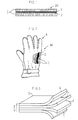
- Fig. 1 schematically shows a section through one embodiment of the material (an aggregate consisting of several strata) 33 for use in an electric heating device 34 (cf. Figs. 2 and 9) according to the present invention as described hereinbelow, for example in a garment, a container, an underlay blanket for accident victims, and so on.
- the aggregate is formed from, or contains, at least a first stratum 1 which consists of or includes at least one layer of an electrically conductive polymer with PTC properties.
- the first stratum 1 is disposed adjacent and, as a rule, connected to a second stratum 2 included in the aggregate and consisting of a thin film battery 5 or a thin film accumulator 5.
- a first stratum 1 which consists of or includes at least one layer of an electrically conductive polymer with PTC properties.
- the first stratum 1 is disposed adjacent and, as a rule, connected to a second stratum 2 included in the aggregate and consisting of a thin film battery 5 or a thin film accumulator 5.
- the aggregate generally includes protective layers 3 disposed on either side of the two strata 1, 2 and consisting, for example, of plastic material, metal such as metal foil or textile material, or of a combination of two or more of these materials.
- protective layers 3 disposed on either side of the two strata 1, 2 and consisting, for example, of plastic material, metal such as metal foil or textile material, or of a combination of two or more of these materials.
- Fig. 2 shows one example of an application of the present invention in which the device 34 is designed as a heating glove 4 for, for example, rheumatics.
- Fig. 3 shows an example of a thin film battery 5 or a thin film accumulator 5 of a type which is advantageously employed in the practical application of the present invention.
- the thin film battery 5 there is included a lithium layer 6 acting as negative pole, a subjacent polymer composite layer 7 acting as electrolyte, a composite layer 8 acting as positive pole and an electric conductor 9 connected to the composite layer 8.
- a thin film battery is not much thicker than normal letter paper, approx. 0.2 mm.
- the composite layer 8 consists of a mixture of the electrolyte and a compound which readily entraps lithium ions (e.g. vanadium oxide).
- the lithium ions pass through the electrolyte to the composite layer 8 (the positive pole), while the electrons take the outer path from the lithium layer 6 (the negative pole) to the composite layer 8, i.e. go via an outer load (not shown) and the electric conductor 9.
- the load constitutes a resistor heating unit and will be described hereinbelow. Both the ions and the electrons are stored in the composite layer 8 and pass back to the lithium layer 6 when the battery is recharged.
- Thin film batteries of this type may be purchased from various commercial sources, e.g. the Japanese firm Yuasa Battery, the Canadian firm Hydro Quebec and the Japanese firm Sharp Corporation.
- Examples of literature in which this type of thin film battery is described is the book published by Elsevier Science Publishers B.V. in 1991 entitled “Chemistry and Energy-I", C.A.C. Segueira (editor) which includes on pp. 153-162, an article written by Jorgen S. Lundsgaard et al "The All-Solid-State Lithium Polymer Electrolyte Battery", and on pp. 163-175 includes an article written by M.A.G. Martins et al "All-Solid-State Thin-Film Polymer Electrolyte Batteries".
- Another example is Koksbang et al, “Rechargeability and Rate Capability of Polymer Electrolyte Batteries at Room Temperature", Journal of Power Sources, 32 (1990) pp. 175-185.
- the aggregate includes a heating unit in which is included a polymer material with PTC properties.
- a polymer material with PTC properties may be obtained from Neste Polymer Compounds AB, Sweden under the designation ET-Semicon CT 6422:70 or 6002:70. These materials are semiconductor thermoplastic materials. Another material which has been utilized in practical tests and which has been obtained from Norells Sweden AB is ET-Semicon CT 8711:70.
- cast electrodes Fig. 4a
- an electrode material screen-printed on the polymer layer Fig. 4b
- an electrode material applied to the polymer layer by a vacuum coating method Fig.
- a partly cast electrode material in the form of a lattice (Fig. 4d).
- the lattice-formed electrically conductive electrode material in Fig. 4d is, for example, cast on opposing sides of the polymer layer or connected to the polymer layer by gluing.
- the polymer layer has been given reference numeral 10 and the electrode material reference numeral 11.
- the electrode material is, in certain practical applications, connected to the polymer material 10 by a welding process.
- a thin film battery of the type which is to be preferred in the present invention has preferably an average voltage of 2.4 V/polymer layer.
- a number of layers (cf. Figs. 5-7) are generally laminated.
- Vacuum technique is employed in one preferred production technology for laminating the various thin film accumulators or batteries.
- the different layers are placed on one another, a series connection of the different batteries being obtained in that the positive and negative poles of adjacent batteries are connected to one another, whereafter the layer of batteries is compressed and vacuum sealed.
- the sealing material consists, in one preferred embodiment, of an aluminium foil whose inside is coated with a layer of an electrically insulating material, for example polyethylene based hotmelt glue.
- Fig. 5 schematically illustrates one embodiment of the present invention in which a thin film battery 12 consisting of a plurality of strata is formed from ten mutually superposed and interconnected thin film batteries 5.
- the composite thin film battery 12 is connected by means of a conductor 13 to the one current distributor 11 in the electrically conductive polymer material layer 10.
- the negative pole of the composite thin film battery 12 is connected by means of a conductor 14 to a charger terminal 15 which, via a switch 17 and a conductor 18, is connected to a second current distributor 11' in the electrically conductive polymer layer 10.
- Both of the current distributors 11 and 11' are located a distance from one another which is determined by the electric and thermal properties of the polymer layer and by the thermal effect which is to be emitted by the polymer disposed between the current distributors.
- the current distributors 11,11' and the polymer layer 10 constitute the heating unit 19 of the device.
- the charging terminal 15 is, via a conductor 16, connected to the one current distributor 11.
- a charger is connected to the charging terminal 15, the positive poles and negative poles of the device are thereby coupled to corresponding poles in the thin film battery 12 consisting of a plurality of layers.
- the electrically conductive polymer layer 10 is, for example, of the ET-Semicon make with commercial designation CT 6002:17.
- the two electrodes or current distributors 11,11' consist, for example, of wire-like electric conductors which are cast in the polymer layer or are formed from a metal foil or alternatively synthetic metal foil, e.g. ICP material (Intrinsically Conductive Polymers).
- the wire-formed conductors have, in one preferred embodiment, a diameter of 0.9 mm and metal foil thickness of 25 um.
- the accumulator 12 consisting of a plurality of strata is cast in or sealed against the surroundings by an electrically insulating, water resistant and water impermeable material in applications in which the thin film batteries 5 are sensitive to moisture.
- the polymer material layer 10 needs no corresponding protection.
- the heating layer 10 and the thin film accumulator 12 are discrete from one another, the advantage will be afforded that the accumulator can be replaced.
- the electric connections 13,14,16,18 between the battery and the heating unit are conductive, body movements on the part of the wearer will be facilitated.
- One major advantage in the employment of an electrically conductive material of the PTC type is that the heating effect can be locally regulated, i.e. colder positions emit more heat than warmer positions. This regulation is automatic as a result of the PTC properties of the material.
- Figs. 6a and 6b show yet a further embodiment.
- the electrically conductive polymer layer 20 with PTC properties included in the heating unit 19 by screen printing has been provided with a first batch of electrodes 21 and a second batch of electrodes 22.
- the two electrode batches are disposed such that the electrodes are in spaced apart relationship from one another.
- the first batch of electrodes 21 has a projecting contact element 23 and the second batch of electrodes 22 has a projecting contact element 24.
- the heating unit 19 is glued with an electrically insulating glue against the positive pole layer 25 of a thin film battery 26 composed of a plurality of thin film batteries 5.
- electrically insulating glue for this purpose, use may be made of ABLEBOND 958-11 from Sikema AB.
- a switch 27 which, with conductors 28,29, is connected to the terminal 23 and negative connection 30, respectively, of the composite thin film battery 26.
- the positive connection 25 is, by the intermediary of a contact element 35 projecting from the battery 26, electrically connected to the contact element 24 of the second batch.
- a recharge terminal 31 with associated conductors 32,38.
- the electrically insulating glue employed in Figs. 6a and 6b use is made, in certain applications, of a generally thin electrically insulating film of plastic material, for example polyethylene or the like, which is fixed, e.g. fused to the surface of the electrically conductive polymer layer 20 turned to face towards the heating unit 19.
- the film of plastic material covers the entire major surface of the polymer layer 20.
- the film fixed to the heating unit 19 is generally bonded (e.g. welded or glued) with the protective material which surrounds other parts of the composite battery 26.
- the polymer portion forms a part of the protective sealing of the battery, at the same time as the thermal generation of the polymer increases the usable proportion of the energy power content of the battery.
- this embodiment makes it possible that the thermal generating portion of the heating device can be placed in the immediate vicinity of that body or that space which is to be heated.
- a major advantage inherent in this embodiment is that the aggregate 33 formed from the heating unit 19 and the thin film battery 26 is suitable for mass production in running series for later cutting into units. After the cutting operation, the cut part is generally enclosed in an electrically insulating casing which also protects against water and water vapour.
- Figs. 7a and 7b show yet a further embodiment of a heating device 34 in which is included the heating unit 19 formed by the electrically conductive polymer layer 40 and a number of mutually adjacent thin film batteries 5 forming a composite thin film battery 45.
- the current is passed through the polymer layer 40 substantially parallel with the two defining surfaces 54,55 of the polymer layer from the first defining surface 54 to the second defining surface 55 of the polymer layer 40. This is achieved in that one or more electrode bands 41 and 43, respectively, abut against the first defining surface 54 and second defining surface 55, respectively, of the polymer layer 40.
- the electrode bands are, as a rule, separated at each such surface by electrically insulating layers 42,44 which extend between mutually adjacent electrodes.
- the surfaces 54,55 of the polymer layer 40 are thereby electrically insulated between the electrode bands 41,43.
- the insulating layers 42 and 44 are provided so as to prevent electron migration transversly through the polymer down to the conductive layer of the composite thin film battery 45. Instead, the sought-for more horizontally directed current will be obtained through the polymer, which gives uniform heat.
- the thin film battery pack 45 has its positive pole 46 combined with the polymer layer 40 so that electric contact exists between the electrode band or electrode bands 41, respectively, and the positive pole layer 46 at the battery pack.
- the positive pole layer 46 is provided with a projecting contact strip 47.
- the electrode band or the electrode bands 43, respectively are, via a switch 48, connected to the negative pole 49 of the thin film battery 45.
- a recharge terminal 50 which, with conductors 51,52 is connected to the negative pole 49 and the contact plate 47, respectively, projecting from the positive pole 46.
- an electrically conductive plastic ET-Semicon with the type designation CT 6422:70 or CT 6002:70.
- Application of the electrode bands 41,43 is, for example, effected using a technique corresponding to that described in the foregoing, for example by screen printing, gluing or vacuum coating.
- the whole of the outside of the resistor unit 40 is covered with a generally thin electrode layer 53.
- the whole of the inside of the polymer material 40 is, in certain embodiments, coated with thin electrically conductive material.
- a generally thin electrically insulating film of plastic material for example polyethylene or the like, is fixed, for example fused to the surface of the electrically conductive polymer layer 40 facing towards the heating unit 19, while in other embodiments, such film is absent.
- the film of plastic material covers the entire major surface of the polymer layer 40, in which event the positive pole of the battery is electrically connected to the electrodes 41 by a separate lead wiring (not shown in the figures).
- the film bonded to the heating unit 19 is generally joined (e.g.
- the film is absent, moisture protection is obtained in that the casing or housing surrounds both the heating unit 19 and the battery (cf. also Fig. 9 below). Where the film is absent, the above-mentioned lead wiring to the positive pole of the battery is not required.
- the heat generation of the polymer increases the extractable proportion of the energy power content of the battery.
- this embodiment makes it possible for the heat generating portion of the heating device to be placed in the immediate proximity of that body or that space which is to be heated.
- the aggregate 33 formed by the heating unit 19 and the thin film battery 45 is suitable for mass production on a production line for later cutting into units, in particular in the embodiment in which the insulating plastic layer between the resistor unit and the battery is not employed.
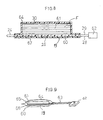
- Figs. 8-9 illustrate various conceivable embodiments and placements of the resistor heating unit 60, the thin film battery 61 and the operating unit 62.
- Fig. 8 shows one embodiment in which the polymer layer 60 of the resistor heating unit 19 and the thin film battery 61 are physically interconnected with one another and, in one preferred version, are included in a laminate.
- the operating unit 62 is disposed at a separate position and electrically connected by the intermediary of conductors 28,29 with the polymer layer 60 and the negative pole 30 of the thin film battery 61, respectively, of the composite unit in which the resistor unit 19 and the thin film battery 61 are included.
- an electrically insulating and water-impermeable plastic material layer 67 e.g. a polythene layer, is disposed between the electrically conductive polymer layer 60 of the heating unit 19 and the battery 61 in order to provide a particularly good moisture seal about the battery 61.
- This plastic material layer 67 is fused with the water and water vapour-impermeable casing 64 which surrounds the remaining portions of the composite battery 61.
- This design corresponds to the design in Figs. 6a and 6b, but with the difference that the plastic material layer 67 has been applied onto the pole layers 25, before the electrically conductive polymer layer (or resistor layer) 20 with its conductors 21,22 has been mounted in place.
- Fig. 6a and 6b This design corresponds to the design in Figs. 6a and 6b, but with the difference that the plastic material layer 67 has been applied onto the pole layers 25, before the electrically conductive polymer layer (or resistor layer) 20 with its conductors 21,22 has been mounted in place.
- the contact element 24 is connected to the positive pole layer 25. Furthermore, the negative pole connection 30 is, via the insulating conductor 29, electrically connected to the operating unit 62 which is also electrically connected to the second connection of the heating unit 19 and, thereby, the contact element 24 via the conductor 28.
- This version may advantageously be employed where the requirement on mobility is less severe, for example in sole inlays.
- Fig. 9 illustrates yet a further embodiment in which the pole layer 65 of the thin film battery 61 is in directly conductive contact with an electrode material layer 66 connected to the electrically conductive polymer layer 60 of the heating unit 19.
- This combination of thin film battery 61 and heating unit 69 forms, for example, a laminate and is illustrated, in this drawing Figure, enclosed in a moisture-proof and waterproof casing 64.
- the operating unit 62 is, in Fig. 9, shown as disposed outside the casing 64 and connected with the heating element via the conductors 63.
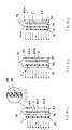
- Figs. 10a-c show schematic partial sections of combinations of the heating element 1 and thin film batteries 2 designed in accordance with that described in the foregoing.
- the letter A is taken to signify thermal energy which is in motion in a direction from the heating element 1 and towards a body or a space which is to be heated.
- the heating element 1 is disposed between the thin film battery 2 and the above-mentioned body or space.
- the combinations illustrated in the figures also include a casing 64 whose one wall 64a is located on that side of the thin film battery 2 which is turned to face away from the body or the space which is to be heated.
- the other wall 64b of the casing is located on the opposite side of the thin film battery 2. Both of the walls are closely united with one another by means of a closure 70 in the edge region of the thin film battery 2.
- Both of the walls of 64a,b of the casing are substantially parallel with the major surfaces 36,37 of the thin film battery.
- Figs. 10a-c the heating element 1, the thin film battery 2 and both walls 64a,b of the casing are shown as disposed in spaced apart relationship.
- spacer elements are provided for maintaining these spacings, in particular embodiments in which the device is to form a mechanically rigid unit.
- the heating element 1, the thin film battery 2 and the walls 64a,b are moveable towards and away from one another while being fixed in relation to one another at regular distances.
- Fig. 10d shows a partial magnification of the marked region in Fig. 10a.
- the wall 64a of the casing is, in the illustrated embodiment, composed of a metal foil 68 consisting of one or more layers and a plastic layer 69 on either side of the metal foil.
- the metal foil is preferably coated with the plastic layers.
- Figs. 10a and 10b show embodiments in which the casing 64 in Fig. 10a surrounds only the thin film battery 2 and in which the casing 64 in Fig. 10b surrounds both the thin film battery 2 and the heating element 1.
- Fig. 10c shows one embodiment in which a layer 71 of electrically insulating material which, in addition, is impermeable to both moisture and water, is disposed between the heating element 1 and the thin film battery 2.
- the material in the layer 71 is of poor thermal insulation or otherwise expressed, good thermal permeability.
- the wall 64 of the casing is sealingly connected with the layer.
- the thermal energy is reflected by the metal foil 68 back towards the battery 2, whereby this receives elevated temperature which, in turn, makes it possible for a greater portion of the energy power content of the battery to be available to be converted into thermal energy in the heating element 1.
- the band constitutes an intermediate product from which is separated portions or part lengths adapted to the requirements of the pertinent practical application.
- the length of the separated part is adaptable to the relevant practical application, but also the form of that part which is cut off.
- the size of the separated part or the separated portion is adapted in accordance with the power/energy need which the particular application requires.
- the construction of the present invention entails that it is possible beforehand to determine the desired generated output per surface unit by dimensioning the battery for a given pole voltage (number of partial batteries 5), selecting polymer material with a certain volume resistivity and/or selecting a certain electrode spacing.
- the layer thickness of the polymer material is also determinative of the power output per surface unit. There will hereby be obtained a predetermined operational time of that device in which the separated part is included, irrespective of the surface area of the separated part.
- the band is provided with a contact plate for electric contact between heating unit, thin film battery and operating unit, in which event the contact plates abut against the positive or negative poles of the thin film battery.
- the separated part is thereby simply interconnectable with an operating unit 27,48,62, e.g. as described above with particular reference to Fig. 9.
- the cut portion is generally enclosed in an electrically insulating casing which is also water and water vapour proof. Requisite conductors for, for example, the operating unit and battery charger are sealingly lead through the casing.
- the aggregate 33 includes a number of strata which are disposed adjacent one another.
- the expression "disposed adjacent one another” encompasses a multiplicity of embodiments, for example that the strata are continuously interconnected, that they are discontinuously interconnected, that they are laminated, that they are loosely disposed in relation to one another in portions which are followed by sections where they are interconnected with one another, that they are only interconnected with one another at points, that only two layers out of three are interconnected with one another within a given area, that the layers are interconnected with one another in but the edge regions of, for example, a band, that the strata are laid with the major surfaces facing one another about, for example, a body and are kept in place by outer fixing devices, that the strata are compressed in that a surrounding protective casing is wholly or partly evacuated of its gas content, etc.
- thin film battery has been employed. This is taken to signify both rechargeable thin film batteries and non-rechargeable batteries (primary batteries). The type of battery is adapted to suit the particular practical application in which the present invention is employed.
- the resistor heating unit 19 consists solely of an electrically conductive polymer layer 1.10,20,40,60
- the heating unit 19 is provided, in other embodiments, with more than one electrically conductive polymer layer.
- the device is designed so as to constitute a rigid and mechanically stable unit, for example be designed as a container. In other practical applications, the device is designed so as to form a flexible and bendable unit. Depending upon those requirements placed by the relevant practical application, the device includes material which entails that the thus formed aggregate 33 is bendable, extendable, elastic, resiliently yieldable, mechanically stable etc.
Landscapes
- Engineering & Computer Science (AREA)
- Health & Medical Sciences (AREA)
- Textile Engineering (AREA)
- Chemical & Material Sciences (AREA)
- Chemical Kinetics & Catalysis (AREA)
- Electrochemistry (AREA)
- General Chemical & Material Sciences (AREA)
- Manufacturing & Machinery (AREA)
- General Health & Medical Sciences (AREA)
- Biomedical Technology (AREA)
- Environmental & Geological Engineering (AREA)
- Public Health (AREA)
- Heart & Thoracic Surgery (AREA)
- Animal Behavior & Ethology (AREA)
- Life Sciences & Earth Sciences (AREA)
- Veterinary Medicine (AREA)
- Vascular Medicine (AREA)
- Physical Education & Sports Medicine (AREA)
- Microelectronics & Electronic Packaging (AREA)
- Surface Heating Bodies (AREA)
- Resistance Heating (AREA)
- Sealing Battery Cases Or Jackets (AREA)
- Saccharide Compounds (AREA)
- Air-Conditioning For Vehicles (AREA)
Abstract
Description
- The present invention relates to a heating device according to the preamble of the independent claim.
- Within many fields of activity, it is desirable to heat different parts of the body, for example for medical purposes or for reasons of comfort. One example is the heating of joints, hands and other parts of the body of rheumatism sufferers. Another example is within the areas of sports and leisure activities where proposals have been put forward for heated gloves, shoe inlays and other items of clothing as well as sleeping-bags.
- It is also desirable in the art to devise containers which, on transport or power failure, maintain an elevated temperature in their storage space. Similarly, there are needs for substrates which, on transport or power failure, maintain an elevated temperature, for example to avoid the risk that the temperature falls in accumulators or batteries placed on the substrates - which could lead to a reduction in the quantity of energy which can be extracted from them.
- To cover these needs numerous solutions have been proposed in the art, these all being based on electric heating with the aid of various resistor heating elements and electric energy sources, normally accumulators or dry cell batteries. As examples of this known technology, mention might be made of Swedish patent application No. 8402743-2 which describes a glove intended for rheumatics with inlaid resistor wires and a current source so as to develop a thermal effect exceeding 25 W in the glove.
- In a corresponding manner, Swedish patent application No. 8404783-6 describes a medical undergarment with inlaid resistor heating elements and a current source in the form of a battery. Electrically heated shoe inlays are described, for instance, in the two German specifications DE-A-3 904 603 and DE-C-4 000 259. These shoe inlays have inlaid resistor heating elements which are connectable to a battery or other source of electric energy. In both cases, the resistor heating elements are in the form of printed conductor paths on a base consisting of plastic or other non-conductive material. In both cases, the heating proper is also controlled by means of electric circuit connections so as to as avoid overheating.
- As was mentioned above, it is known in the leisure-time sector to make use of electrically heated sleeping-bags or garments. One example is disclosed in US-A-3,443,066 which describes a sleeping-bag or other clothing garment of flexible, thermally insulating material with inlaid resistor heating wires and batteries for electric power supply.
- In automotive engineering, similar ideas have been employed, for example to provide heating elements for vehicle seats, an employment which necessitates a degree of give in the inlaid resistor heating elements. One example of this technique is described in SE-B-434 204 (7713250-4), in which the give or extensibility has been achieved by the inlay of meandering loops of resistor heating wires or tapes in a layer in the padding material of the seat.
- Yet a further a example of textile material which can be heated electrically is to be found in US-A-4,845,343 in which the resistor wires have been woven into the fabric structure proper.
- All of these prior art apparatuses and devices for heating larger or smaller parts of the body of a patient or general user suffer from numerous common drawbacks. One such drawback is that the prior art resistor heating elements consume considerable quantities of power and are, therefore, expensive in operation. Another drawback is that the possibilities of regulating the heating effect locally, i.e. within a limited part of the body are poor - in other words the user must choose between either a heating effect which gives satisfactory heating of the coldest part of the body which at the same time results in overheating of other parts of the body, or a heating effect which provides comfortable heating of the major part of the body but insufficient heating within certain other parts of the body. A further drawback inherent in many of the prior art apparatuses is that they require separate accumulators whose capacity is often reduced at low temperatures, since they must be carried at relatively unprotected positions in the wearer's clothing. Moreover, the separate accumulators must be carried in some type of belt or the like which may prove unwieldy. Another drawback is that some type of external thermostat is necessary in order to be able to obtain a determined average temperature.
- WO 87/01549 discloses a heater in the form of an insulated conductive plastic element with embedded braided electrodes electrically connected with a conventional encased car or boat battery. The heater is wrapped around the encased battery for maintaining a constant temperature in the battery for improved performance, however this configuration is hardly suitable for use in clothing garments.
- One object of the present invention is, therefore, to realize an electric heating device, for example designed as a panel, a laminate, a band, a container etc, in which device one or more of the drawbacks inherent in prior art technology have been obviated. For example, the device according to the present invention should be suitable to be included in a garment.
- A further object of the present invention is to realize a device, an arrangement or an article, for example a garment of clothing, of a design which entails that the heating effect varies locally in response to the local heating requirement.
- Yet a further object of the present invention is to render the heating device so thin and flexible that it can be inlaid between two textile layers in a garment of clothing or the like without the appearence or other properties thereof being appreciably altered. Still a further object of the present invention is to devise automatic regulation of the average temperature without the need of an external thermostat. Yet a further object of the present invention is to realize a heating device which includes an electric power source which cooperates with a heating element included in the heating device so as to avoid or counteract the eventuality that the available portion of the capacity of the power source is reduced as a result of cooling of the energy source and, instead, even to increase the available capacity of the energy source in that heat generated in the immediate proximity of the energy source raises the temperature of the energy source. Still a further object of the present invention is to realize reflection of heat towards the energy source by particular placing of the energy source.
- These and other objects of the present invention will be attained if the heating device is designed in accordance with the disclosures in the characterizing clause of appended
claim 1. - The appended subclaims disclose expedient embodiments of the present invention.
- The heating element is to consist of a polymer material with so-called PTC properties (Positive Temperature Coefficient), in particular an electrically conducted thermoplastic material such as conductive, butyl inoculated polyethylene.
- The thin film accumulator may advantageously consist of an accumulator which is of the lithium type and has a number of mutually stratified layers, a lithium layer, a polymer electrolyte layer, a vanadinoxide composite layer and a conductor layer.
- The electrode material most suitably consists of a conductor material which has been united with the heating element by casting, screen printing, gluing with electrically conductive glue or vacuum coating in a suitable pattern so as to make possible electric connection to the thin film accumulator.
- The control circuit may be as simple as a conductive path with a connected switch between the two poles of the accumulator, but is preferably a control circuit with circuit elements for sensing and controlling the accumulator status and possibly also time limiting for activation time.
- The expression "garment" is here taken to signify not only clothing garments such as gloves, waistcoats and the like, but also shoe inlays, sleeping-bags or seat heaters or cushions, for example for leisure time activity purposes.
- The present invention will now be described in greater detail hereinbelow, with particular reference to the accompanying drawings which show embodiments of the present invention. In the accompanying drawings:
- Fig. 1
- shows a section through one embodiment of an assembly for use in a heating device according to the present invention;
- Fig. 2
- shows an example of a garment which is designed according to the present invention;
- Fig. 3
- schematically illustrates a preferred thin film accumulator for use in the present invention;
- Figs. 4a-d
- show four examples of different methods of uniting electrode material and heating foil material;
- Fig. 5
- schematically illustrates a first example of how the heating foil material and thin film accumulator may be united;
- Figs. 6a,b
- schematically illustrate a second example of how the heating foil material and thin film accumulator may be united;
- Figs. 7a,b
- schematically illustrate a third example of how heating foil material and thin film accumulator may be united;
- Figs. 8-9
- schematically illustrate further examples of heating units which may be used in practical application of the nresent invention; and
- Figs. 10a-d
- schematically illustrate examples of heating units provided with a heat reflecting layer.
- Fig. 1 schematically shows a section through one embodiment of the material (an aggregate consisting of several strata) 33 for use in an electric heating device 34 (cf. Figs. 2 and 9) according to the present invention as described hereinbelow, for example in a garment, a container, an underlay blanket for accident victims, and so on. The aggregate is formed from, or contains, at least a
first stratum 1 which consists of or includes at least one layer of an electrically conductive polymer with PTC properties. Thefirst stratum 1 is disposed adjacent and, as a rule, connected to asecond stratum 2 included in the aggregate and consisting of athin film battery 5 or athin film accumulator 5. As is apparent from the embodiment illustrated in Fig. 1, the aggregate generally includes protective layers 3 disposed on either side of the twostrata third strata - Fig. 2 shows one example of an application of the present invention in which the
device 34 is designed as aheating glove 4 for, for example, rheumatics. - Fig. 3 shows an example of a
thin film battery 5 or athin film accumulator 5 of a type which is advantageously employed in the practical application of the present invention. In the illustrated embodiment of thethin film battery 5, there is included alithium layer 6 acting as negative pole, a subjacent polymer composite layer 7 acting as electrolyte, a composite layer 8 acting as positive pole and an electric conductor 9 connected to the composite layer 8. Such a thin film battery is not much thicker than normal letter paper, approx. 0.2 mm. The composite layer 8 consists of a mixture of the electrolyte and a compound which readily entraps lithium ions (e.g. vanadium oxide). The lithium ions pass through the electrolyte to the composite layer 8 (the positive pole), while the electrons take the outer path from the lithium layer 6 (the negative pole) to the composite layer 8, i.e. go via an outer load (not shown) and the electric conductor 9. The load constitutes a resistor heating unit and will be described hereinbelow. Both the ions and the electrons are stored in the composite layer 8 and pass back to thelithium layer 6 when the battery is recharged. - Thin film batteries of this type may be purchased from various commercial sources, e.g. the Japanese firm Yuasa Battery, the Canadian firm Hydro Quebec and the Japanese firm Sharp Corporation. Examples of literature in which this type of thin film battery is described is the book published by Elsevier Science Publishers B.V. in 1991 entitled "Chemistry and Energy-I", C.A.C. Segueira (editor) which includes on pp. 153-162, an article written by Jorgen S. Lundsgaard et al "The All-Solid-State Lithium Polymer Electrolyte Battery", and on pp. 163-175 includes an article written by M.A.G. Martins et al "All-Solid-State Thin-Film Polymer Electrolyte Batteries". Another example is Koksbang et al, "Rechargeability and Rate Capability of Polymer Electrolyte Batteries at Room Temperature", Journal of Power Sources, 32 (1990) pp. 175-185.
- According to the present invention, the aggregate includes a heating unit in which is included a polymer material with PTC properties. One such particularly suitable material may be obtained from Neste Polymer Compounds AB, Sweden under the designation ET-Semicon CT 6422:70 or 6002:70. These materials are semiconductor thermoplastic materials. Another material which has been utilized in practical tests and which has been obtained from Norells Sweden AB is ET-Semicon CT 8711:70. For connecting these electrically
conductive polymer materials 10 with PTC properties, use is made of, for example, cast electrodes (Fig. 4a) an electrode material screen-printed on the polymer layer (Fig. 4b), an electrode material applied to the polymer layer by a vacuum coating method (Fig. 4c), or a partly cast electrode material in the form of a lattice (Fig. 4d). It will be obvious to a person skilled in the art that other connection techniques are also applicable within the framework of the present invention. The lattice-formed electrically conductive electrode material in Fig. 4d is, for example, cast on opposing sides of the polymer layer or connected to the polymer layer by gluing. In Figs. 4a-d, the polymer layer has been givenreference numeral 10 and the electrodematerial reference numeral 11. In the embodiments illustrated in Figs. 4b and 4c, the electrode material is, in certain practical applications, connected to thepolymer material 10 by a welding process. - A thin film battery of the type which is to be preferred in the present invention has preferably an average voltage of 2.4 V/polymer layer. In order to obtain a sufficiently high voltage, a number of layers (cf. Figs. 5-7) are generally laminated. In one expedient embodiment of the present invention, use is made, for example, of ten laminated layers of batteries, in which event a polar voltage of 24 V is obtained. Vacuum technique is employed in one preferred production technology for laminating the various thin film accumulators or batteries. The different layers are placed on one another, a series connection of the different batteries being obtained in that the positive and negative poles of adjacent batteries are connected to one another, whereafter the layer of batteries is compressed and vacuum sealed. The sealing material consists, in one preferred embodiment, of an aluminium foil whose inside is coated with a layer of an electrically insulating material, for example polyethylene based hotmelt glue.
- Fig. 5 schematically illustrates one embodiment of the present invention in which a
thin film battery 12 consisting of a plurality of strata is formed from ten mutually superposed and interconnectedthin film batteries 5. The compositethin film battery 12 is connected by means of aconductor 13 to the onecurrent distributor 11 in the electrically conductivepolymer material layer 10. The negative pole of the compositethin film battery 12 is connected by means of aconductor 14 to acharger terminal 15 which, via aswitch 17 and aconductor 18, is connected to a second current distributor 11' in the electricallyconductive polymer layer 10. Both of thecurrent distributors 11 and 11' are located a distance from one another which is determined by the electric and thermal properties of the polymer layer and by the thermal effect which is to be emitted by the polymer disposed between the current distributors. Thecurrent distributors 11,11' and thepolymer layer 10 constitute theheating unit 19 of the device. - The charging
terminal 15 is, via aconductor 16, connected to the onecurrent distributor 11. When a charger is connected to the chargingterminal 15, the positive poles and negative poles of the device are thereby coupled to corresponding poles in thethin film battery 12 consisting of a plurality of layers. - The electrically
conductive polymer layer 10 is, for example, of the ET-Semicon make with commercial designation CT 6002:17. The two electrodes orcurrent distributors 11,11', consist, for example, of wire-like electric conductors which are cast in the polymer layer or are formed from a metal foil or alternatively synthetic metal foil, e.g. ICP material (Intrinsically Conductive Polymers). The wire-formed conductors have, in one preferred embodiment, a diameter of 0.9 mm and metal foil thickness of 25 um. Theaccumulator 12 consisting of a plurality of strata is cast in or sealed against the surroundings by an electrically insulating, water resistant and water impermeable material in applications in which thethin film batteries 5 are sensitive to moisture. Thepolymer material layer 10 needs no corresponding protection. In this embodiment in which theheating layer 10 and thethin film accumulator 12 are discrete from one another, the advantage will be afforded that the accumulator can be replaced. In that theelectric connections - One major advantage in the employment of an electrically conductive material of the PTC type is that the heating effect can be locally regulated, i.e. colder positions emit more heat than warmer positions. This regulation is automatic as a result of the PTC properties of the material.
- Figs. 6a and 6b show yet a further embodiment. In this case, the electrically
conductive polymer layer 20 with PTC properties included in theheating unit 19 by screen printing has been provided with a first batch ofelectrodes 21 and a second batch ofelectrodes 22. The two electrode batches are disposed such that the electrodes are in spaced apart relationship from one another. The first batch ofelectrodes 21 has a projectingcontact element 23 and the second batch ofelectrodes 22 has a projectingcontact element 24. Theheating unit 19 is glued with an electrically insulating glue against thepositive pole layer 25 of athin film battery 26 composed of a plurality ofthin film batteries 5. As electrically insulating glue for this purpose, use may be made of ABLEBOND 958-11 from Sikema AB. For connecting and disconnecting the unit, there is aswitch 27 which, withconductors negative connection 30, respectively, of the compositethin film battery 26. Thepositive connection 25 is, by the intermediary of acontact element 35 projecting from thebattery 26, electrically connected to thecontact element 24 of the second batch. For recharging, there is arecharge terminal 31 with associatedconductors - As an alternative to the electrically insulating glue employed in Figs. 6a and 6b use is made, in certain applications, of a generally thin electrically insulating film of plastic material, for example polyethylene or the like, which is fixed, e.g. fused to the surface of the electrically
conductive polymer layer 20 turned to face towards theheating unit 19. As a rule, the film of plastic material covers the entire major surface of thepolymer layer 20. In the embodiments in which thecomposite battery 26 needs protection against moisture (water vapour or water) the film fixed to theheating unit 19 is generally bonded (e.g. welded or glued) with the protective material which surrounds other parts of thecomposite battery 26. Hereby, the polymer portion forms a part of the protective sealing of the battery, at the same time as the thermal generation of the polymer increases the usable proportion of the energy power content of the battery. In addition, this embodiment makes it possible that the thermal generating portion of the heating device can be placed in the immediate vicinity of that body or that space which is to be heated. - A major advantage inherent in this embodiment is that the aggregate 33 formed from the
heating unit 19 and thethin film battery 26 is suitable for mass production in running series for later cutting into units. After the cutting operation, the cut part is generally enclosed in an electrically insulating casing which also protects against water and water vapour. - Figs. 7a and 7b show yet a further embodiment of a
heating device 34 in which is included theheating unit 19 formed by the electricallyconductive polymer layer 40 and a number of mutually adjacentthin film batteries 5 forming a compositethin film battery 45. In this case, the current is passed through thepolymer layer 40 substantially parallel with the two definingsurfaces surface 54 to the second definingsurface 55 of thepolymer layer 40. This is achieved in that one ormore electrode bands surface 54 and second definingsurface 55, respectively, of thepolymer layer 40. When more than oneelectrode band surfaces layers surfaces polymer layer 40 are thereby electrically insulated between theelectrode bands thin film battery 45. Instead, the sought-for more horizontally directed current will be obtained through the polymer, which gives uniform heat. - The thin
film battery pack 45 has itspositive pole 46 combined with thepolymer layer 40 so that electric contact exists between the electrode band orelectrode bands 41, respectively, and thepositive pole layer 46 at the battery pack. Thepositive pole layer 46 is provided with a projectingcontact strip 47. As will be apparent from Fig. 7b the electrode band or theelectrode bands 43, respectively, are, via aswitch 48, connected to thenegative pole 49 of thethin film battery 45. In order to make possible recharge, there is disposed arecharge terminal 50 which, withconductors negative pole 49 and thecontact plate 47, respectively, projecting from thepositive pole 46. - As material for the
polymer layer 40, use is advantageously made in this embodiment of an electrically conductive plastic ET-Semicon with the type designation CT 6422:70 or CT 6002:70. Application of theelectrode bands electrode bands 43 to one another, preferably the whole of the outside of theresistor unit 40 is covered with a generallythin electrode layer 53. Also the whole of the inside of thepolymer material 40 is, in certain embodiments, coated with thin electrically conductive material. - In certain practical applications, in the embodiment illustrated in Figs. 7a and 7b, a generally thin electrically insulating film of plastic material, for example polyethylene or the like, is fixed, for example fused to the surface of the electrically
conductive polymer layer 40 facing towards theheating unit 19, while in other embodiments, such film is absent. As a rule, the film of plastic material covers the entire major surface of thepolymer layer 40, in which event the positive pole of the battery is electrically connected to theelectrodes 41 by a separate lead wiring (not shown in the figures). In those embodiments in which thecomposite battery 45 needs protection against moisture (water vapour or water) and in which the film occurs, the film bonded to theheating unit 19 is generally joined (e.g. welded or glued) to the protective material which surrounds other parts of thecomposite battery 45. In embodiments in which the film is absent, moisture protection is obtained in that the casing or housing surrounds both theheating unit 19 and the battery (cf. also Fig. 9 below). Where the film is absent, the above-mentioned lead wiring to the positive pole of the battery is not required. In both of the embodiments, the heat generation of the polymer increases the extractable proportion of the energy power content of the battery. Moreover, this embodiment makes it possible for the heat generating portion of the heating device to be placed in the immediate proximity of that body or that space which is to be heated. - Also in embodiments described in the preceding paragraphs, the aggregate 33 formed by the
heating unit 19 and thethin film battery 45 is suitable for mass production on a production line for later cutting into units, in particular in the embodiment in which the insulating plastic layer between the resistor unit and the battery is not employed. - Figs. 8-9 illustrate various conceivable embodiments and placements of the
resistor heating unit 60, thethin film battery 61 and the operatingunit 62. - Fig. 8 shows one embodiment in which the
polymer layer 60 of theresistor heating unit 19 and thethin film battery 61 are physically interconnected with one another and, in one preferred version, are included in a laminate. The operatingunit 62 is disposed at a separate position and electrically connected by the intermediary ofconductors polymer layer 60 and thenegative pole 30 of thethin film battery 61, respectively, of the composite unit in which theresistor unit 19 and thethin film battery 61 are included. - In the embodiment illustrated in Fig. 8, an electrically insulating and water-impermeable
plastic material layer 67, e.g. a polythene layer, is disposed between the electricallyconductive polymer layer 60 of theheating unit 19 and thebattery 61 in order to provide a particularly good moisture seal about thebattery 61. Thisplastic material layer 67 is fused with the water and water vapour-impermeable casing 64 which surrounds the remaining portions of thecomposite battery 61. This design corresponds to the design in Figs. 6a and 6b, but with the difference that theplastic material layer 67 has been applied onto the pole layers 25, before the electrically conductive polymer layer (or resistor layer) 20 with itsconductors contact element 24 is connected to thepositive pole layer 25. Furthermore, thenegative pole connection 30 is, via the insulatingconductor 29, electrically connected to the operatingunit 62 which is also electrically connected to the second connection of theheating unit 19 and, thereby, thecontact element 24 via theconductor 28. This version may advantageously be employed where the requirement on mobility is less severe, for example in sole inlays. - Fig. 9 illustrates yet a further embodiment in which the
pole layer 65 of thethin film battery 61 is in directly conductive contact with anelectrode material layer 66 connected to the electricallyconductive polymer layer 60 of theheating unit 19. This combination ofthin film battery 61 andheating unit 69 forms, for example, a laminate and is illustrated, in this drawing Figure, enclosed in a moisture-proof andwaterproof casing 64. The operatingunit 62 is, in Fig. 9, shown as disposed outside thecasing 64 and connected with the heating element via theconductors 63. - Figs. 10a-c show schematic partial sections of combinations of the
heating element 1 andthin film batteries 2 designed in accordance with that described in the foregoing. The letter A is taken to signify thermal energy which is in motion in a direction from theheating element 1 and towards a body or a space which is to be heated. In all of Figs. 10a-c, theheating element 1 is disposed between thethin film battery 2 and the above-mentioned body or space. The combinations illustrated in the figures also include acasing 64 whose onewall 64a is located on that side of thethin film battery 2 which is turned to face away from the body or the space which is to be heated. The other wall 64b of the casing is located on the opposite side of thethin film battery 2. Both of the walls are closely united with one another by means of aclosure 70 in the edge region of thethin film battery 2. Both of the walls of 64a,b of the casing are substantially parallel with themajor surfaces - In Figs. 10a-c the
heating element 1, thethin film battery 2 and bothwalls 64a,b of the casing are shown as disposed in spaced apart relationship. In certain practical applications, spacer elements (not shown in the figures) are provided for maintaining these spacings, in particular embodiments in which the device is to form a mechanically rigid unit. In other embodiments, for example when the device is included in a garment, theheating element 1, thethin film battery 2 and thewalls 64a,b are moveable towards and away from one another while being fixed in relation to one another at regular distances. - Fig. 10d shows a partial magnification of the marked region in Fig. 10a. It will be apparent from the partial magnification that the
wall 64a of the casing is, in the illustrated embodiment, composed of ametal foil 68 consisting of one or more layers and aplastic layer 69 on either side of the metal foil. The metal foil is preferably coated with the plastic layers. - Figs. 10a and 10b show embodiments in which the
casing 64 in Fig. 10a surrounds only thethin film battery 2 and in which thecasing 64 in Fig. 10b surrounds both thethin film battery 2 and theheating element 1. - Fig. 10c shows one embodiment in which a
layer 71 of electrically insulating material which, in addition, is impermeable to both moisture and water, is disposed between theheating element 1 and thethin film battery 2. In addition, the material in thelayer 71 is of poor thermal insulation or otherwise expressed, good thermal permeability. Thewall 64 of the casing is sealingly connected with the layer. - On use of the embodiments described in Figs. 10a-d, the thermal energy is reflected by the
metal foil 68 back towards thebattery 2, whereby this receives elevated temperature which, in turn, makes it possible for a greater portion of the energy power content of the battery to be available to be converted into thermal energy in theheating element 1. - In the description of Figs. 10a-d, use has been made of the general
expressions heating element 1 andthin film battery 2. This is hereby taken to signify that theelement battery - When the above-described embodiments of
thin film battery heating unit 19 which, as a rule, include an electrically insulating polymer material located between the thin film battery and the heating unit, are to be produced in the form of long bands, the advantage will be attained that the band constitutes an intermediate product from which is separated portions or part lengths adapted to the requirements of the pertinent practical application. However, it is obvious that not only the length of the separated part is adaptable to the relevant practical application, but also the form of that part which is cut off. - The size of the separated part or the separated portion is adapted in accordance with the power/energy need which the particular application requires. The construction of the present invention entails that it is possible beforehand to determine the desired generated output per surface unit by dimensioning the battery for a given pole voltage (number of partial batteries 5), selecting polymer material with a certain volume resistivity and/or selecting a certain electrode spacing. The layer thickness of the polymer material is also determinative of the power output per surface unit. There will hereby be obtained a predetermined operational time of that device in which the separated part is included, irrespective of the surface area of the separated part. As a rule, the band is provided with a contact plate for electric contact between heating unit, thin film battery and operating unit, in which event the contact plates abut against the positive or negative poles of the thin film battery. The separated part is thereby simply interconnectable with an operating
unit - In the foregoing description, it is disclosed that the aggregate 33 (material) includes a number of strata which are disposed adjacent one another. The expression "disposed adjacent one another" encompasses a multiplicity of embodiments, for example that the strata are continuously interconnected, that they are discontinuously interconnected, that they are laminated, that they are loosely disposed in relation to one another in portions which are followed by sections where they are interconnected with one another, that they are only interconnected with one another at points, that only two layers out of three are interconnected with one another within a given area, that the layers are interconnected with one another in but the edge regions of, for example, a band, that the strata are laid with the major surfaces facing one another about, for example, a body and are kept in place by outer fixing devices, that the strata are compressed in that a surrounding protective casing is wholly or partly evacuated of its gas content, etc.
- In the above description, the term thin film battery has been employed. This is taken to signify both rechargeable thin film batteries and non-rechargeable batteries (primary batteries). The type of battery is adapted to suit the particular practical application in which the present invention is employed.
- The description and the accompanying drawings show specific orientations of the poles of the thin film batteries. It will be obvious to the skilled reader of the specification that the disclosed orientations merely constitute examples of embodiments and that the thin film batteries in other embodiments have reverse orientation, entailing that the positive and negative poles have changed place.
- It will be obvious to the skilled reader that, even if embodiments have been described in the foregoing in which the
resistor heating unit 19 consists solely of an electrically conductive polymer layer 1.10,20,40,60, theheating unit 19 is provided, in other embodiments, with more than one electrically conductive polymer layer. - In certain practical applications of the present invention, the device is designed so as to constitute a rigid and mechanically stable unit, for example be designed as a container. In other practical applications, the device is designed so as to form a flexible and bendable unit. Depending upon those requirements placed by the relevant practical application, the device includes material which entails that the thus formed
aggregate 33 is bendable, extendable, elastic, resiliently yieldable, mechanically stable etc. - In the above description, use has occasionally been made of such designations as upper, lower, right, left etc. These designations have been employed solely to facilitate presentation of the invention. It will be obvious to a person skilled in the art that the described technique generally permits any optional orientation in space.
- The above-detailed description has referred to but a limited number of embodiments of the present invention, but it will be readily perceived by a person skilled in the art that the present invention encompasses a large number of embodiments without departing from the spirit and scope of the appended claims.
- Where technical features mentioned in any claim are followed by reference signs, those reference signs have been included for the sole purpose of increasing the intelligibility of the claims and accordingly, such reference signs do not have any limiting effect on the interpretation of each element identified by way of example by such reference signs.
Claims (10)
- Electric heating device (34) the device including an electric energy source (2,5,12,36,45,61) and a resistor heating unit (19) comprising a first material stratum (1,10,20,40,60) consisting of or comprising portions of electrically conductive polymer material with PTC properties and having a pair of mutually oppositely arranged major surfaces, in which the polymer material with PTC properties is united with electrode material (11,21,22,41,43) which electrically connects said electrically conductive polymer material to the energy source (2,5,12,26,45,61) and in which the heating device (34) includes a regulator unit (17,27,48,62) for regulating the current supply to the resistor heating unit (1,10,20,40,60), characterized in that the electric energy source (2,5,12,26,45,61) is designed as a thin film battery (2,5,12,26,45,61) also having a pair of mutually oppositely arranged major surfaces and comprising positive and negative poles in the form of layers (6,8,25,30,46,49) of the thin film battery; and that the material stratum (1,10,20,40,60) is connected to the thin film battery (2,5,12,26,45,61) such that the energy source and the resistor heating unit form a composed unit in which respectively one each of the major surfaces of said battery (2,5,12,26,45,61) and of said first material stratum (1,10,20,40,60) are turned to face towards one another.
- The heating device (34) as claimed in claim 1,characterized in that the one pole layer (25,46,66) of the thin film battery (2,5,12,26,45,61) is in direct contact with the electrode material applied to the one major surface of the electrically conductive polymer material of the first material stratum (1,10,20,40,60).
- The heating device (34) as claimed in claim 1 or 2, characterized in that an electrically insulating material layer (67) is disposed between the one pole layer of the thin film battery (61) and the adjacent major surface of the polymer material (60) of the first material layer (1).
- The heating device (34) as claimed in any one of claims 1-3 characterized in that in the composite unit, at least the thin film battery (2,5,12,45,61) is moisture sealed in relation to the surroundings of the battery.
- The heating device (34) as claimed in claim 4, characterized in that the first stratum (1,10,20,40,60) and the thin film battery (26,45,61) are tightly enclosed in a common casing (64) which is impermeable to water and water vapour.
- The heating device (34) as claimed in any one of claims 1-5 characterized in that the electrically conductive polymer with PTC properties is a plastic in which an electrically conductive filler is distributed as a resistive network or lattice work and which, on heating, has the property of expanding under progressive reduction of electric current paths through the resistive network or lattice-work and vice versa, until a stage of self-regulated thermal stability is achieved; and/or that the electrically conductive polymer is a butyl-inoculated polyethylene plastic which has been rendered electrically conductive by admixture of carbon black.
- The heating device (34) as claimed in any one of claims 1-6, characterized in that the electrically conductive polymer has a cast, fixedly glued, screen pressed or vacuum coated electrode material (21,22).
- The heating device (34) as claimed in claims 1-7, characterized in that the electrode material consists wholly or partly of metallic material and/or wholly or partly of synthetic metal material.
- The heating device (34) as claimed in any one of claims 1-8, characterized in that there is provided, in the region or regions where the first material stratum (1,10,20,40,60) and the thin film battery (2,5,12,26,45,61) form a composite unit, a material layer (64a) which reflects thermal energy incoming towards the stratum; and that the battery (2,5,12,26,45,61) is disposed between said reflecting stratum (64) and that body or that space which is heated by the device.
- The heating device (34) as claimed in any one of the preceding claims, characterized in that the electric energy source and the resistor heating unit are enclosed in a textile material.
Applications Claiming Priority (3)
| Application Number | Priority Date | Filing Date | Title |
|---|---|---|---|
| SE9201585 | 1992-05-19 | ||
| SE9201585A SE9201585L (en) | 1992-05-19 | 1992-05-19 | Electrically heated garments or similar |
| PCT/SE1993/000453 WO1993023968A1 (en) | 1992-05-19 | 1993-05-19 | Electric heating device |
Publications (2)
| Publication Number | Publication Date |
|---|---|
| EP0641509A1 EP0641509A1 (en) | 1995-03-08 |
| EP0641509B1 true EP0641509B1 (en) | 2000-01-12 |
Family
ID=20386291
Family Applications (1)
| Application Number | Title | Priority Date | Filing Date |
|---|---|---|---|
| EP93910547A Expired - Lifetime EP0641509B1 (en) | 1992-05-19 | 1993-05-19 | Electric heating device |
Country Status (8)
| Country | Link |
|---|---|
| US (1) | US5643480A (en) |
| EP (1) | EP0641509B1 (en) |
| JP (1) | JPH08502140A (en) |
| AT (1) | ATE188834T1 (en) |
| CA (1) | CA2136066A1 (en) |
| DE (1) | DE69327584T2 (en) |
| SE (1) | SE9201585L (en) |
| WO (1) | WO1993023968A1 (en) |
Families Citing this family (84)
| Publication number | Priority date | Publication date | Assignee | Title |
|---|---|---|---|---|
| EP0851517B1 (en) * | 1996-12-26 | 2001-03-21 | Mitsubishi Denki Kabushiki Kaisha | Electrode having PTC characteristics and battery using the same |
| US6120930A (en) * | 1997-07-25 | 2000-09-19 | 3M Innovative Properties Corporation | Rechargeable thin-film electrochemical generator |
| WO1999040639A1 (en) | 1998-02-06 | 1999-08-12 | Mitsubishi Denki Kabushiki Kaisha | Electrode, method for manufacturing thereof, and battery using the electrode |
| DE19836148A1 (en) * | 1998-08-10 | 2000-03-02 | Manfred Elsaesser | Resistance surface heating element |
| US6452138B1 (en) * | 1998-09-25 | 2002-09-17 | Thermosoft International Corporation | Multi-conductor soft heating element |
| WO2000041245A1 (en) | 1998-12-30 | 2000-07-13 | Alexander Mikhailovich Ilyanok | Quantum-size electronic devices and methods of operating thereof |
| US6379835B1 (en) | 1999-01-12 | 2002-04-30 | Morgan Adhesives Company | Method of making a thin film battery |
| US6884965B2 (en) | 1999-01-25 | 2005-04-26 | Illinois Tool Works Inc. | Flexible heater device |
| US7053344B1 (en) * | 2000-01-24 | 2006-05-30 | Illinois Tool Works Inc | Self regulating flexible heater |
| US7202444B2 (en) * | 1999-01-25 | 2007-04-10 | Illinois Tool Works Inc. | Flexible seat heater |
| US6713733B2 (en) | 1999-05-11 | 2004-03-30 | Thermosoft International Corporation | Textile heater with continuous temperature sensing and hot spot detection |
| US6563094B2 (en) | 1999-05-11 | 2003-05-13 | Thermosoft International Corporation | Soft electrical heater with continuous temperature sensing |
| GB0007026D0 (en) * | 2000-03-23 | 2000-05-10 | Pittards Plc | Heatable leather laminate |
| GB0014622D0 (en) * | 2000-06-16 | 2000-08-09 | D C Heat Limited | Clothing or footwear with heating element |
| US6313438B1 (en) * | 2000-11-07 | 2001-11-06 | George W. Emerick, Jr. | Solar heated sleeping bag |
| US6803543B2 (en) * | 2001-12-28 | 2004-10-12 | Ge Medical Systems Global Technology Company, Llc | Heated patient diagnostic table |
| ITMI20021216A1 (en) * | 2002-06-05 | 2003-12-05 | Suntech S R L | METHOD FOR REALIZATION ON NON-CONVENTIONAL SUPPORTS THERMAL RESISTANT LOW VOLTAGE AND THERMORESISTANCES SO OBTAINED |
| DE10226299B4 (en) * | 2002-06-10 | 2008-08-21 | Pechmann, Steffi | Cushion for local heat or cold treatment |
| US8431264B2 (en) | 2002-08-09 | 2013-04-30 | Infinite Power Solutions, Inc. | Hybrid thin-film battery |
| US7993773B2 (en) | 2002-08-09 | 2011-08-09 | Infinite Power Solutions, Inc. | Electrochemical apparatus with barrier layer protected substrate |
| US8445130B2 (en) | 2002-08-09 | 2013-05-21 | Infinite Power Solutions, Inc. | Hybrid thin-film battery |
| US8394522B2 (en) | 2002-08-09 | 2013-03-12 | Infinite Power Solutions, Inc. | Robust metal film encapsulation |
| US8021778B2 (en) | 2002-08-09 | 2011-09-20 | Infinite Power Solutions, Inc. | Electrochemical apparatus with barrier layer protected substrate |
| US8236443B2 (en) | 2002-08-09 | 2012-08-07 | Infinite Power Solutions, Inc. | Metal film encapsulation |
| US20070264564A1 (en) | 2006-03-16 | 2007-11-15 | Infinite Power Solutions, Inc. | Thin film battery on an integrated circuit or circuit board and method thereof |
| US8404376B2 (en) | 2002-08-09 | 2013-03-26 | Infinite Power Solutions, Inc. | Metal film encapsulation |
| US7306283B2 (en) | 2002-11-21 | 2007-12-11 | W.E.T. Automotive Systems Ag | Heater for an automotive vehicle and method of forming same |
| US8728285B2 (en) | 2003-05-23 | 2014-05-20 | Demaray, Llc | Transparent conductive oxides |
| JP4263059B2 (en) * | 2003-08-29 | 2009-05-13 | 株式会社東海 | Battery powered lighter |
| US20050045623A1 (en) * | 2003-09-03 | 2005-03-03 | M & J Bottomline Llc | Portable heated cushion |
| DE10346310A1 (en) | 2003-10-06 | 2005-05-04 | Fraunhofer Ges Forschung | Battery, in particular micro-battery, and their production by means of wafer-level technology |
| WO2005044141A2 (en) * | 2003-10-31 | 2005-05-19 | Avery Dennison Corporation | Skin-contacting heatable dressing |
| US20050143679A1 (en) * | 2003-12-29 | 2005-06-30 | Gelber Mitchell L. | Massage glove |
| US6958463B1 (en) | 2004-04-23 | 2005-10-25 | Thermosoft International Corporation | Heater with simultaneous hot spot and mechanical intrusion protection |
| US7959769B2 (en) | 2004-12-08 | 2011-06-14 | Infinite Power Solutions, Inc. | Deposition of LiCoO2 |
| KR101127370B1 (en) | 2004-12-08 | 2012-03-29 | 인피니트 파워 솔루션스, 인크. | Deposition of licoo2 |
| US20120311885A1 (en) * | 2005-05-26 | 2012-12-13 | Kinaptic, LLC | Thermal footwear system |
| US20070016271A1 (en) * | 2005-07-15 | 2007-01-18 | Hammond Mike H | Spot heating system for human and animal use |
| US7564009B2 (en) * | 2005-10-17 | 2009-07-21 | EZ Innovations, LLC | Spot warming device, and method |
| RU2313158C2 (en) * | 2006-01-10 | 2007-12-20 | Общество С Ограниченной Ответственностью "Высокоэнергетические Батарейные Системы" | Solid-state chemical current supply and method for raising discharge capacity/ |
| US20100179623A1 (en) * | 2006-01-13 | 2010-07-15 | E.I.S. Gmbh | Hand-held device and method for thermal treatment of an area affected by an insect sting or bite |
| DE202006001887U1 (en) * | 2006-02-03 | 2006-04-13 | Atuforma Gmbh | Carrying device for carrying a portable power supply to a living being |
| JP5230136B2 (en) * | 2006-08-11 | 2013-07-10 | 三洋電機株式会社 | Scallop |
| CN101120900A (en) * | 2006-08-11 | 2008-02-13 | 三洋电机株式会社 | Bosom warmer |
| CN101523571A (en) | 2006-09-29 | 2009-09-02 | 无穷动力解决方案股份有限公司 | Masking and material confinement of a battery layer deposited on a flexible substrate |
| US8197781B2 (en) | 2006-11-07 | 2012-06-12 | Infinite Power Solutions, Inc. | Sputtering target of Li3PO4 and method for producing same |
| GB0623225D0 (en) * | 2006-11-22 | 2007-01-03 | Univ Dundee | Heating system |
| CN100493477C (en) * | 2007-01-29 | 2009-06-03 | 长春迪吉特儿-泰克电子有限公司 | Rechargeable portable hand heater that can store electric energy |
| US20090057290A1 (en) * | 2007-09-05 | 2009-03-05 | Cole Williams | Electrically heated articles of apparel having variable heating characteristics and methods of making same |
| US20090057289A1 (en) * | 2007-09-05 | 2009-03-05 | Cole Williams | Electrically heated articles of apparel having variable heating characteristics and methods of making same |
| JP5046869B2 (en) * | 2007-11-07 | 2012-10-10 | 三洋電機株式会社 | Cordless anchor |
| KR20160036105A (en) * | 2007-12-21 | 2016-04-01 | 바티움 캐나다 인크. | Electrolyte for lithium polymer batteries |
| US8268488B2 (en) | 2007-12-21 | 2012-09-18 | Infinite Power Solutions, Inc. | Thin film electrolyte for thin film batteries |
| CN101903560B (en) | 2007-12-21 | 2014-08-06 | 无穷动力解决方案股份有限公司 | Method for sputter targets for electrolyte films |
| US8518581B2 (en) | 2008-01-11 | 2013-08-27 | Inifinite Power Solutions, Inc. | Thin film encapsulation for thin film batteries and other devices |
| PL2254430T3 (en) * | 2008-03-17 | 2012-05-31 | First Snjezana Rogale | Controllable ribbed thermoinsulative chamber of continually adjustable thickness and its application |
| WO2009124191A2 (en) | 2008-04-02 | 2009-10-08 | Infinite Power Solutions, Inc. | Passive over/under voltage control and protection for energy storage devices associated with energy harvesting |
| JP2012500610A (en) | 2008-08-11 | 2012-01-05 | インフィニット パワー ソリューションズ, インコーポレイテッド | Energy device with integrated collector surface and method for electromagnetic energy acquisition |
| CN102150185B (en) | 2008-09-12 | 2014-05-28 | 无穷动力解决方案股份有限公司 | Energy device with integral conductive surface for data communication via electromagnetic energy and method thereof |
| WO2010042594A1 (en) * | 2008-10-08 | 2010-04-15 | Infinite Power Solutions, Inc. | Environmentally-powered wireless sensor module |
| CN102576828B (en) | 2009-09-01 | 2016-04-20 | 萨普拉斯特研究有限责任公司 | Printed circuit board with integrated thin-film battery |
| WO2011149680A1 (en) | 2010-05-27 | 2011-12-01 | W.E.T. Automotive Systems, Ltd. | Heater for an automotive vehicle and method of forming same |
| EP2577777B1 (en) | 2010-06-07 | 2016-12-28 | Sapurast Research LLC | Rechargeable, high-density electrochemical device |
| US9191997B2 (en) | 2010-10-19 | 2015-11-17 | Gentherm Gmbh | Electrical conductor |
| DE102012000977A1 (en) | 2011-04-06 | 2012-10-11 | W.E.T. Automotive Systems Ag | Heating device for complex shaped surfaces |
| US8927910B2 (en) * | 2011-04-29 | 2015-01-06 | Board Of Regents Of The Nevada System Of Higher Education, On Behalf Of The University Of Nevada, Reno | High power-density plane-surface heating element |
| DE102011121979A1 (en) | 2011-09-14 | 2012-11-22 | W.E.T. Automotive Systems Ag | Tempering equipment for use in handle piece of shifting knob of gear shift of vehicle for keeping hand of user at moderate temperature, has heating device provided with heating resistor, and strand inserted into recesses of carrier |
| US10201039B2 (en) | 2012-01-20 | 2019-02-05 | Gentherm Gmbh | Felt heater and method of making |
| DE202013003491U1 (en) | 2012-06-18 | 2013-09-20 | W.E.T. Automotive Systems Ag | Sheet with electrical function |
| DE102012017047A1 (en) | 2012-08-29 | 2014-03-06 | W.E.T. Automotive Systems Ag | Electric heater |
| DE102012024903A1 (en) | 2012-12-20 | 2014-06-26 | W.E.T. Automotive Systems Ag | Flat structure with electrical functional elements |
| US10314111B2 (en) | 2013-05-02 | 2019-06-04 | Gentherm Gmbh | Liquid resistant heating element |
| US9331506B1 (en) * | 2014-03-24 | 2016-05-03 | David E. Bieri | Battery recharger and heating apparatus |
| US10116016B2 (en) * | 2016-05-23 | 2018-10-30 | Borgwarner Inc. | Thermal management system and method of making and using the same |
| US10392810B1 (en) * | 2016-06-22 | 2019-08-27 | James Demirkan | Universal lightweight and portable deicing mat |
| DE112017008485B4 (en) | 2016-11-01 | 2026-03-19 | Gentherm Gmbh | SYSTEM FOR VEHICLE SEAT WITH FLEXIBLE HEATING |
| CA2991514C (en) * | 2017-04-12 | 2020-12-01 | Carmming International | Heatable wear device |
| US10993557B2 (en) | 2018-08-03 | 2021-05-04 | American Sterilizer Company | Pressure management warming headrest |
| CN109435394A (en) * | 2017-08-31 | 2019-03-08 | 宝泰隆新材料股份有限公司北京分公司 | A kind of Flexible graphene heating fabric with temperature real time monitoring function |
| DE202018103306U1 (en) | 2018-02-28 | 2018-09-18 | Harald Wagner | Electrically heated textile insert for sleeping place pads, sleeping bags, footmuffs, leg bags or electrically heated sleeping bag, footmuff, leg bag in the low voltage area |
| DE102018211005B3 (en) * | 2018-07-04 | 2019-04-18 | Bayerische Motoren Werke Aktiengesellschaft | Heating device for a prismatic battery cell of a high-voltage battery of a motor vehicle, battery cell, battery module, high-voltage battery and motor vehicle |
| WO2021155160A2 (en) | 2020-01-31 | 2021-08-05 | American Sterilizer Company | Patient warming system |
| CA3166473A1 (en) | 2020-01-31 | 2021-08-05 | Richard P. Nardo | Ptc heating element and warming device including same for use in a patient warming system |
| PL3962233T3 (en) | 2020-08-25 | 2024-07-22 | CT-Coating AG | Flat heating module, flat heating body, paving stone, paving system and method for manufacturing the heating module |
Family Cites Families (17)
| Publication number | Priority date | Publication date | Assignee | Title |
|---|---|---|---|---|
| US3023259A (en) * | 1959-11-18 | 1962-02-27 | Myron A Coler | Flexible battery |
| US3623471A (en) * | 1969-12-15 | 1971-11-30 | John C Bogue | Wraparound battery and heater |
| DE2138856A1 (en) * | 1970-10-28 | 1972-05-04 | Junex Electrix Ltd | Electric heating surfaces for textile articles |
| US3768156A (en) * | 1970-10-28 | 1973-10-30 | Junex Electrix Ltd | Method of forming electrical heating panels for textile articles |
| US4092464A (en) * | 1976-07-19 | 1978-05-30 | P. R. Mallory & Co. Inc. | Flexible cells and batteries formed therefrom |
| US4195121A (en) * | 1978-03-28 | 1980-03-25 | Union Carbide Corporation | Thin flexible electrodes and the method for producing them |
| JPS59194744A (en) * | 1983-04-19 | 1984-11-05 | ジャック・ケネス・イボット | Shoe insole comprising sheet like battery |
| DE3478163D1 (en) * | 1983-09-22 | 1989-06-15 | Raychem Corp | Electrical devices comprising conductive polymers exhibiting ptc characteristics |
| US4761541A (en) * | 1984-01-23 | 1988-08-02 | Raychem Corporation | Devices comprising conductive polymer compositions |
| CA1233911A (en) * | 1984-01-23 | 1988-03-08 | Michael C. Jones | Laminar conductive polymer devices |
| JPS6241277A (en) * | 1985-08-16 | 1987-02-23 | Shin Etsu Polymer Co Ltd | Anisotropic conductive adhesive |
| NO853341L (en) * | 1985-08-26 | 1985-11-29 | Odd Stephan Irgens | DEVICE FOR ENERGY SAVING HEATING IN CAR AND BAAT. |
| AU589714B2 (en) * | 1985-12-06 | 1989-10-19 | Sunbeam Corp. | PTC compositions containing a non-surface treated carbon black having an intermediate resistivity for reduced annealing |
| GB8708530D0 (en) * | 1987-04-09 | 1987-05-13 | Grantham B | Thermal garment |
| JPH0261976A (en) * | 1988-08-26 | 1990-03-01 | Murata Mfg Co Ltd | Plane-shaped heating unit |
| US4919744A (en) * | 1988-09-30 | 1990-04-24 | Raychem Corporation | Method of making a flexible heater comprising a conductive polymer |
| JPH02253571A (en) * | 1989-03-27 | 1990-10-12 | Japan Storage Battery Co Ltd | Polymer electrolyte secondary battery |
-
1992
- 1992-05-19 SE SE9201585A patent/SE9201585L/en unknown
-
1993
- 1993-05-19 WO PCT/SE1993/000453 patent/WO1993023968A1/en not_active Ceased
- 1993-05-19 JP JP5520143A patent/JPH08502140A/en active Pending
- 1993-05-19 EP EP93910547A patent/EP0641509B1/en not_active Expired - Lifetime
- 1993-05-19 DE DE69327584T patent/DE69327584T2/en not_active Expired - Fee Related
- 1993-05-19 US US08/338,488 patent/US5643480A/en not_active Expired - Lifetime
- 1993-05-19 AT AT93910547T patent/ATE188834T1/en not_active IP Right Cessation
- 1993-05-19 CA CA002136066A patent/CA2136066A1/en not_active Abandoned
Also Published As
| Publication number | Publication date |
|---|---|
| SE470081B (en) | 1993-11-01 |
| SE9201585L (en) | 1993-11-01 |
| WO1993023968A1 (en) | 1993-11-25 |
| EP0641509A1 (en) | 1995-03-08 |
| JPH08502140A (en) | 1996-03-05 |
| DE69327584T2 (en) | 2000-08-24 |
| SE9201585D0 (en) | 1992-05-19 |
| DE69327584D1 (en) | 2000-02-17 |
| CA2136066A1 (en) | 1993-11-25 |
| US5643480A (en) | 1997-07-01 |
| ATE188834T1 (en) | 2000-01-15 |
Similar Documents
| Publication | Publication Date | Title |
|---|---|---|
| EP0641509B1 (en) | Electric heating device | |
| EP1915065B1 (en) | Thin film energy fabric | |
| US7637263B2 (en) | Method of controlling body temperature with an electrochemical device while providing on-demand power to an electrical device | |
| US10034456B2 (en) | Heatable pet garments | |
| US20110127248A1 (en) | Thin film energy fabric for self-regulating heat generation layer | |
| US7329843B2 (en) | Electrical heating device particularly for heating a patient body | |
| US6891136B2 (en) | Electrical heating device | |
| US20050045623A1 (en) | Portable heated cushion | |
| KR101844053B1 (en) | Hyperthermia system using semiconductor | |
| US10873993B2 (en) | Self-regulating heating device | |
| KR101715221B1 (en) | Electric heating type jacket | |
| KR19990035271U (en) | Clothing with built-in electrical heating elements using dry batteries/rechargeable batteries | |
| RU2332916C2 (en) | Warmed footwear | |
| RU2763217C1 (en) | Electrically heated jumpsuit | |
| RU2072939C1 (en) | Electrically-heated diver's suit | |
| RU2835851C2 (en) | Thermoelectric mat and heating device therefor | |
| KR100781319B1 (en) | Heating suit made of heating element using carbon fiber | |
| KR200320681Y1 (en) | portable keeping warmth pocket which is used the plate heating element | |
| RU201394U1 (en) | Flexible film infrared electric heater | |
| JPS6022556Y2 (en) | surface heating element | |
| JPH027541Y2 (en) | ||
| CN219739069U (en) | Power battery and vehicle with same | |
| US20220015464A1 (en) | Warming coat | |
| ES1328812U (en) | POCKET FOR MAINTENANCE AND BATTERY RECHARGING IN MOBILE DEVICES | |
| US20230018867A1 (en) | Composite down insulated assembly for controlled energy transfer from an integral thermal source |
Legal Events
| Date | Code | Title | Description |
|---|---|---|---|
| PUAI | Public reference made under article 153(3) epc to a published international application that has entered the european phase |
Free format text: ORIGINAL CODE: 0009012 |
|
| 17P | Request for examination filed |
Effective date: 19941119 |
|
| AK | Designated contracting states |
Kind code of ref document: A1 Designated state(s): AT BE CH DE DK ES FR GB GR IE IT LI LU MC NL PT SE |
|
| RAP1 | Party data changed (applicant data changed or rights of an application transferred) |
Owner name: NORDICA S.P.A |
|
| RIN1 | Information on inventor provided before grant (corrected) |
Inventor name: HAGMAN, RONNY KENT Inventor name: GUSTAVSSON, MAGNUS PETER MIKAEL |
|
| 17Q | First examination report despatched |
Effective date: 19970307 |
|
| GRAG | Despatch of communication of intention to grant |
Free format text: ORIGINAL CODE: EPIDOS AGRA |
|
| GRAG | Despatch of communication of intention to grant |
Free format text: ORIGINAL CODE: EPIDOS AGRA |
|
| GRAG | Despatch of communication of intention to grant |
Free format text: ORIGINAL CODE: EPIDOS AGRA |
|
| GRAH | Despatch of communication of intention to grant a patent |
Free format text: ORIGINAL CODE: EPIDOS IGRA |
|
| GRAH | Despatch of communication of intention to grant a patent |
Free format text: ORIGINAL CODE: EPIDOS IGRA |
|
| GRAA | (expected) grant |
Free format text: ORIGINAL CODE: 0009210 |
|
| RAP1 | Party data changed (applicant data changed or rights of an application transferred) |
Owner name: BENETTON GROUP S.P.A. |
|
| AK | Designated contracting states |
Kind code of ref document: B1 Designated state(s): AT BE CH DE DK ES FR GB GR IE IT LI LU MC NL PT SE |
|
| PG25 | Lapsed in a contracting state [announced via postgrant information from national office to epo] |
Ref country code: SE Free format text: THE PATENT HAS BEEN ANNULLED BY A DECISION OF A NATIONAL AUTHORITY Effective date: 20000112 Ref country code: NL Free format text: LAPSE BECAUSE OF FAILURE TO SUBMIT A TRANSLATION OF THE DESCRIPTION OR TO PAY THE FEE WITHIN THE PRESCRIBED TIME-LIMIT Effective date: 20000112 Ref country code: LI Free format text: LAPSE BECAUSE OF FAILURE TO SUBMIT A TRANSLATION OF THE DESCRIPTION OR TO PAY THE FEE WITHIN THE PRESCRIBED TIME-LIMIT Effective date: 20000112 Ref country code: GR Free format text: LAPSE BECAUSE OF NON-PAYMENT OF DUE FEES Effective date: 20000112 Ref country code: ES Free format text: THE PATENT HAS BEEN ANNULLED BY A DECISION OF A NATIONAL AUTHORITY Effective date: 20000112 Ref country code: CH Free format text: LAPSE BECAUSE OF FAILURE TO SUBMIT A TRANSLATION OF THE DESCRIPTION OR TO PAY THE FEE WITHIN THE PRESCRIBED TIME-LIMIT Effective date: 20000112 Ref country code: BE Free format text: LAPSE BECAUSE OF FAILURE TO SUBMIT A TRANSLATION OF THE DESCRIPTION OR TO PAY THE FEE WITHIN THE PRESCRIBED TIME-LIMIT Effective date: 20000112 Ref country code: AT Free format text: LAPSE BECAUSE OF FAILURE TO SUBMIT A TRANSLATION OF THE DESCRIPTION OR TO PAY THE FEE WITHIN THE PRESCRIBED TIME-LIMIT Effective date: 20000112 |
|
| REF | Corresponds to: |
Ref document number: 188834 Country of ref document: AT Date of ref document: 20000115 Kind code of ref document: T |
|
| REG | Reference to a national code |
Ref country code: CH Ref legal event code: EP |
|
| REF | Corresponds to: |
Ref document number: 69327584 Country of ref document: DE Date of ref document: 20000217 |
|
| REG | Reference to a national code |
Ref country code: IE Ref legal event code: FG4D |
|
| ITF | It: translation for a ep patent filed | ||
| PG25 | Lapsed in a contracting state [announced via postgrant information from national office to epo] |
Ref country code: PT Free format text: LAPSE BECAUSE OF FAILURE TO SUBMIT A TRANSLATION OF THE DESCRIPTION OR TO PAY THE FEE WITHIN THE PRESCRIBED TIME-LIMIT Effective date: 20000412 Ref country code: DK Free format text: LAPSE BECAUSE OF FAILURE TO SUBMIT A TRANSLATION OF THE DESCRIPTION OR TO PAY THE FEE WITHIN THE PRESCRIBED TIME-LIMIT Effective date: 20000412 |
|
| ET | Fr: translation filed | ||
| PG25 | Lapsed in a contracting state [announced via postgrant information from national office to epo] |
Ref country code: LU Free format text: LAPSE BECAUSE OF NON-PAYMENT OF DUE FEES Effective date: 20000519 Ref country code: IE Free format text: LAPSE BECAUSE OF NON-PAYMENT OF DUE FEES Effective date: 20000519 Ref country code: GB Free format text: LAPSE BECAUSE OF NON-PAYMENT OF DUE FEES Effective date: 20000519 |
|
| NLV1 | Nl: lapsed or annulled due to failure to fulfill the requirements of art. 29p and 29m of the patents act | ||
| REG | Reference to a national code |
Ref country code: CH Ref legal event code: PL |
|
| PLBE | No opposition filed within time limit |
Free format text: ORIGINAL CODE: 0009261 |
|
| STAA | Information on the status of an ep patent application or granted ep patent |
Free format text: STATUS: NO OPPOSITION FILED WITHIN TIME LIMIT |
|
| PG25 | Lapsed in a contracting state [announced via postgrant information from national office to epo] |
Ref country code: MC Free format text: LAPSE BECAUSE OF NON-PAYMENT OF DUE FEES Effective date: 20001130 |
|
| 26N | No opposition filed | ||
| GBPC | Gb: european patent ceased through non-payment of renewal fee |
Effective date: 20000519 |
|
| REG | Reference to a national code |
Ref country code: IE Ref legal event code: MM4A |
|
| PGFP | Annual fee paid to national office [announced via postgrant information from national office to epo] |
Ref country code: FR Payment date: 20040415 Year of fee payment: 12 |
|
| PGFP | Annual fee paid to national office [announced via postgrant information from national office to epo] |
Ref country code: DE Payment date: 20040729 Year of fee payment: 12 |
|
| PG25 | Lapsed in a contracting state [announced via postgrant information from national office to epo] |
Ref country code: IT Free format text: LAPSE BECAUSE OF NON-PAYMENT OF DUE FEES;WARNING: LAPSES OF ITALIAN PATENTS WITH EFFECTIVE DATE BEFORE 2007 MAY HAVE OCCURRED AT ANY TIME BEFORE 2007. THE CORRECT EFFECTIVE DATE MAY BE DIFFERENT FROM THE ONE RECORDED. Effective date: 20050519 |
|
| PG25 | Lapsed in a contracting state [announced via postgrant information from national office to epo] |
Ref country code: DE Free format text: LAPSE BECAUSE OF NON-PAYMENT OF DUE FEES Effective date: 20051201 |
|
| PG25 | Lapsed in a contracting state [announced via postgrant information from national office to epo] |
Ref country code: FR Free format text: LAPSE BECAUSE OF NON-PAYMENT OF DUE FEES Effective date: 20060131 |
|
| REG | Reference to a national code |
Ref country code: FR Ref legal event code: ST Effective date: 20060131 |