EP0641129B1 - Communication conference schedules managing apparatus and method - Google Patents
Communication conference schedules managing apparatus and method Download PDFInfo
- Publication number
- EP0641129B1 EP0641129B1 EP94306329A EP94306329A EP0641129B1 EP 0641129 B1 EP0641129 B1 EP 0641129B1 EP 94306329 A EP94306329 A EP 94306329A EP 94306329 A EP94306329 A EP 94306329A EP 0641129 B1 EP0641129 B1 EP 0641129B1
- Authority
- EP
- European Patent Office
- Prior art keywords
- schedule information
- area
- schedule
- information
- conference
- Prior art date
- Legal status (The legal status is an assumption and is not a legal conclusion. Google has not performed a legal analysis and makes no representation as to the accuracy of the status listed.)
- Expired - Lifetime
Links
Images


Classifications
-
- H—ELECTRICITY
- H04—ELECTRIC COMMUNICATION TECHNIQUE
- H04N—PICTORIAL COMMUNICATION, e.g. TELEVISION
- H04N7/00—Television systems
- H04N7/14—Systems for two-way working
- H04N7/15—Conference systems
Landscapes
- Engineering & Computer Science (AREA)
- Multimedia (AREA)
- Signal Processing (AREA)
- Two-Way Televisions, Distribution Of Moving Picture Or The Like (AREA)
- Telephonic Communication Services (AREA)
- Electric Clocks (AREA)
Description
- The present invention relates to a communication terminal apparatus and a communication conference system, which allow easy schedule adjustment between communication terminal apparatuses.
- Digital communication lines have been popular recently, and a great deal of attention has been given to a TV telephone/conference system using a digital line network. Standardization is a prerequisite for the popularization of a communication system. There are five recommendations as to video and voice communications, namely recommendation H. 221 specifying the frame structure of 64 kbit/s to 1,920 kbit/s channels; recommendation H. 230 specifying a control signal for frame synchronization and a notification signal; recommendation H. 242 specifying an interconnection procedure up to 2 Mbit/s; recommendation H. 261 specifying a video coding scheme for P x 64 kbit/s (P = 1 to 30); and recommendation H. 320 specifying the arrangement of a voice/video communication system.
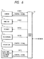
- Fig. 6 is a block diagram showing the schematic arrangement of a conventional TV conference terminal apparatus. Referring to Fig. 6, this apparatus includes a
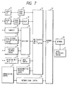
video camera 10 for photographing, e.g., participants in a conference at one station, amonitor 12 for displaying images photographed at this station and/or other stations participating in a conference, aspeaker 14, amicrophone 16, anoperation unit 18 for performing control, e.g., panning, tilting, and zooming, of thecamera 10 at the station and cameras in other stations, switching control of the cameras, and the like, input/output equipment terminals 20 including a keyboard of a computer, a still picture input device, a pointing device for inputting plotting pictures, such as a mouse or digitizer, a sub-monitor for displaying images from other auxiliary equipment, and amain body 22 of the TV conference system. - Fig. 7 shows the detailed arrangement of the
main body 22. Referring to Fig. 7, a video I/F 30 serves to connect thecamera 10 and themonitor 12 to themain body 22. The video I/F 30 has image processing functions of performing screen division, image synthesis, character synthesis, and the like. A video coder/decoder (CODEC) 32 codes a video signal from the video I/F 30 and decodes received coded video information. - A voice I/F 34 serves to connect the
speaker 14 and themicrophone 16 to themain body 22, and has voice processing functions such as an echo cancel function. A voice coder/decoder (CODEC) 36 codes a voice signal from the voice I/F 30 and decodes the received coded voice information. Adelay circuit 38 delays coded voice information obtained by thevoice CODEC 36 and received coded voice information by a predetermined period. Thedelay circuit 38 serves to synchronize voice information to video information. - A
computer 40 provides a TV conference function and a computer conference function. A still picture/plottingpicture control circuit 42 controls the still picture input/output operation and plotting picture input/output operation of the auxiliary input/output equipment terminal 20. Adata port 46 performs data transfer between themain body 22 and the auxiliary input/output equipment terminal 20 via thecomputer 40, the still picture/plottingpicture control circuit 42, and an auxiliaryequipment control circuit 44. - An interconnection
procedure control circuit 48 controls interconnection with other TV conference terminals via a network. A networksignal control circuit 50 performs end/end control to establish a common mode for communications between terminals. Acommunication control circuit 52 performs overall communication control by using the interconnectionprocedure control circuit 48 and the networksignal control circuit 50. - A multiplexing and
demultiplexing circuit 54 performs multiplex transmission of data. A network I/F 56 serves to connect acommunication network 58 to themain body 22. Aninter-multipoints control circuit 60 interconnects TV conference terminals at multiple points to allow a TV conference between the multiple points. An operation unit input I/F 62 receives various commands from the operation unit. Aninput control unit 64 outputs a command to each component of the self station in accordance with a designation of the operation unit input I/F 62. - When a conference is to be held by using a communication conference system such as the TV conference system described above, schedule adjustment between communication terminals must be performed.
- More specifically, the communication terminals negotiate with each other about the date of the conference and the time which can be spared for the conference, thereby performing schedule adjustment. If, however, an international conference is to be held, the working days and hours in each country participating in the conference, time differences, and the like must be considered. In this case, mistakes tend to occur. Especially when terminals belonging to a plurality of countries participate in a conference, communications for schedule adjustment alone cost a great deal.
- It is an object of the present invention to provide a communication terminal apparatus and a communication conference system with improved features.
- European Patent Specification No. EP-A-0349709 discloses a video conference installation which has transmission and reception devices for handling audio and video signals from a plurality of subscriber points. A subscriber can initiate control and carry out switching actions by using position sensitive screen input.
- In one aspect, the present invention aims to provide a communication terminal apparatus and a communication conference system which can easily perform schedule adjustment.
- According to one aspect of the present invention, there is provided a schedule managing apparatus as set out in claim 1.
- In accordance with a second aspect of the present invention there is provided a schedule managing method as set out in claim 13.
- Another aspect of the present invention aims to provide a communication terminal apparatus and a communication conference system in which mistakes are not easily caused in performing communication schedule adjustment.
- Still another aspect of the invention aims to provide a communication terminal apparatus and a communication conference system which can reduce the communication cost required for communication schedule adjustment.
- Other aspects and features of the invention will become apparent from the following detailed description of the embodiments taken in conjunction with the accompanying drawings.
-
- Fig. 1 is a block diagram showing the schematic arrangement of an embodiment of the present invention;
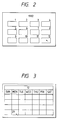
- Fig. 2 is a view showing a displayed state of an yearly calendar according to the embodiment;
- Fig. 3 is a view showing a displayed state of a monthly calendar according to the embodiment;
- Fig. 4 is a view showing a displayed state of a timetable of Japan according to the embodiment;
- Fig. 5 is a view showing a displayed state of a timetable obtained by converting the timetable in accordance with U.S.A.time;
- Fig. 6 is a block diagram showing the schematic arrangement of a conventional system;
- Fig. 7 is a block diagram showing the schematic
arrangement of a
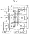
main body 22; - Fig. 8 is a block diagram showing the arrangement
of an inter-multipoints
connection control unit 60 according to the embodiment; and - Fig. 9 is a block diagram showing the overall arrangement of an inter-multipoints connection TV conference system according to the embodiment.
-
- An embodiment of the present invention will be described below with reference to the accompanying drawings.
- Fig. 1 is a block diagram showing the schematic arrangement of a TV conference terminal according to an embodiment of the present invention. The same reference numerals in Fig. 1 denote the same parts as in Fig. 6, and a description thereof will be omitted. Referring to Fig. 1, this terminal includes a
calendar clock 24 and a timedifference conversion circuit 26. Thecalendar clock 24 stores calendar information of the station with which the terminal is associated (hereinafter referred to as "terminal station") and year/month/day/time information in a ROM (not shown). Thecalendar clock 24 has a RAM (not shown) capable of writing and reading the. determined schedule information of a TV conference therein and therefrom, and outputting information, as needed. The timedifference conversion circuit 26 stores the time differences between the home country and other countries, and has a time difference conversion table 27 for converting date information of a partner's country sent from a partner's station into date information of the home country by using the ID information and date information of the partner's country as an address of the table. - Figs. 2, 3, 4, and 5 show examples of how date information is displayed in this embodiment. Characteristic operations of the embodiment will be described below with reference to Figs. 2 to 5.
- When a calendar is required in the process of a conference (e.g., in determining a conference schedule), the calendar is read out from the ROM in the
calendar clock 24 in accordance with a designation from anoperation unit 28 and is displayed on the submonitor of an auxiliary input/output equipment terminal 20. In some case, calendar data of the terminalstation is sent to a partner's station to be displayed on its submonitor. In contrast to this, calendar data of the partner's station may be read out from acalendar clock 24 of the partner's station, received, and displayed on the submonitor of the terminalstation or the partner's station. - Fig. 2 shows an example of display. As shown in Fig. 2, an yearly calendar (1992 calendar in Fig. 2) including the current day is displayed in accordance with a designation from the
operation unit 28. If December is selected by using a pointing device of the auxiliary input/output equipment terminal 20, a monthly calendar of December is displayed. In this case, a monthly calendar of December is also displayed in the partner's station. The displayed contents reflect holidays and public holidays in each country in accordance with the timedifference conversion circuit 26. - Assume that the 29th day is selected on the submonitor in the state shown in Fig. 3 by using the pointing device. In this case, as shown in Fig. 4, the timetable of the 29th day is displayed. If, for example, "9:00 - 11:00 A.M." in Japan is selected, as shown in Fig. 4, ID information indicating the transmission side, i.e., Japan, and year/month/day/time information are sent to the partner's station in accordance with the selection, and the time data is converted into time data corresponding to the country of the partner's station by a time
difference conversion circuit 26 of the partner's station and displayed, as shown in Fig. 5. If, for example, the partner's station is in the eastern part of the U.S.A, "7:00 - 9:00 P.M." on December 28 is displayed. - In addition, date information set before time difference conversion by the time
difference conversion circuit 26 is preferably displayed on the submonitor at the same time. With this operation, the date information of the communication partner in the partner's country can be known on the screen. Therefore, schedule adjustment can be performed by comparing the year/month/day/time information of the communication partner with the year/month/day/time of the self station. Furthermore, a TV conference terminal is shared by a plurality of persons. If, for example, determined schedule information, e.g., the expected date of a conference, is written in the RAM in thecalendar clock 24 in addition to the calendar display, an operator at each station can run through the operation schedule of the TV conference system by displaying the calendar on the submonitor. In addition, the operator can see the conference schedule of each station to prevent overlapping of expected operation times. By displaying expected TV conference system operation information on the partner's station, the schedule of the partner's station can also be checked, thereby facilitating determination of the date of the next conference. In this case, the detailed contents of the schedule can be masked with respect to the partner's station. Furthermore, individual schedule information in the electronic notebook of each user can be written in the RAM in thecalendar clock 24 via an interface (not shown) of the auxiliary input/output equipment terminal 20, and can be displayed on the monitors in the self station and the partner's station. In this case, the schedule information can be transmitted while the detailed contents of the schedule of the terminal station are masked in accordance with the operation of theoperation unit 28. With this operation, schedule adjustment can be performed while the user in the terminal station sees the contents of the schedule on the monitor in the self station, and the communication partner checks the presence/absence of free time in the schedule information received from the self station. Therefore, schedule adjustment can be performed while a change in the schedule is considered in accordance with the contents of the schedule. - In addition, in each station, the desired date of a conference may be temporarily stored in the RAM of the
calendar clock 24. In determining the expected date of the next conference at the end of the conference, desired conference dates may be designated at predetermined portions of a calendar transmitted to the partner's terminal. In this case, the timedifference conversion circuits 26 in the respective stations are designed to collate the desired conference dates with each other so that overlapping desired dates can be automatically and identifiably displayed on the calendars on the submonitors in the respective stations. - Similarly, in each station, the time
difference conversion circuit 26 may have a function of identifiably displaying a day time zone in each country, e.g., from 8:30 A.M. to 6:00 P.M., on the calendar of a partner's station. - In the above embodiment, date information and country ID information are transmitted to a partner's terminal. It is, however, apparent that the country ID information of a communication partner may be identified at the beginning of communication, and date information of the terminal station may be transmitted to the partner's terminal upon conversion of the date information.
- An embodiment in which the above embodiments are applied to an inter-multipoints TV conference system will be described next.
- When a TV conference is to be held upon interconnecting three or more points, a star connection scheme is employed, as shown in Fig. 9. In this case, an inter-multipoints
connection control unit 60 is required. Fig. 8 shows the detailed arrangement of the inter-multipointsconnection control unit 60. - Referring to Fig. 8, multiplexing/
demultiplexing circuits selection control circuit 76 selects data to be distributed from individual stations. Avoice mixer 78 synthesizes voice data from the individual stations. A dataselection control circuit 80 selects and distributes data such as still picture data and computer data. Acontrol circuit 82 controls the imageselection control circuit 76, thevoice mixer 78, and the dataselection control circuit 80. - Network I/
Fs communication control unit 90 controls network access to each station. Similar to Fig. 1, this system includes acalendar clock 24 and a timedifference conversion circuit 26. - In this case, the terminal of each station need not have the
calendar clock 24 and the timedifference conversion circuit 26 and may transmit only ID information indicating the country or area of the self station or a partner's station to the inter-multipointsconnection control unit 60. Thecalendar clock 24 of the inter-multipointsconnection control unit 60 counts only one kind of standard time, e.g., Greenwich mean time. Calendar data is converted by the timedifference conversion circuit 26 on the basis of ID information transmitted from each station, and the calendar data is transmitted thereto. - Pieces of such ID information may be communicated between the respective terminals at the beginning of a conference so that each terminal can recognize the ID information of the partner's terminal. In this case, if a given terminal requests the calendar data of a given country or area, ID information indicating the country or area may be transmitted to the inter-multipoints
connection control unit 60. With this operation, a terminal in each station can extract the calendar data of any country or area from the inter-multipointsconnection control unit 60 in accordance with ID information, regardless of where the corresponding station participates in a conference, and can display the calendar data on a monitor in a station which requests it. If each station includes thecalendar clock 24 and the timedifference conversion circuit 26, each station can cause the inter-multipointsconnection control unit 60 to perform a similar operation, in addition to the above operation. - The above calendar data is calculated by a computer program for producing a calendar in consideration of an arbitrary year, e.g., a leap year. The above time difference data is calculated from Greenwich mean time in each country. Therefore, pieces of information unique to each country or area, e.g., public holidays, holidays, and summer time, may be set in the calendar clock and the time difference conversion circuit in advance for each country.
- As described above, in holding a conference, calendar data is displayed on the monitor in the terminal station in accordance with the operation of the operation unit, while the calendar data is converted in the partner's station in consideration of the time difference, thereby facilitating schedule adjustment and saving a communication time. In addition, calendar data received from the partner's station can be displayed without performing time difference conversion so that each station can perform schedule adjustment while checking local times in the partner's station. Since a given user can perform schedule adjustment upon checking expected conference terminal operation information, the operation schedule of the user does not overlap the operation schedules of other users. In addition, a schedule written in the electronic notebook of each user can be input to the system through the interface, schedule adjustment can be performed in accordance with the priorities of schedules. Since each station can send only scheduled times to the partner's station while masking the detailed contents of the schedule, private information can be protected against the communication partner. Moreover, overlapping desired dates can be automatically and identifiably displayed on the terminals in the respective stations to save communications for schedule adjustment. Although a TV conference system has been described above, it is apparent that the present invention can be applied to any communication terminal system.
Claims (15)
- A communication conference schedule managing apparatus (Fig.1, 60) comprising:receiving means (22) for receiving from a conference station located in a first area first schedule information (Fig.4) represented in the local time of said first area; and characterised bysaid receiving means comprising time difference converting means (26) for converting the first schedule information to second schedule information (Fig.5) represented in the local time of a second area on the basis of the local time difference between the first area and the second area;output means (20) for outputting the second schedule information,
wherein each of the first and second schedule information is utilised to determine the time span from start to end of a predetermined schedule. - Apparatus according to claim 1, wherein said schedule managing apparatus is a terminal set in the second area, and wherein said receiving means receives the first schedule information from a first terminal set in the first area.
- Apparatus according to claim 1, wherein said schedule managing apparatus is a terminal set in the first area, and wherein said output means outputs the second schedule information to a first terminal set in the first area.
- Apparatus according to claim 1, and adapted to relay a communication between a first terminal set in the first area and a second terminal set in the second area.
- Apparatus according to any preceding claim, wherein said output means (20) is adapted to display the second schedule information.
- Apparatus according to claim 1, wherein the first schedule information is schedule information of a user of a terminal set in the first area.
- Apparatus according to any preceding claim, further comprising a video camera for taking an image.
- Apparatus according to any preceding claim, further comprising a speaker for outputting received audio signals.
- Apparatus according to any preceding claim, further comprising a microphone for inputting audio signals for transmission.
- Apparatus according to any preceding claim, wherein said receiving means receives ID information indicating the first area, and wherein said time difference converting means converts the first schedule information to the second schedule information on the basis of the ID information.
- Apparatus according to claim 10, wherein said time difference converting means has a table for outputting the second schedule information as an address for the ID information and the first schedule information.
- A system comprising a communication conference schedule managing apparatus as claimed in claim 4, and a terminal having output means for outputting schedule information relayed to it by said communication conference schedule managing apparatus.
- A method of managing schedules of communication conferences comprising the steps of: receiving first schedule information from a conference station located in a first area, the schedule information representing a schedule in the local time at said first area, said step of receiving utilising a time difference converting step for converting the first schedule information to second schedule information represented in the local time of a second area on the basis of the local time difference between the first area and the second area; outputting the second schedule information, and utilising the first and second schedule information to determine the time span from start to end of a predetermined schedule.
- A method according to claim 13, wherein the first and second schedule information is received at a schedule managing apparatus and is output to at least one other terminal.
- A method according to claim 14, wherein the first and second schedule information is received from differing video conferencing terminals and is sent to a third video conferencing terminal.
Applications Claiming Priority (6)
| Application Number | Priority Date | Filing Date | Title |
|---|---|---|---|
| JP21437493 | 1993-08-30 | ||
| JP21437493 | 1993-08-30 | ||
| JP214374/93 | 1993-08-30 | ||
| JP19834494 | 1994-08-23 | ||
| JP6198344A JPH07123167A (en) | 1993-08-30 | 1994-08-23 | Communication terminal equipment and communication conference system |
| JP198344/94 | 1994-08-23 |
Publications (2)
| Publication Number | Publication Date |
|---|---|
| EP0641129A1 EP0641129A1 (en) | 1995-03-01 |
| EP0641129B1 true EP0641129B1 (en) | 2000-06-28 |
Family
ID=26510927
Family Applications (1)
| Application Number | Title | Priority Date | Filing Date |
|---|---|---|---|
| EP94306329A Expired - Lifetime EP0641129B1 (en) | 1993-08-30 | 1994-08-26 | Communication conference schedules managing apparatus and method |
Country Status (4)
| Country | Link |
|---|---|
| US (1) | US6205089B1 (en) |
| EP (1) | EP0641129B1 (en) |
| JP (1) | JPH07123167A (en) |
| DE (1) | DE69425027T2 (en) |
Families Citing this family (14)
| Publication number | Priority date | Publication date | Assignee | Title |
|---|---|---|---|---|
| US6525761B2 (en) | 1996-07-23 | 2003-02-25 | Canon Kabushiki Kaisha | Apparatus and method for controlling a camera connected to a network |
| US7249061B1 (en) * | 1997-03-14 | 2007-07-24 | Kabushiki Kaisha Toshiba | Method of electronic commerce including receiving an acceptance signal indicating a change in a transaction available period based on a time adjustment day |
| US6064975A (en) * | 1997-10-22 | 2000-05-16 | Ericsson Inc. | Apparatus and method for highlighting holidays of a specified location in a calendar software application |
| EP1025526A1 (en) * | 1997-10-24 | 2000-08-09 | Microsoft Corporation | Generating meeting requests and group scheduling from a mobile device |
| JP3986687B2 (en) * | 1998-09-18 | 2007-10-03 | 株式会社リコー | Facsimile device |
| JPWO2002027583A1 (en) * | 2000-09-27 | 2004-02-05 | 株式会社東芝 | Electronic commerce server, electronic commerce method, and recording medium recording electronic commerce program |
| KR100452819B1 (en) | 2002-03-18 | 2004-10-15 | 삼성전기주식회사 | Chip scale package and method of fabricating the same |
| JP2005352933A (en) * | 2004-06-14 | 2005-12-22 | Fuji Xerox Co Ltd | Display arrangement, system, and display method |
| US7856483B2 (en) | 2004-12-10 | 2010-12-21 | Microsoft Corporation | Information management systems with time zone information, including event scheduling processes |
| US8626556B2 (en) * | 2005-04-25 | 2014-01-07 | International Business Machines Corporation | Visualizing multiple time zones in a calendaring and scheduling application |
| JP4564410B2 (en) * | 2005-06-16 | 2010-10-20 | オリンパスイメージング株式会社 | Image playback device |
| US7813325B2 (en) * | 2006-03-03 | 2010-10-12 | Sony Ericsson Mobile Communications Ab | Location information communication |
| US20090077819A1 (en) * | 2007-09-21 | 2009-03-26 | Black & Decker Inc. | Cutting Angle Indicator in Jigsaw Housing with Positive Lock in Separately Assembled Shoe Sub-Assembly |
| JP2009086850A (en) * | 2007-09-28 | 2009-04-23 | Hitachi Ltd | Schedule management system |
Family Cites Families (14)
| Publication number | Priority date | Publication date | Assignee | Title |
|---|---|---|---|---|
| US4977529A (en) * | 1973-02-23 | 1990-12-11 | Westinghouse Electric Corp. | Training simulator for a nuclear power plant |
| US4725886A (en) * | 1983-04-21 | 1988-02-16 | The Weather Channel, Inc. | Communications system having an addressable receiver |
| US4831552A (en) * | 1987-01-29 | 1989-05-16 | International Business Machines Corporation | Method for concurrently displaying entries from a plurality of different electronic calendars based on interactively entered non-temporal criteria |
| US4774658A (en) * | 1987-02-12 | 1988-09-27 | Thomas Lewin | Standardized alarm notification transmission alternative system |
| US4987492A (en) * | 1987-09-28 | 1991-01-22 | Stults Robert A | User interface control for communication system |
| DE3823219C1 (en) | 1988-07-08 | 1989-05-18 | Telenorma Telefonbau Und Normalzeit Gmbh, 6000 Frankfurt, De | |
| US4882743A (en) * | 1988-08-01 | 1989-11-21 | American Telephone And Telegraph | Multi-location video conference system |
| US5375018A (en) * | 1990-07-18 | 1994-12-20 | Klausner Patent Technologies | Location acquisition and time adjusting system |
| US5062136A (en) * | 1990-09-12 | 1991-10-29 | The United States Of America As Represented By The Secretary Of The Navy | Telecommunications system and method |
| EP0836323B1 (en) * | 1991-02-20 | 2004-01-14 | Hitachi, Ltd. | Television telephone |
| DE4140017C2 (en) * | 1991-12-04 | 1995-01-05 | Nec Electronics Germany | Method for operating computer units communicating with one another via a data bus by serial data exchange |
| SG46597A1 (en) * | 1992-03-26 | 1998-02-20 | Nec Corp | Mobile terminal equipment |
| JPH06225301A (en) * | 1993-01-25 | 1994-08-12 | Matsushita Electric Ind Co Ltd | Communication terminal equipment |
| US5455807A (en) * | 1993-08-18 | 1995-10-03 | Seiko Corp. | Time maintenance and display in a time keeping system including a time zone boundary |
-
1994
- 1994-08-23 JP JP6198344A patent/JPH07123167A/en not_active Withdrawn
- 1994-08-26 DE DE69425027T patent/DE69425027T2/en not_active Expired - Lifetime
- 1994-08-26 EP EP94306329A patent/EP0641129B1/en not_active Expired - Lifetime
- 1994-08-29 US US08/297,180 patent/US6205089B1/en not_active Expired - Lifetime
Also Published As
| Publication number | Publication date |
|---|---|
| DE69425027D1 (en) | 2000-08-03 |
| EP0641129A1 (en) | 1995-03-01 |
| JPH07123167A (en) | 1995-05-12 |
| US6205089B1 (en) | 2001-03-20 |
| DE69425027T2 (en) | 2001-02-22 |
Similar Documents
| Publication | Publication Date | Title |
|---|---|---|
| EP0641129B1 (en) | Communication conference schedules managing apparatus and method | |
| JP3319618B2 (en) | Video conference system | |
| EP0571119B1 (en) | Video services | |
| CA2073925C (en) | Multipoint teleconference system employing h.221 frames | |
| JP3305037B2 (en) | Multipoint control device, video conference terminal device, and multipoint video conference system | |
| KR0163723B1 (en) | Apparatus of controlling a video conferencing of a video conferencing system using isdn | |
| US5444477A (en) | Video telephone system | |
| KR100210546B1 (en) | Television conferencing system | |
| AU2001215578B2 (en) | Teleconferencing system | |
| US6621514B1 (en) | Video conferencing system | |
| JPH05347674A (en) | Synchronization displaty controller | |
| US5774457A (en) | Multi-point video conference control apparatus | |
| KR100203279B1 (en) | The multi-point control unit of video conference that has terminal information | |
| JP3123685B2 (en) | Group video communication system | |
| JP3258409B2 (en) | Teleconference equipment | |
| JPH07131771A (en) | Video conference system | |
| JP2707948B2 (en) | Multipoint TV lecture system | |
| JP3787568B2 (en) | Display control apparatus and display control method | |
| JP3107465B2 (en) | Video conference system | |
| JP3308905B2 (en) | Video conference terminal | |
| JP3491932B2 (en) | Video conference system | |
| KR970007009B1 (en) | Real-time visual conference system | |
| JP3124646B2 (en) | Multimedia transmission system and method | |
| JPH0435591A (en) | Video conference equipment | |
| US20030101221A1 (en) | Network conference system and method for using the same |
Legal Events
| Date | Code | Title | Description |
|---|---|---|---|
| PUAI | Public reference made under article 153(3) epc to a published international application that has entered the european phase |
Free format text: ORIGINAL CODE: 0009012 |
|
| AK | Designated contracting states |
Kind code of ref document: A1 Designated state(s): DE FR GB |
|
| 17P | Request for examination filed |
Effective date: 19950713 |
|
| 17Q | First examination report despatched |
Effective date: 19980309 |
|
| GRAG | Despatch of communication of intention to grant |
Free format text: ORIGINAL CODE: EPIDOS AGRA |
|
| RTI1 | Title (correction) |
Free format text: COMMUNICATION CONFERENCE SCHEDULES MANAGING APPARATUS AND METHOD |
|
| GRAG | Despatch of communication of intention to grant |
Free format text: ORIGINAL CODE: EPIDOS AGRA |
|
| GRAH | Despatch of communication of intention to grant a patent |
Free format text: ORIGINAL CODE: EPIDOS IGRA |
|
| GRAH | Despatch of communication of intention to grant a patent |
Free format text: ORIGINAL CODE: EPIDOS IGRA |
|
| GRAA | (expected) grant |
Free format text: ORIGINAL CODE: 0009210 |
|
| AK | Designated contracting states |
Kind code of ref document: B1 Designated state(s): DE FR GB |
|
| REF | Corresponds to: |
Ref document number: 69425027 Country of ref document: DE Date of ref document: 20000803 |
|
| ET | Fr: translation filed | ||
| PLBE | No opposition filed within time limit |
Free format text: ORIGINAL CODE: 0009261 |
|
| STAA | Information on the status of an ep patent application or granted ep patent |
Free format text: STATUS: NO OPPOSITION FILED WITHIN TIME LIMIT |
|
| 26N | No opposition filed | ||
| REG | Reference to a national code |
Ref country code: GB Ref legal event code: IF02 |
|
| PGFP | Annual fee paid to national office [announced via postgrant information from national office to epo] |
Ref country code: DE Payment date: 20130831 Year of fee payment: 20 |
|
| PGFP | Annual fee paid to national office [announced via postgrant information from national office to epo] |
Ref country code: FR Payment date: 20130823 Year of fee payment: 20 Ref country code: GB Payment date: 20130822 Year of fee payment: 20 |
|
| REG | Reference to a national code |
Ref country code: DE Ref legal event code: R071 Ref document number: 69425027 Country of ref document: DE |
|
| REG | Reference to a national code |
Ref country code: GB Ref legal event code: PE20 Expiry date: 20140825 |
|
| PG25 | Lapsed in a contracting state [announced via postgrant information from national office to epo] |
Ref country code: DE Free format text: LAPSE BECAUSE OF EXPIRATION OF PROTECTION Effective date: 20140827 |
|
| PG25 | Lapsed in a contracting state [announced via postgrant information from national office to epo] |
Ref country code: GB Free format text: LAPSE BECAUSE OF EXPIRATION OF PROTECTION Effective date: 20140825 |