EP0640926A1 - Priority encoder - Google Patents
Priority encoder Download PDFInfo
- Publication number
- EP0640926A1 EP0640926A1 EP94410068A EP94410068A EP0640926A1 EP 0640926 A1 EP0640926 A1 EP 0640926A1 EP 94410068 A EP94410068 A EP 94410068A EP 94410068 A EP94410068 A EP 94410068A EP 0640926 A1 EP0640926 A1 EP 0640926A1
- Authority
- EP
- European Patent Office
- Prior art keywords
- mask
- request
- bits
- encoder
- rank
- Prior art date
- Legal status (The legal status is an assumption and is not a legal conclusion. Google has not performed a legal analysis and makes no representation as to the accuracy of the status listed.)
- Granted
Links
Images

Classifications
-
- G—PHYSICS
- G06—COMPUTING; CALCULATING OR COUNTING
- G06F—ELECTRIC DIGITAL DATA PROCESSING
- G06F13/00—Interconnection of, or transfer of information or other signals between, memories, input/output devices or central processing units
- G06F13/14—Handling requests for interconnection or transfer
- G06F13/36—Handling requests for interconnection or transfer for access to common bus or bus system
- G06F13/362—Handling requests for interconnection or transfer for access to common bus or bus system with centralised access control
- G06F13/364—Handling requests for interconnection or transfer for access to common bus or bus system with centralised access control using independent requests or grants, e.g. using separated request and grant lines
-
- G—PHYSICS
- G06—COMPUTING; CALCULATING OR COUNTING
- G06F—ELECTRIC DIGITAL DATA PROCESSING
- G06F13/00—Interconnection of, or transfer of information or other signals between, memories, input/output devices or central processing units
- G06F13/14—Handling requests for interconnection or transfer
- G06F13/20—Handling requests for interconnection or transfer for access to input/output bus
- G06F13/24—Handling requests for interconnection or transfer for access to input/output bus using interrupt
- G06F13/26—Handling requests for interconnection or transfer for access to input/output bus using interrupt with priority control
Definitions
- the present invention relates to a priority level coder which is a circuit serving to acknowledge the highest priority request among a set of requests arriving in the form of active signals at the coder. Acknowledging a request consists in validating a circuit (often a microprocessor) so that the latter performs the task corresponding to the request.
- a priority level coder receives one or more simultaneous requests on a set of assigned request lines of respective ranks, for example from 1 to n, and acknowledges only one request at a time by acknowledgment lines.
- the acknowledgment lines correspond directly to the request lines and the encoder transmits on the acknowledgment lines only the only acknowledged request.
- the acknowledgment lines provide, in binary form, the rank of the acknowledged request.
- the priorities assigned to the request lines are distinct, the priorities being for example assigned in decreasing order to the ranks of the request lines.
- the linear coder always acknowledges the request for the lowest rank, and a request for a given rank is not acknowledged as long as there are requests for lower rank.
- a linear encoder is conventionally made up of a non-sequential logic circuit, of the carry propagation type, which acknowledges the request for the lowest rank shortly (depending on the carry propagation delay) after any change in the states query lines.
- the request lines are assigned the same priority level.
- Such an encoder must guarantee, if several requests are active at the same time, that each of these requests is acknowledged at a given time.
- a conventional circular encoder consists of a sequential logic circuit which performs a circular scanning of the request lines at the rate of a clock. At each clock cycle, the sequential circuit scans a request line. If the scanned request line is active, the corresponding acknowledgment is sent, and the scanning of the request lines continues from the last scanned line. When the request row of last rank, n, is scanned, the scanning starts again on the request row of rank 1 ...
- a disadvantage of the above-mentioned circular encoder is that it only processes one request line per clock cycle. In other words, if the circuit has just scanned the row of rank i and the next active request is of rank j (j> i), the request of rank j is only acknowledged after j-i clock cycles afterwards.
- An object of the present invention is to provide a circular priority level encoder enabling requests of any rank to be acknowledged at successive clock cycles.
- Another object of the present invention is to provide an encoder of mixed priority level making it possible, in a programmable manner, to treat part of the requests as requests of distinct priorities (linear coding) and another part of the requests as requests. of identical priority (circular coding), and this while acknowledging a request at each clock cycle.
- the masking register comprises an initialization input activated when the acknowledgment output of the linear encoder is at zero.
- the invention also provides a mixed priority level encoder further comprising means for forcing an active state of the selected bits of the masks supplied by the mask generator.
- the coder comprises means for authorizing the loading of a mask into the masking register only if the acknowledged request corresponds to the bits not forced to an active state of the masks.
- a circular priority level coder comprises a linear priority level coder (LINP) 10.
- This linear coder receives request lines from ranks 1 to n via a register masking (MASK REG) 12.
- RQ register masking
- RQM register masking
- the acknowledgment output ACK of the linear encoder 10 is connected to a mask generator (MGEN) 14 which supplies a mask M to the masking register 12, which is a function of the rank of the request acknowledged by the linear encoder 10.
- a mask M supplied by the generator 14 comprises a bit associated with each request line RQ.
- the masking register 12 is such that an active state of a request line RQ is transmitted to the linear encoder 10 only if the corresponding bit of the mask is active, for example at 1.
- the masking register 12 receives a clock signal CK which causes, on each rising edge for example, the storage of the states of the request lines RQ and of the mask M supplied by the mask generator 14.
- the masking register includes an entry for "asynchronous S" (ie which, as soon as it is activated, sets the mask contained in the masking register to 1).
- This setting input to 1 is validated when the linear encoder 10 has no request to be acknowledged, that is to say when its ACK output is at 0.
- the ACK output is supplied to a NOR gate 16 the output of which is supplied to the input to 1S of the masking register 12.
- the mask generator 14 is such that it provides a mask whose bits of ranks 1 to i are at 0 and the remaining bits at 1 when the linear coder 10 acknowledges the request of rank i.
- Such a mask generator can be easily produced by a person skilled in the art using logic gates.
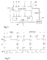
- FIG. 2 illustrates, using a timing diagram, the operation of the circular encoder according to the invention.
- This figure represents the shape of the clock signal CK, the masks M loaded in the masking register 12 and the acknowledgment ACK of various requests.
- Instants t1 to t4 designate successive rising edges of the clock CK and instants t1 'to t3' designate the falling edges.
- an initial mask is loaded into the masking register 12, all the bits of which are at 1, and the states of the request lines RQ are stored in this register.
- the linear encoder 10 does not acknowledge any request, its ACK output is at 0. All the requests on the lines RQ are transmitted to the linear encoder 10. It is assumed that only the row of rank i is active. Some time after the instant t1, for example in the vicinity of the instant t1 'at the falling edge of the clock CK, the linear coder 10 acknowledges the request i. As soon as this acknowledgment is made, the mask generator 14 establishes a mask M whose bits of ranks 1 to i are at 0 and the other bits at 1.
- the aforementioned mask established by the mask generator 14 is loaded into the masking register 12 and the states of the request lines RQ are stored.
- the lines RQ present new requests of ranks j and k (j ⁇ k) lower than rank i.
- these requests of rank j and k are masked; the linear encoder 10 receives no request.
- the linear encoder 10 supplies the value 0 on its acknowledgment output ACK.
- the masking register is set to 1 by gate 16, this which then causes the transmission of requests of rank j and k to the linear encoder 10.
- the linear encoder 10 acknowledges the request of rank j, rank j being less than rank k.
- the mask generator 14 then establishes a mask M whose bits of rank 1 to j are at 0 and the other bits at 1.
- this new mask is loaded into the masking register 12 and the new requests on the lines RQ are stored.
- the requests of rank j and k are always active. However, the request for rank j is now masked and does not reach the linear encoder 10. Only the request for rank k is transmitted to the encoder 10 which acknowledges this request in the vicinity of an instant t3 '. Upon this acknowledgment, the mask generator 14 establishes a new mask M, the bits of rank 1 to k are at 0 and the other bits to 1 ...
- the timing diagram of FIG. 2 shows that the circuit of FIG. 1 operates as a circular priority level coder which has the advantage of fulfilling an active request at each clock cycle.
- FIG. 3 shows an embodiment of a mixed priority level coder according to the present invention.
- This encoder is used to process low ranking requests as as separate priority requests (linear coding), and high ranking requests as identical priority requests (circular coding).
- linear coding linear coding
- high ranking requests identical priority requests
- a set of OR gates 18 has been added, each receiving a bit of a register (REG) 20 and a bit of a mask M1 supplied by the mask generator 14.
- the outputs of the gates OR 18 provide the mask M to the masking register 12.
- register 20 is write-accessible by the microprocessor, which makes it possible to write values to this register by program.
- the requests of rank 1 to i of the register 20 are always transmitted to the linear encoder 10.
- the requests of rank 1 to i are permanently processed so classical linear by the linear encoder 10, as requests for distinct priorities.
- the mask generator 14 operating as previously described, the remaining requests, of rows i + l to n, are processed in a circular manner.
- the linear coder 10 acknowledges the highest priority among these active requests.
- the mask generator 14 supplies each of these acknowledgments with a mask whose first bits are at 0 but which are forced to 1 by the OR gates 18.
- the circuit behaves like the circuit of FIG. 1, that is to say in a circular manner, for requests of rank higher than i.
- FIG. 4 represents an example of a logic circuit added to the circuit of FIG. 3, which allows the mixed coder according to the invention to process the requests in a circular or linear manner according to any combinations determined by the register 20.
- Each ACK acknowledgment line is connected to a first input of a respective AND gate 40.
- Each L / C line of output from register 20 is connected to a second, inverting input of the corresponding AND gate 40.
- the outputs of the doors 40 are connected to an OR gate 42.
- the output of gate 42 is active only when a circular priority request is acknowledged.
- the output of this gate 42 validates the transmission of the clock signal CK to the masking register 12 by means of an AND gate 44. Consequently, a new mask M is loaded into the masking register 12 only if a request for circular priority is acknowledged.
Abstract
Description
La présente invention concerne un codeur de niveau de priorité qui est un circuit servant à acquitter la requête la plus prioritaire parmi un ensemble de requêtes arrivant sous forme de signaux actifs au codeur. L'acquittement d'une requête consiste à valider un circuit (souvent un microprocesseur) pour que ce dernier effectue la tâche correspondant à la requête.The present invention relates to a priority level coder which is a circuit serving to acknowledge the highest priority request among a set of requests arriving in the form of active signals at the coder. Acknowledging a request consists in validating a circuit (often a microprocessor) so that the latter performs the task corresponding to the request.
Un codeur de niveau de priorité reçoit une ou plusieurs requêtes simultanées sur un ensemble de lignes de requête affectées de rangs respectifs, par exemple de 1 à n, et acquitte une seule requête à la fois par des lignes d'acquittement. Dans certains codeurs, les lignes d'acquittement correspondent directement aux lignes de requête et le codeur ne transmet sur les lignes d'acquittement que la seule requête acquittée. Dans d'autres codeurs, les lignes d'acquittement fournissent, sous forme binaire, le rang de la requête acquittée.A priority level coder receives one or more simultaneous requests on a set of assigned request lines of respective ranks, for example from 1 to n, and acknowledges only one request at a time by acknowledgment lines. In some encoders, the acknowledgment lines correspond directly to the request lines and the encoder transmits on the acknowledgment lines only the only acknowledged request. In other coders, the acknowledgment lines provide, in binary form, the rank of the acknowledged request.
Il existe actuellement deux types de codeurs de niveau de priorité, l'un dit codeur linéaire et l'autre codeur circulaire.There are currently two types of priority level encoders, one called a linear encoder and the other a circular encoder.
Dans un codeur linéaire, les priorités affectées aux lignes de requête sont distinctes, les priorités étant par exemple affectées par ordre décroissant aux rangs des lignes de requête. Le codeur linéaire acquitte toujours la requête de rang le plus faible, et une requête de rang donné n'est pas acquittée tant qu'il subsiste des requêtes de rang inférieur.In a linear coder, the priorities assigned to the request lines are distinct, the priorities being for example assigned in decreasing order to the ranks of the request lines. The linear coder always acknowledges the request for the lowest rank, and a request for a given rank is not acknowledged as long as there are requests for lower rank.
Un codeur linéaire est classiquement constitué d'un circuit logique non-séquentiel, du type à propagation de retenue, qui acquitte la requête de rang le plus faible peu de temps (dépendant du délai de propagation de la retenue) après un changement quelconque des états des lignes de requête.A linear encoder is conventionally made up of a non-sequential logic circuit, of the carry propagation type, which acknowledges the request for the lowest rank shortly (depending on the carry propagation delay) after any change in the states query lines.
Dans un codeur circulaire, les lignes de requête sont affectées d'un même niveau de priorité. Un tel codeur doit garantir, si plusieurs requêtes sont actives en même temps, que chacune de ces requêtes soit acquittée à un moment donné.In a circular encoder, the request lines are assigned the same priority level. Such an encoder must guarantee, if several requests are active at the same time, that each of these requests is acknowledged at a given time.
Pour cela, un codeur circulaire classique est constitué d'un circuit logique séquentiel qui effectue une scrutation circulaire des lignes de requête à la cadence d'une horloge. A chaque cycle d'horloge, le circuit séquentiel scrute une ligne de requête. Si la ligne de requête scrutée est active, l'acquittement correspondant est envoyé, et la scrutation des lignes de requête se poursuit à partir de la dernière ligne scrutée. Lorsque la ligne de requête de dernier rang, n, est scrutée, la scrutation recommence à la ligne de requête de rang 1...For this, a conventional circular encoder consists of a sequential logic circuit which performs a circular scanning of the request lines at the rate of a clock. At each clock cycle, the sequential circuit scans a request line. If the scanned request line is active, the corresponding acknowledgment is sent, and the scanning of the request lines continues from the last scanned line. When the request row of last rank, n, is scanned, the scanning starts again on the request row of
Ainsi, un inconvénient du codeur circulaire susmentionné, est qu'il ne traite qu'une ligne de requête par cycle d'horloge. En d'autres termes, si le circuit vient de scruter la ligne de rang i et que la requête active suivante est de rang j (j>i), la requête de rang j n'est acquittée que j-i cycles d'horloge après.Thus, a disadvantage of the above-mentioned circular encoder is that it only processes one request line per clock cycle. In other words, if the circuit has just scanned the row of rank i and the next active request is of rank j (j> i), the request of rank j is only acknowledged after j-i clock cycles afterwards.
Un objet de la présente invention est de prévoir un codeur de niveau de priorité circulaire permettant d'acquitter des requêtes de rangs quelconques à des cycles d'horloge successifs.An object of the present invention is to provide a circular priority level encoder enabling requests of any rank to be acknowledged at successive clock cycles.
Un autre objet de la présente invention est de prévoir un codeur de niveau de priorité mixte permettant, de façon programmable, de traiter une partie des requêtes en tant que requêtes de priorités distinctes (codage linéaire) et une autre partie des requêtes en tant que requêtes de priorité identique (codage circulaire), et ceci tout en acquittant une requête à chaque cycle d'horloge.Another object of the present invention is to provide an encoder of mixed priority level making it possible, in a programmable manner, to treat part of the requests as requests of distinct priorities (linear coding) and another part of the requests as requests. of identical priority (circular coding), and this while acknowledging a request at each clock cycle.
Ces objets sont atteints grâce à un codeur de niveau de priorité circulaire comprenant : un codeur de niveau de priorité linéaire recevant une pluralité de requêtes de rangs 1 à n sur des lignes de requête correspondantes, et acquittant sur une sortie d'acquittement la requête de rang le plus faible parmi les requêtes qui lui parviennent ; un registre de masquage connecté pour ne transmettre au codeur linéaire que les requêtes dont les rangs sont déterminés par les rangs de bits actifs d'un masque contenu dans le registre de masquage ; et un circuit de génération de masque fournissant au registre de masquage un masque dont les bits de rang 1 à i (i = 1, 2... n) sont inactifs et les autres bits actifs lorsqu'une requête de rang i est acquittée par le codeur linéaire.These objects are achieved by means of a circular priority level encoder comprising: a linear priority level encoder receiving a plurality of requests from
Selon un mode de réalisation de la présente invention, le registre de masquage comprend une entrée d'initialisation activée lorque la sortie d'acquittement du codeur linéaire est à zéro.According to an embodiment of the present invention, the masking register comprises an initialization input activated when the acknowledgment output of the linear encoder is at zero.
L'invention prévoit également un codeur de niveau de priorité mixte comprenant en outre des moyens pour forcer à un état actif des bits choisis des masques fournis par le générateur de masque.The invention also provides a mixed priority level encoder further comprising means for forcing an active state of the selected bits of the masks supplied by the mask generator.
Selon un mode de réalisation de la présente invention, le codeur comprend des moyens pour n'autoriser le chargement d'un masque dans le registre de masquage que si la requête acquittée correspond aux bits non forcés à un état actif des masques.According to an embodiment of the present invention, the coder comprises means for authorizing the loading of a mask into the masking register only if the acknowledged request corresponds to the bits not forced to an active state of the masks.
Ces objets, caractéristiques et avantages ainsi que d'autres de la présente invention seront exposés en détail dans la description suivante de modes de réalisation particuliers faite en relation avec les figures jointes parmi lesquelles :
- la figure 1 représente un mode de réalisation de codeur de niveau de priorité circulaire selon la présente invention ;
- la figure 2 illustre, à l'aide d'un chronogramme, le fonctionnement du codeur de la figure 1 ;
- la figure 3 représente un mode de réalisation de codeur de niveau de priorité mixte selon la présente invention ; et
- la figure 4 représente une variante du codeur de niveau de priorité mixte de la figure 3.
- FIG. 1 shows an embodiment of a circular priority level coder according to the present invention;
- Figure 2 illustrates, using a timing diagram, the operation of the encoder of Figure 1;
- FIG. 3 shows an embodiment of a mixed priority level coder according to the present invention; and
- FIG. 4 represents a variant of the mixed priority level coder of FIG. 3.
A la figure 1, un codeur de niveau de priorité circulaire selon l'invention comprend un codeur de niveau de priorité linéaire (LINP) 10. Ce codeur linéaire reçoit des lignes de requête de rangs 1 à n par l'intermédiaire d'un registre de masquage (MASK REG) 12. Les lignes de requête reliées à l'entrée du registre de masquage sont notées RQ, et celles reliées entre le registre de masquage et le codeur linéaire 10 sont notées RQM. La sortie d'acquittement ACK du codeur linéaire 10 est reliée à un générateur de masque (MGEN) 14 qui fournit un masque M au registre de masquage 12, qui est fonction du rang de la requête acquittée par le codeur linéaire 10.In FIG. 1, a circular priority level coder according to the invention comprises a linear priority level coder (LINP) 10. This linear coder receives request lines from
Un masque M fourni par le générateur 14 comprend un bit associé à chaque ligne de requête RQ. Le registre de masquage 12 est tel qu'un état actif d'une ligne de requête RQ n'est transmis vers le codeur linéaire 10 que si le bit correspondant du masque est actif, par exemple à 1.A mask M supplied by the
En outre, le registre de masquage 12 reçoit un signal d'horloge CK qui entraîne, à chaque front montant par exemple, la mémorisation des états des lignes de requête RQ et du masque M fourni par le générateur de masque 14. Le registre de masquage comprend une entrée de "mise à un" S asynchrone (c'est-à-dire qui, dès qu'elle est activée, met à 1 le masque contenu dans le registre de masquage). Cette entrée de mise à 1 est validée lorsque le codeur linéaire 10 n'a aucune requête à acquitter, c'est-à-dire lorsque sa sortie ACK est à 0. En pratique, la sortie ACK est fournie à une porte NON OU 16 dont la sortie est fournie à l'entrée de mise à 1 S du registre de masquage 12.In addition, the
Le générateur de masque 14 est tel qu'il fournit un masque dont les bits de rangs 1 à i sont à 0 et les bits restants à 1 lorsque le codeur linéaire 10 acquitte la requête de rang i. Un tel générateur de masque peut être facilement réalisé par l'homme du métier à l'aide de portes logiques.The
La figure 2 illustre, à l'aide d'un chronogramme, le fonctionnement du codeur circulaire selon l'invention. Cette figure représente l'allure du signal d'horloge CK, des masques M chargés dans le registre de masquage 12 et l'acquittement ACK de diverses requêtes. Des instants t1 à t4 désignent des fronts montants successifs de l'horloge CK et des instants t1' à t3' désignent les fronts descendants.FIG. 2 illustrates, using a timing diagram, the operation of the circular encoder according to the invention. This figure represents the shape of the clock signal CK, the masks M loaded in the
A l'instant t1, on charge dans le registre de masquage 12 un masque initial dont tous les bits sont à 1, et les états des lignes de requête RQ sont mémorisés dans ce registre. Le codeur linéaire 10 n'acquitte aucune requête, sa sortie ACK est à 0. Toutes les requêtes sur les lignes RQ sont transmises au codeur linéaire 10. On suppose que seule la ligne de rang i est active. Quelque temps après l'instant t1, par exemple au voisinage de l'instant t1' au front descendant de l'horloge CK, le codeur linéaire 10 acquitte la requête i. Dès cet acquittement, le générateur de masque 14 établit un masque M dont les bits de rangs 1 à i sont à 0 et les autres bits à 1.At time t1, an initial mask is loaded into the
A l'instant t2, le masque susmentionné établi par le générateur de masque 14 est chargé dans le registre de masquage 12 et les états des lignes de requête RQ sont mémorisés. Comme cela est indiqué sur le chronogramme de la figure 2, les lignes RQ présentent des nouvelles requêtes de rangs j et k (j<k) inférieurs au rang i. Toutefois, grâce au masque qui vient d'être chargé à l'instant t2, ces requêtes de rang j et k sont masquées ; le codeur linéaire 10 ne reçoit aucune requête. Au voisinage de l'instant t2', le codeur linéaire 10 fournit sur sa sortie d'acquittement ACK la valeur 0. Dès que la sortie d'acquittement passe à 0, le registre de masquage est mis à 1 par la porte 16, ce qui entraîne alors la transmission des requêtes de rang j et k vers le codeur linéaire 10. Ainsi, quelque temps après le passage à 0 de la sortie d'acquittement ACK, le codeur linéaire 10 acquitte la requête de rang j, le rang j étant inférieur au rang k. Le générateur de masque 14 établit alors un masque M dont les bits de rang 1 à j sont à 0 et les autres bits à 1.At time t2, the aforementioned mask established by the
A l'instant t3, ce nouveau masque est chargé dans le registre de masquage 12 et les nouvelles requêtes sur les lignes RQ sont mémorisées. Les requêtes de rang j et k sont toujours actives. Toutefois, la requête de rang j est maintenant masquée et ne parvient pas au codeur linéaire 10. Seulement la requête de rang k est transmise au codeur 10 qui acquitte cette requête au voisinage d'un instant t3'. Dès cet acquittement, le générateur de masque 14 établit un nouveau masque M dont les bits de rang 1 à k sont à 0 et les autres bits à 1...At time t3, this new mask is loaded into the
Le chronogramme de la figure 2 montre que le circuit de la figure 1 fonctionne en tant que codeur de niveau de priorité circulaire qui présente l'avantage d'acquitter une requête active à chaque cycle d'horloge.The timing diagram of FIG. 2 shows that the circuit of FIG. 1 operates as a circular priority level coder which has the advantage of fulfilling an active request at each clock cycle.
Les acquittements sont généralement pris en compte par d'autres circuits aux fronts montants de l'horloge CK. Ainsi, le passage à 0 de la sortie ACK entre les instants t2' et t3 est ignoré.Acknowledgments are generally taken into account by other circuits at the rising edges of the clock CK. Thus, the passage to 0 of the output ACK between the instants t2 'and t3 is ignored.
La figure 3 représente un mode de réalisation de codeur de niveau de priorité mixte selon la présente invention. Ce codeur permet de traiter les requêtes de rang faible en tant que requêtes de priorités distinctes (codage linéaire), et les requêtes de rang fort en tant que requêtes de priorité identique (codage circulaire). Dans cette figure, des mêmes éléments qu'à la figure 1 sont désignés par des mêmes références.FIG. 3 shows an embodiment of a mixed priority level coder according to the present invention. This encoder is used to process low ranking requests as as separate priority requests (linear coding), and high ranking requests as identical priority requests (circular coding). In this figure, the same elements as in Figure 1 are designated by the same references.
Par rapport au circuit de la figure 1, on a ajouté un ensemble de portes OU 18 recevant chacune un bit d'un registre (REG) 20 et un bit d'un masque M1 fourni par le générateur de masque 14. Les sorties des portes OU 18 fournissent le masque M au registre de masquage 12. Avec cette configuration, si un bit du registre 20 est à 1, le bit correspondant du masque M est toujours à 1, quel que soit le masque M1 fourni par le générateur de masque 14.With respect to the circuit of FIG. 1, a set of OR
Un codeur de niveau de priorité étant généralement associé à un microprocesseur, on peut envisager que le registre 20 soit accessible en écriture par le microprocesseur, ce qui permet d'écrire des valeurs dans ce registre par programme.Since a priority level coder is generally associated with a microprocessor, it can be envisaged that register 20 is write-accessible by the microprocessor, which makes it possible to write values to this register by program.
Si l'on suppose que les bits de rang 1 à i du registre 20 sont à 1, les requêtes de rang 1 à i sont toujours transmises au codeur linéaire 10. Ainsi, les requêtes de rang 1 à i sont en permanence traitées de manière linéaire classique par le codeur linéaire 10, en tant que requêtes de priorités distinctes. Par contre, le générateur de masque 14 fonctionnant comme cela a été précédemment décrit, les requêtes restantes, de rangs i+l à n, sont traitées de manière circulaire.If it is assumed that the bits of
En effet, tant qu'une requête de rang 1 à i est active, le codeur linéaire 10 acquitte la plus prioritaire parmi ces requêtes actives. Le générateur de masque 14 fournit à chacun de ces acquittements un masque dont les premiers bits sont à 0 mais qui sont forcés à 1 par les portes OU 18.Indeed, as long as a request from
Par contre, s'il n'y a aucune requête de rang compris entre 1 et i, le circuit se comporte comme le circuit de la figure 1, c'est-à-dire de manière circulaire, pour des requêtes de rang supérieur à i.On the other hand, if there is no request for rank comprised between 1 and i, the circuit behaves like the circuit of FIG. 1, that is to say in a circular manner, for requests of rank higher than i.
La figure 4 représente un exemple de circuit logique ajouté au circuit de la figure 3, qui permet au codeur mixte selon l'invention de traiter les requêtes de manière circulaire ou linéaire selon des combinaisons quelconques déterminées par le registre 20.FIG. 4 represents an example of a logic circuit added to the circuit of FIG. 3, which allows the mixed coder according to the invention to process the requests in a circular or linear manner according to any combinations determined by the
L'exemple représenté correspond au cas où il y a autant de lignes d'acquittement ACK que de lignes de requête RQ. Chaque ligne d'acquittement ACK est reliée à une première entrée d'une porte ET respective 40. Chaque ligne L/C de sortie du registre 20 est reliée à une deuxième entrée, inverseuse, de la porte ET 40 correspondante. Les sorties des portes 40 sont reliées à une porte OU 42.The example shown corresponds to the case where there are as many ACK acknowledgment lines as there are RQ request lines. Each ACK acknowledgment line is connected to a first input of a respective AND
Avec cette configuration, la sortie de la porte 42 est active seulement quand une requête de priorité circulaire est acquittée. La sortie de cette porte 42 valide la transmission du signal d'horloge CK vers le registre de masquage 12 grâce à une porte ET 44. En conséquence, un nouveau masque M n'est chargé dans le registre de masquage 12 que si une requête de priorité circulaire est acquittée.With this configuration, the output of
Claims (3)
Applications Claiming Priority (2)
| Application Number | Priority Date | Filing Date | Title |
|---|---|---|---|
| FR9310576A FR2709579B1 (en) | 1993-08-31 | 1993-08-31 | Priority level encoder. |
| FR9310576 | 1993-08-31 |
Publications (2)
| Publication Number | Publication Date |
|---|---|
| EP0640926A1 true EP0640926A1 (en) | 1995-03-01 |
| EP0640926B1 EP0640926B1 (en) | 2001-11-07 |
Family
ID=9450587
Family Applications (1)
| Application Number | Title | Priority Date | Filing Date |
|---|---|---|---|
| EP94410068A Expired - Lifetime EP0640926B1 (en) | 1993-08-31 | 1994-08-29 | Priority encoder |
Country Status (5)
| Country | Link |
|---|---|
| US (1) | US5568485A (en) |
| EP (1) | EP0640926B1 (en) |
| JP (1) | JPH07152586A (en) |
| DE (1) | DE69428953T2 (en) |
| FR (1) | FR2709579B1 (en) |
Cited By (1)
| Publication number | Priority date | Publication date | Assignee | Title |
|---|---|---|---|---|
| EP0782081A1 (en) * | 1995-12-29 | 1997-07-02 | BULL HN INFORMATION SYSTEMS ITALIA S.p.A. | An arbitration unit with circular or "round-robin" priority, particularly for multiprocessor systems with synchronous symmetrical processors |
Families Citing this family (12)
| Publication number | Priority date | Publication date | Assignee | Title |
|---|---|---|---|---|
| DE69426625T2 (en) * | 1994-09-28 | 2001-09-06 | St Microelectronics Srl | Control unit for interrupt channels in a microcontroller |
| US6681315B1 (en) | 1997-11-26 | 2004-01-20 | International Business Machines Corporation | Method and apparatus for bit vector array |
| US6028452A (en) * | 1998-02-27 | 2000-02-22 | Digital Equipment Corporation | Method and apparatus for a fast variable precedence priority encoder with optimized round robin precedence update scheme |
| AU745572B2 (en) * | 1998-11-16 | 2002-03-21 | Canon Kabushiki Kaisha | Multi-Level random access priority encoder |
| US6591331B1 (en) | 1999-12-06 | 2003-07-08 | Netlogic Microsystems, Inc. | Method and apparatus for determining the address of the highest priority matching entry in a segmented content addressable memory device |
| US6647449B1 (en) * | 2000-10-05 | 2003-11-11 | Hewlett-Packard Development Company, L.P. | System, method and circuit for performing round robin arbitration |
| US6696988B2 (en) | 2000-12-29 | 2004-02-24 | Intel Corporation | Method and apparatus for implementing circular priority encoder |
| US6868529B1 (en) * | 2001-08-31 | 2005-03-15 | Turin Networks | Method and apparatus for efficient implementation of round robin control unit |
| US7099972B2 (en) * | 2002-07-03 | 2006-08-29 | Sun Microsystems, Inc. | Preemptive round robin arbiter |
| US7236499B2 (en) * | 2003-06-23 | 2007-06-26 | Intel Corporation | Resource arbitration in accordance with a masked request vector |
| US20100138618A1 (en) * | 2008-12-03 | 2010-06-03 | Vns Portfolio Llc | Priority Encoders |
| JP4897851B2 (en) * | 2009-05-14 | 2012-03-14 | インターナショナル・ビジネス・マシーンズ・コーポレーション | Computer system and computer system control method |
Citations (3)
| Publication number | Priority date | Publication date | Assignee | Title |
|---|---|---|---|---|
| DE3334123A1 (en) * | 1983-09-16 | 1985-04-11 | Siemens AG, 1000 Berlin und 8000 München | Circuit arrangement for allocating a system bus with the correct priority for users of a multi-processor system |
| GB2225919A (en) * | 1988-12-06 | 1990-06-13 | Zeiss Jena Veb Carl | Process and apparatus for bus assignment to data processing devices |
| DE4024029A1 (en) * | 1990-07-28 | 1992-01-30 | Teldix Gmbh | Decision logic for prioritising and synchronising async. signals - is for multiprocessor with access to global bus using two synchronisation, priority and masking logic stages |
Family Cites Families (9)
| Publication number | Priority date | Publication date | Assignee | Title |
|---|---|---|---|---|
| US5083261A (en) * | 1983-11-03 | 1992-01-21 | Motorola, Inc. | Dynamically alterable interrupt priority circuit |
| US5039986A (en) * | 1988-11-15 | 1991-08-13 | International Business Machines Corporation | High speed dynamic allocator for various length time slots |
| US5095460A (en) * | 1989-04-25 | 1992-03-10 | Digital Equipment Corporation | Rotating priority encoder operating by selectively masking input signals to a fixed priority encoder |
| JP2833796B2 (en) * | 1989-10-11 | 1998-12-09 | 日本電気株式会社 | Bus arbitration equipment |
| JPH03137757A (en) * | 1989-10-24 | 1991-06-12 | Mitsubishi Electric Corp | Priority control system |
| US5265258A (en) * | 1991-03-19 | 1993-11-23 | Motorola, Inc. | Partial-sized priority encoder circuit having look-ahead capability |
| JP2625589B2 (en) * | 1991-04-22 | 1997-07-02 | インターナショナル・ビジネス・マシーンズ・コーポレイション | Multiprocessor system |
| US5257383A (en) * | 1991-08-12 | 1993-10-26 | Stratus Computer, Inc. | Programmable interrupt priority encoder method and apparatus |
| US5321640A (en) * | 1992-11-27 | 1994-06-14 | Motorola, Inc. | Priority encoder and method of operation |
-
1993
- 1993-08-31 FR FR9310576A patent/FR2709579B1/en not_active Expired - Fee Related
-
1994
- 1994-08-29 EP EP94410068A patent/EP0640926B1/en not_active Expired - Lifetime
- 1994-08-29 DE DE69428953T patent/DE69428953T2/en not_active Expired - Fee Related
- 1994-08-30 US US08/298,075 patent/US5568485A/en not_active Expired - Lifetime
- 1994-08-30 JP JP6204884A patent/JPH07152586A/en active Pending
Patent Citations (3)
| Publication number | Priority date | Publication date | Assignee | Title |
|---|---|---|---|---|
| DE3334123A1 (en) * | 1983-09-16 | 1985-04-11 | Siemens AG, 1000 Berlin und 8000 München | Circuit arrangement for allocating a system bus with the correct priority for users of a multi-processor system |
| GB2225919A (en) * | 1988-12-06 | 1990-06-13 | Zeiss Jena Veb Carl | Process and apparatus for bus assignment to data processing devices |
| DE4024029A1 (en) * | 1990-07-28 | 1992-01-30 | Teldix Gmbh | Decision logic for prioritising and synchronising async. signals - is for multiprocessor with access to global bus using two synchronisation, priority and masking logic stages |
Non-Patent Citations (1)
| Title |
|---|
| "ROUND ROBIN SELECTION DEVICE USING A FEEDBACK PRIORITY ENCODER", IBM TECHNICAL DISCLOSURE BULLETIN, vol. 29, no. 3, August 1986 (1986-08-01), ARMONK, NY, US, pages 1361 - 1362 * |
Cited By (2)
| Publication number | Priority date | Publication date | Assignee | Title |
|---|---|---|---|---|
| EP0782081A1 (en) * | 1995-12-29 | 1997-07-02 | BULL HN INFORMATION SYSTEMS ITALIA S.p.A. | An arbitration unit with circular or "round-robin" priority, particularly for multiprocessor systems with synchronous symmetrical processors |
| US5870560A (en) * | 1995-12-29 | 1999-02-09 | Bull Hn Information Systems Italia S.P.A. | Arbitraion unit with round-robin priority, particularly for multiprocessor systems with syncronous symmetrical processors |
Also Published As
| Publication number | Publication date |
|---|---|
| DE69428953T2 (en) | 2002-06-27 |
| EP0640926B1 (en) | 2001-11-07 |
| FR2709579B1 (en) | 1995-11-17 |
| FR2709579A1 (en) | 1995-03-10 |
| US5568485A (en) | 1996-10-22 |
| JPH07152586A (en) | 1995-06-16 |
| DE69428953D1 (en) | 2001-12-13 |
Similar Documents
| Publication | Publication Date | Title |
|---|---|---|
| EP0640926B1 (en) | Priority encoder | |
| EP0151653B1 (en) | Series-parallel/parallel-series device for variable bit length configuration | |
| FR2667706A1 (en) | HIERARCHICAL ANTEMEMORY WITH INTEGRATED CIRCUITS. | |
| BE897586A (en) | PARALLEL CIRCUIT FOR CYCLIC REDUNDANCY CONTROL | |
| FR2827684A1 (en) | MEMORY CONTROLLER HAVING 1X / MX WRITE CAPACITY | |
| EP0599746B1 (en) | Fast counters for alternately upcounting and downcounting pulse trains | |
| FR2627655A1 (en) | LINE SYNCHRONIZATION RECOGNITION CIRCUIT | |
| EP0442829A1 (en) | Clock frequency doubler | |
| FR2531824A1 (en) | CIRCUIT AND METHOD FOR CONTROLLING SEQUENTIAL LOGIC CIRCUITS | |
| EP0833346B1 (en) | Serial access memory with secured writing | |
| FR2588088A1 (en) | DEVICE FOR GENERATING TIME SIGNALS | |
| FR2596890A1 (en) | INFORMATION PROCESSING SYSTEM WITH ANTICIPATED COMPARISON OF PROGRAMMING | |
| EP0658838B1 (en) | Frequency synthesizer | |
| EP0437410A1 (en) | Device for doubling/halving the rate of a serial bitstream | |
| EP0169089B1 (en) | Elementary data processing device | |
| EP0648018B1 (en) | Circuit indicating the phase relations between plural signals of the same frequency and its application in a circuit for adjusting the phase differences between these signals | |
| EP0449190B1 (en) | Programmer producing binary output signals in response to a clock signal | |
| EP0962855B1 (en) | Fast acces to buffer circuits | |
| KR900000703B1 (en) | Parity detecting circuit | |
| FR2667411A1 (en) | Device for correcting command memory errors | |
| EP0717349B1 (en) | FIFO memory management device | |
| FR2710777A1 (en) | Electronic memory device with sequential access. | |
| EP0419381B1 (en) | Absolute value determination circuit for radix-2 signed-digit numbers | |
| WO2002101533A1 (en) | Electronic device comprising an alphanumeric input keyboard | |
| FR2738093A1 (en) | DATA TRANSMISSION SYSTEM INVOLVING HDBN ENCODER AND DECODER CODING SUITABLE FOR SUCH A SYSTEM |
Legal Events
| Date | Code | Title | Description |
|---|---|---|---|
| PUAI | Public reference made under article 153(3) epc to a published international application that has entered the european phase |
Free format text: ORIGINAL CODE: 0009012 |
|
| AK | Designated contracting states |
Kind code of ref document: A1 Designated state(s): DE FR GB IT |
|
| 17P | Request for examination filed |
Effective date: 19950804 |
|
| RAP3 | Party data changed (applicant data changed or rights of an application transferred) |
Owner name: STMICROELECTRONICS S.A. |
|
| GRAG | Despatch of communication of intention to grant |
Free format text: ORIGINAL CODE: EPIDOS AGRA |
|
| 17Q | First examination report despatched |
Effective date: 20001012 |
|
| GRAG | Despatch of communication of intention to grant |
Free format text: ORIGINAL CODE: EPIDOS AGRA |
|
| GRAH | Despatch of communication of intention to grant a patent |
Free format text: ORIGINAL CODE: EPIDOS IGRA |
|
| GRAH | Despatch of communication of intention to grant a patent |
Free format text: ORIGINAL CODE: EPIDOS IGRA |
|
| GRAA | (expected) grant |
Free format text: ORIGINAL CODE: 0009210 |
|
| AK | Designated contracting states |
Kind code of ref document: B1 Designated state(s): DE FR GB IT |
|
| PG25 | Lapsed in a contracting state [announced via postgrant information from national office to epo] |
Ref country code: IT Free format text: LAPSE BECAUSE OF FAILURE TO SUBMIT A TRANSLATION OF THE DESCRIPTION OR TO PAY THE FEE WITHIN THE PRE;WARNING: LAPSES OF ITALIAN PATENTS WITH EFFECTIVE DATE BEFORE 2007 MAY HAVE OCCURRED AT ANY TIME BEFORE 2007. THE CORRECT EFFECTIVE DATE MAY BE DIFFERENT FROM THE ONE RECORDED.SCRIBED TIME-LIMIT Effective date: 20011107 |
|
| REF | Corresponds to: |
Ref document number: 69428953 Country of ref document: DE Date of ref document: 20011213 |
|
| RAP2 | Party data changed (patent owner data changed or rights of a patent transferred) |
Owner name: STMICROELECTRONICS S.A. |
|
| REG | Reference to a national code |
Ref country code: GB Ref legal event code: IF02 |
|
| GBT | Gb: translation of ep patent filed (gb section 77(6)(a)/1977) |
Effective date: 20020115 |
|
| PLBE | No opposition filed within time limit |
Free format text: ORIGINAL CODE: 0009261 |
|
| STAA | Information on the status of an ep patent application or granted ep patent |
Free format text: STATUS: NO OPPOSITION FILED WITHIN TIME LIMIT |
|
| 26N | No opposition filed | ||
| PGFP | Annual fee paid to national office [announced via postgrant information from national office to epo] |
Ref country code: DE Payment date: 20030911 Year of fee payment: 10 |
|
| PG25 | Lapsed in a contracting state [announced via postgrant information from national office to epo] |
Ref country code: DE Free format text: LAPSE BECAUSE OF NON-PAYMENT OF DUE FEES Effective date: 20050301 |
|
| PGFP | Annual fee paid to national office [announced via postgrant information from national office to epo] |
Ref country code: FR Payment date: 20050809 Year of fee payment: 12 |
|
| PGFP | Annual fee paid to national office [announced via postgrant information from national office to epo] |
Ref country code: GB Payment date: 20050824 Year of fee payment: 12 |
|
| GBPC | Gb: european patent ceased through non-payment of renewal fee |
Effective date: 20060829 |
|
| REG | Reference to a national code |
Ref country code: FR Ref legal event code: ST Effective date: 20070430 |
|
| PG25 | Lapsed in a contracting state [announced via postgrant information from national office to epo] |
Ref country code: GB Free format text: LAPSE BECAUSE OF NON-PAYMENT OF DUE FEES Effective date: 20060829 |
|
| PG25 | Lapsed in a contracting state [announced via postgrant information from national office to epo] |
Ref country code: FR Free format text: LAPSE BECAUSE OF NON-PAYMENT OF DUE FEES Effective date: 20060831 |