EP0640798A1 - Extraction system - Google Patents
Extraction system Download PDFInfo
- Publication number
- EP0640798A1 EP0640798A1 EP94112424A EP94112424A EP0640798A1 EP 0640798 A1 EP0640798 A1 EP 0640798A1 EP 94112424 A EP94112424 A EP 94112424A EP 94112424 A EP94112424 A EP 94112424A EP 0640798 A1 EP0640798 A1 EP 0640798A1
- Authority
- EP
- European Patent Office
- Prior art keywords
- suction
- housing
- filter
- sound damping
- sound
- Prior art date
- Legal status (The legal status is an assumption and is not a legal conclusion. Google has not performed a legal analysis and makes no representation as to the accuracy of the status listed.)
- Withdrawn
Links
Images

Classifications
-
- F—MECHANICAL ENGINEERING; LIGHTING; HEATING; WEAPONS; BLASTING
- F24—HEATING; RANGES; VENTILATING
- F24C—DOMESTIC STOVES OR RANGES ; DETAILS OF DOMESTIC STOVES OR RANGES, OF GENERAL APPLICATION
- F24C15/00—Details
- F24C15/20—Removing cooking fumes
- F24C15/2042—Devices for removing cooking fumes structurally associated with a cooking range e.g. downdraft
Definitions
- the invention relates to a device for extracting and cleaning grill, cooking and cooking vapors and for blowing out cleaned air.
- the aim of the invention is to provide such a device which can be used simply and without problems in connection with a so-called cooking, grill and garden table which is the subject of an earlier patent application by the applicant.
- the device according to the invention should not only be usable as a separate unit, but also offer the possibility of integration into a central table leg, the actual suctioning being to be carried out from an area above the table.
- the aim is to create a particularly quiet device that combines the properties of a good suction and cleaning performance with those of a non-distracting discharge of cleaned exhaust air, without the noise level having an adverse effect on the conversation.
- the device is possible to use the device as a separate or integrable unit for a grill, cooking and cooking table, with the possibility of retrofitting also being made possible due to the construction according to the invention.
- the device according to the invention can be integrated on the one hand as a complete unit consisting of filter, suction motor and damping chamber in a hood-like element with exhaust air openings, the hood-like element being stable above the table by means of an arc-shaped bracket, which can either be attached to the table itself, preferably under the table top, using a suitable fastening measure , or is attached to a separate tripod.
- the design of the device in a housing which is encapsulated in the manner of a cylindrical cartridge and which can be used retrospectively as a unit in a hollow table leg profile is particularly favorable.
- the soundproofing is carried out by means of customary insulating material, in particular anti-drumming compound based on bitumen or the like, as is known from automobile construction.
- a hollow cylindrical sound-absorbing chamber is integrated into the housing, the inner wall of which is sound-absorbing has holes and in the axial direction has noise damping, while the outlet is provided with a multi-hole plate.
- flow guide surfaces are advantageously arranged between the suction fan and the sound-absorbing chamber in order to change the air flow in order to support the sound-absorbing effect.
- the soundproofing chamber and the suction fan are preferably arranged axially next to one another, the filter either being integrated in the housing in front of the suction fan or being provided as a slide with a replacement element in front of the suction nozzle and thus outside the cylindrical cartridge.
- a lighting device is also expediently provided in the area of the suction hood.
- switch elements can also be provided for the device in the area of the suction hood on the housing itself.
- Fig. 1 shows a partially cut grill, cooking and cooking table 11, which consists of a table top 12 and a cylindrical leg portion 13, 11 feet 14 are arranged on the underside of the table.
- the leg section 13 is cut open to illustrate the structure of an inserted device 10 according to the invention.
- the device 10 has a cylindrical cartridge-like housing 15, preferably made of zinc sheet, the surroundings of which are filled with insulating material 16, for example glass wool and / or mineral wool and / or rock wool, inside the leg section 13.
- insulating material 16 for example glass wool and / or mineral wool and / or rock wool
- a hollow cylindrical insert 17 which is provided with sound absorption holes 18.
- the housing 15 is closed by a multi-hole plate 19, through which cleaned exhaust air diffusely exits to further improve the damping, the hole size and number of holes being matched to the usual operating ranges of a suction fan 20 also arranged in the housing.
- the suction fan 20 has schematically indicated blades 21 which are driven by a centrally provided motor 22 such that an air flow through the suction fan down into the region of the soundproofing chamber 23 formed in the interior of the cylinder 17.
- Flow guiding surfaces 24 are arranged in front of the sound damping chamber 23, through which the flow of air can be swirled into the sound damping chamber 23 to improve the sound damping effect.
- the filter device 27 has a filter slide 28 formed with activated carbon and an insertion piece 29 for the connection of a suction pipe, not shown, which leads to a suction hood to be arranged above the table 11.
- the space above the sound-absorbing chamber 23 around the suction fan 20 and the suction pipe 26 is also filled with an insulating material 30 that is identical to the insulating material 16 and can also contain at least partially anti-drumming compounds based on bitumen or the like.
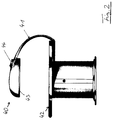
- Fig. 2 shows a modification of a device according to the invention in the form of a suction hood 40, which has a bow-shaped Holding element 41 is attached above a table 42 on the underside of the in table top in a manner not shown and attached with the inclusion of electrical lines.
- the modified device 40 contains on its underside a large-area filter 43 and, in a manner not shown, a suction fan and a sound-absorbing chamber which is adapted to the shape of the hood and has corresponding outer fillings of insulating material. The cleaned air is then pushed up out of the hood through an outlet opening 44 in which a multi-perforated plate is arranged.
- lighting devices can also be integrated on the underside of the hood, preferably next to the filter inlet openings.
Abstract
Description
Die Erfindung betrifft eine Vorrichtung zum Absaugen und Reinigen von Grill-, Gar- und Kochdünsten sowie zum Ausblasen gereinigter Luft.The invention relates to a device for extracting and cleaning grill, cooking and cooking vapors and for blowing out cleaned air.
Bezweckt wird mit der Erfindung die Schaffung einer derartigen Vorrichtung, die einfach und problemlos im Zusammenhang mit einem sogenannten Koch-, Grill- und Gartisch eingesetzt werden kann, der Gegenstand einer älteren Patentanmeldung des Anmelders ist. Die erfindungsgemäße Vorrichtung soll nicht nur als separate Einheit verwendbar sein, sondern auch die Möglichkeit einer Integration in ein zentrales Tischbein bieten, wobei das eigentliche Absaugen aus einem Bereich oberhalb des Tisches vorgenommen werden soll. Außerdem wird die Schaffung einer besonders leise arbeitenden Vorrichtung bezweckt, die die Eigenschaften einer guten Absaug- und Reinigungsleistung mit denen einer nicht störenden Abgabe von gereinigter Abluft verbindet, ohne daß der Geräuschpegel beim Betrieb gesprächsstörend wirkt.The aim of the invention is to provide such a device which can be used simply and without problems in connection with a so-called cooking, grill and garden table which is the subject of an earlier patent application by the applicant. The device according to the invention should not only be usable as a separate unit, but also offer the possibility of integration into a central table leg, the actual suctioning being to be carried out from an area above the table. In addition, the aim is to create a particularly quiet device that combines the properties of a good suction and cleaning performance with those of a non-distracting discharge of cleaned exhaust air, without the noise level having an adverse effect on the conversation.
Erfindungsgemäß wird dieses Ziel durch eine Vorrichtung mit den Merkmalen des Anspruchs 1 erreicht. Bevorzugte weitere Ausgestaltungen der Erfindung sind den nachgeordneten Ansprüchen 2 bis 14 zu entnehmen.According to the invention, this aim is achieved by a device with the features of claim 1. Preferred further developments of the invention can be found in the subordinate claims 2 to 14.
Aufgrund der erfindungsgemäßen Ausgestaltung ist es möglich, die Vorrichtung als separate oder integrationsfähige Einheit für einen Grill-, Gar- und Kochtisch zu verwenden, wobei auch eine Nachrüstmöglichkeit aufgrund der erfindungsgemäßen Konstruktion ermöglicht wird.Because of the configuration according to the invention, it is possible to use the device as a separate or integrable unit for a grill, cooking and cooking table, with the possibility of retrofitting also being made possible due to the construction according to the invention.
Die erfindungsgemäße Vorrichtung läßt sich einerseits als komplette Einheit aus Filter, Ansaugmotor und Dämpfungskammer in einem haubenähnlichen Element mit Abluftöffnungen integrieren, wobei das haubenähnliche Element über dem Tisch mittels eines bogenförmigen Bügels haltbar ist, der entweder mit geeigneter Befestigungsmaßnahme am Tisch selbst, vorzugsweise unter der Tischplatte, oder auf einem separaten Stativ befestigt ist. Besonders günstig ist die Ausgestaltung der Vorrichtung in einem nach Art einer zylindrischen Patrone gekapselt ausgebildeten Gehäuse, das als Einheit problemlos in ein hohles Tischbeinprofil auch nachträglich eingesetzt werden kann. Dabei erfolgt das Ansaugen von Luft wiederum über einen haubenähnlichen Aufbau mit einer bügelförmigen Rohrleitung bis unter die Tischplatte zu einem seitlich ausgeführten Ansaugstutzen oder über eine ringförmige Ansaugkammer, die Absaugschlitze im Bereich der Tischplatte aufweist, der mit der Vorrichtung selbst verbunden ist, und die gereinigte Luft wird im Bereich des Tischfußes über eine vom Boden beabstandete Viellochplatte diffus ausgeblasen.The device according to the invention can be integrated on the one hand as a complete unit consisting of filter, suction motor and damping chamber in a hood-like element with exhaust air openings, the hood-like element being stable above the table by means of an arc-shaped bracket, which can either be attached to the table itself, preferably under the table top, using a suitable fastening measure , or is attached to a separate tripod. The design of the device in a housing which is encapsulated in the manner of a cylindrical cartridge and which can be used retrospectively as a unit in a hollow table leg profile is particularly favorable. In this case, air is sucked in again via a hood-like structure with a bow-shaped pipeline to below the table top to a suction port on the side or via an annular suction chamber that has suction slots in the area of the table top that is connected to the device itself, and the cleaned air is blown out diffusely in the area of the table base via a multi-hole plate spaced from the floor.
Die Schalldämpfung wird bei der in der Haube selbst integrierten Vorrichtung durch übliches Dämmaterial, insbesondere Antidröhnmasse auf Bitumbasis oder dergleichen, wie aus dem Automobilbau bekannt, vorgenommen. Bei der Ausgestaltung der Vorrichtung als zylindrische Patrone ist in das Gehäuse eine hohlzylindrische Schalldämpfungskammer integriert, deren Innenwand Schalldämp fungslöcher aufweist und in die in axialer Richtung Schalldämpfungskulissen besitzt, während wiederum der Auslaß mit einer Viellochplatte versehen ist. Außerdem sind in günstiger Weise zwischen Absauggebläse und Schalldämpfungskammer Strömungsleitflächen angeordnet, um die Luftströmung zur Unterstützung der Schalldämpfungswirkung zu verändern.In the device integrated in the hood itself, the soundproofing is carried out by means of customary insulating material, in particular anti-drumming compound based on bitumen or the like, as is known from automobile construction. In the design of the device as a cylindrical cartridge, a hollow cylindrical sound-absorbing chamber is integrated into the housing, the inner wall of which is sound-absorbing has holes and in the axial direction has noise damping, while the outlet is provided with a multi-hole plate. In addition, flow guide surfaces are advantageously arranged between the suction fan and the sound-absorbing chamber in order to change the air flow in order to support the sound-absorbing effect.
Die Schalldämpfungskammer und das Absauggebläse sind vorzugsweise axial nebeneinander angeordnet, wobei der Filter entweder ebenfalls vor dem Absauggebläse in das Gehäuse integriert ist oder als Schieber mit Austauschelement vor dem Ansaugstutzen und damit außerhalb der zylindrischen Patrone vorgesehen ist.The soundproofing chamber and the suction fan are preferably arranged axially next to one another, the filter either being integrated in the housing in front of the suction fan or being provided as a slide with a replacement element in front of the suction nozzle and thus outside the cylindrical cartridge.
Zweckmäßigerweise ist weiterhin im Bereich der Absaughaube eine Beleuchtungseinrichtung vorgesehen. Außerdem können auch noch Schalterelemente für die Vorrichtung im Bereich der Absaughaube am Gehäuse selbst vorgesehen sein.A lighting device is also expediently provided in the area of the suction hood. In addition, switch elements can also be provided for the device in the area of the suction hood on the housing itself.
Nachfolgend wird die Erfindung unter Bezugnahme auf die beigefügten Zeichnungen näher erläutert. Es zeigen:
- Fig. 1
- einen Schnitt durch ein Ausführungsbeispiel einer erfindungsgemäßen Absaugvorrichtung, die in ein Tischbein eines Grill-, Gar- und Kochtisches integriert ist; und
- Fig. 2
- ein anderes Ausführungsbeispiel eine Absaugvorrichtung, die in eine Absaughaube integriert und über einen Bügel mit einem Grill-, Gar- und Kochtisch unterhalb der Tischplatte befestigt ist.
- Fig. 1
- a section through an embodiment of a suction device according to the invention, which is integrated into a table leg of a grill, cooking and cooking table; and
- Fig. 2
- another embodiment, a suction device which is integrated in a suction hood and is attached via a bracket with a grill, cooking and cooking table below the table top.
Fig. 1 zeigt einen teilweise aufgeschnittenen Grill-, Gar- und Kochtisch 11, der aus einer Tischplatte 12 und einem zylindrischen Beinabschnitt 13 besteht, wobei an der Unterseite des Tisches 11 Füße 14 angeordnet sind. Der Beinabschnitt 13 ist aufgeschnitten, um den Aufbau einer eingesetzten erfindungsgemäßen Vorrichtung 10 zu veranschaulichen.Fig. 1 shows a partially cut grill, cooking and cooking table 11, which consists of a
Die Vorrichtung 10 weist ein zylindrisches patronenähnliches Gehäuse 15, vorzugsweise aus Zinkblech, auf, dessen Umgebung zum Inneren des Beinabschnitts 13 mit Dämmaterial 16, beispielsweise Glaswolle und/oder Mineralwolle und/oder Steinwolle gefüllt ist.The
Im Inneren des Gehäuses 15 befindet sich ein hohlzylindrischer Einsatz 17, der mit Schalldämpfungslöchern 18 versehen ist. Am Bodenbereich wird das Gehäuse 15 durch eine Viellochplatte 19 geschlossen, durch die gereinigte Abluft zur weiteren Verbesserung der Dämpfung diffus austritt, wobei die Löchergröße und Löcherzahl auf die üblichen Betriebsbereiche eines in dem Gehäuse ebenfalls angeordneten Absauggebläses 20 abgestimmt sind. Das Absauggebläse 20 besitzt schematisiert angedeutete Flügel 21, die durch einen zentral vorgesehenen Motor 22 derart angetrieben werden, daß eine Luftströmung durch das Absauggebläse nach unten in den Bereich der im Inneren des Zylinders 17 gebildeten Schalldämpfungskammer 23 erfolgt.Inside the
Vor der Schalldämpfungskammer 23 sind Strömungsleitflächen 24 angeordnet, durch die die Strömung der Luft zur Verbesserung der Schalldämpfwirkung verwirbelnd in die Schalldämpfungskammer 23 leitbar ist. Oberhalb des Absauggebläse 20 befindet sich ein Ansaugstutzen 25, an den ein abgewinkeltes Ansaugrohr 26 befestigt ist, das seitlich aus dem Bereich des Beinabschnitts 13 zu einer Filtereinrichtung 27 herausgeführt ist. Die Filtereinrichtung 27 weist einen mit Aktivkohle gebildeten Filterschieber 28 sowie einen Einsteckstutzen 29 für den Anschluß eines nicht dargestellten Absaugrohres auf, das zu einer über dem Tisch 11 anzuordnenden Absaughaube führt. Der Raum oberhalb der Schalldämpfungskammer 23 um das Absauggebläse 20 und das Ansaugrohr 26 herum ist ebenfalls mit einem Dämmaterial 30 schalldämmend gefüllt, das identisch mit dem Dämmaterial 16 sein und auch wenigstens teilweise Antidröhnmassen auf Bitumbasis oder dergleichen enthalten kann.Flow guiding
Fig. 2 zeigt eine Abwandlung einer erfindungsgemäßen Vorrichtung in Gestaltung als Absaughaube 40, die über ein bügelförmiges Halteelement 41 über einem Tisch 42 an der Unterseite des in Tischplatte in nicht dargestellter Weise einrastend und unter Aufnahme elektrischer Leitungen angebracht ist. Die modifizierte Vorrichtung 40 enthält an ihrer Unterseite einen Großflächenfilter 43 sowie in nicht dargestellter Weise ein Absauggebläse und eine entsprechend der Form der Haube angepaßte Schalldämpfungskammer mit entsprechenden Dämmaterialaußenfüllungen. Die gereinigte Luft wird dann aus der Haube durch eine Auslaßöffnung 44 nach oben herausgedrückt, in der ein Viellochblech angeordnet ist. In nicht dargestellter Weise können weiterhin Beleuchtungseinrichtungen an der Unterseite der Haube vorzugsweise neben die Filtereinlaßöffnungen, integriert sein.Fig. 2 shows a modification of a device according to the invention in the form of a
Claims (15)
einem Gehäuse (15),
einem Filter (27,28,43),
einem elektrischen Absauggebläse (20) durch das die betreffenden Dünste durch den Filter (27,28,43) zum Reinigen absaugbar sind, und aus
einer Schalldämpfungskammer (23), die dem Absauggebläse (20) nachgeordnet ist und aus der die gereinigte Luft ausblasbar ist, wobei wenigstens das Absauggebläse (20) und die Schalldämpfungskammer (23) mit Dämmaterial (30) in dem Gehäuse (15) gekapselt angeordnet sind.Device (10; 40) for extracting and cleaning grill, cooking and cooking fumes and for blowing out cleaned air, consisting of
a housing (15),
a filter (27,28,43),
an electric suction fan (20) through which the relevant vapors can be suctioned through the filter (27, 28, 43) for cleaning, and out
a sound damping chamber (23), which is arranged downstream of the suction fan (20) and from which the cleaned air can be blown out, at least the suction fan (20) and the sound damping chamber (23) being arranged encapsulated in the housing (15) with insulating material (30) .
Applications Claiming Priority (2)
| Application Number | Priority Date | Filing Date | Title |
|---|---|---|---|
| DE19934326837 DE4326837A1 (en) | 1993-08-10 | 1993-08-10 | Suction device |
| DE4326837 | 1993-08-10 |
Publications (1)
| Publication Number | Publication Date |
|---|---|
| EP0640798A1 true EP0640798A1 (en) | 1995-03-01 |
Family
ID=6494863
Family Applications (1)
| Application Number | Title | Priority Date | Filing Date |
|---|---|---|---|
| EP94112424A Withdrawn EP0640798A1 (en) | 1993-08-10 | 1994-08-09 | Extraction system |
Country Status (2)
| Country | Link |
|---|---|
| EP (1) | EP0640798A1 (en) |
| DE (1) | DE4326837A1 (en) |
Cited By (2)
| Publication number | Priority date | Publication date | Assignee | Title |
|---|---|---|---|---|
| EP2554918A1 (en) | 2011-08-05 | 2013-02-06 | BSH Bosch und Siemens Hausgeräte GmbH | Device for extracting air from a hob |
| CN110762576A (en) * | 2019-11-04 | 2020-02-07 | 广州视源电子科技股份有限公司 | Noise reduction method and device for range hood, range hood and storage medium |
Families Citing this family (2)
| Publication number | Priority date | Publication date | Assignee | Title |
|---|---|---|---|---|
| DE29600352U1 (en) * | 1996-01-12 | 1996-03-07 | Wirth Arnold | table |
| CN103398407B (en) * | 2013-08-23 | 2016-08-10 | 周洪贤 | A kind of oil smoke Separated sound deadening purifying box |
Citations (4)
| Publication number | Priority date | Publication date | Assignee | Title |
|---|---|---|---|---|
| BE860545A (en) * | 1977-11-07 | 1978-03-01 | P V B A Hilaire Lannoy En Zone | VAPOR EXTRACTION DEVICE |
| EP0183082A1 (en) * | 1984-11-24 | 1986-06-04 | Siegfried Marzari | Grilling table |
| EP0301640A1 (en) * | 1987-07-27 | 1989-02-01 | ELICA S.p.A. | Suction hood for fumes, especially for domestic kitchens, with large collection area |
| DE4104963C1 (en) * | 1991-02-18 | 1992-06-25 | Bosch-Siemens Hausgeraete Gmbh, 8000 Muenchen, De |
Family Cites Families (4)
| Publication number | Priority date | Publication date | Assignee | Title |
|---|---|---|---|---|
| FR1156581A (en) * | 1956-07-26 | 1958-05-19 | Improvements made to devices for the suction of vapors, in particular steams | |
| DE1912186A1 (en) * | 1969-03-11 | 1970-09-17 | Alois Otting | Device for peeling off lawn areas with at least one peeling device which has knives to be carried out under the lawn |
| WO1989006773A1 (en) * | 1988-01-14 | 1989-07-27 | The Yano Corporation | Cooking apparatus ventilation system |
| DE9208717U1 (en) * | 1992-06-30 | 1992-09-17 | Buercher, Friedrich, 8029 Sauerlach, De |
-
1993
- 1993-08-10 DE DE19934326837 patent/DE4326837A1/en not_active Withdrawn
-
1994
- 1994-08-09 EP EP94112424A patent/EP0640798A1/en not_active Withdrawn
Patent Citations (4)
| Publication number | Priority date | Publication date | Assignee | Title |
|---|---|---|---|---|
| BE860545A (en) * | 1977-11-07 | 1978-03-01 | P V B A Hilaire Lannoy En Zone | VAPOR EXTRACTION DEVICE |
| EP0183082A1 (en) * | 1984-11-24 | 1986-06-04 | Siegfried Marzari | Grilling table |
| EP0301640A1 (en) * | 1987-07-27 | 1989-02-01 | ELICA S.p.A. | Suction hood for fumes, especially for domestic kitchens, with large collection area |
| DE4104963C1 (en) * | 1991-02-18 | 1992-06-25 | Bosch-Siemens Hausgeraete Gmbh, 8000 Muenchen, De |
Cited By (3)
| Publication number | Priority date | Publication date | Assignee | Title |
|---|---|---|---|---|
| EP2554918A1 (en) | 2011-08-05 | 2013-02-06 | BSH Bosch und Siemens Hausgeräte GmbH | Device for extracting air from a hob |
| DE102011080485A1 (en) | 2011-08-05 | 2013-02-07 | BSH Bosch und Siemens Hausgeräte GmbH | Device for extracting air from a hob |
| CN110762576A (en) * | 2019-11-04 | 2020-02-07 | 广州视源电子科技股份有限公司 | Noise reduction method and device for range hood, range hood and storage medium |
Also Published As
| Publication number | Publication date |
|---|---|
| DE4326837A1 (en) | 1995-02-16 |
Similar Documents
| Publication | Publication Date | Title |
|---|---|---|
| DE602004000181T2 (en) | Dust extraction hood for a hand tool | |
| EP2108894A1 (en) | Extractor hood | |
| DE102007061982A1 (en) | Fume extraction device for extracting e.g. cooking steam, has housing comprising inlet side, and two filtering devices assigned to set of filtering devices of different design, where filtering devices have sealing element | |
| EP0640798A1 (en) | Extraction system | |
| DE102005008373A1 (en) | Fume hood for domestic cooker has a bath-shaped filter device, forming underside of drawer | |
| WO2009062809A2 (en) | Extractor device | |
| DE2747996C3 (en) | Device for separating dust-like parts from an air stream | |
| DE19530785C1 (en) | Air purifier | |
| EP2072907A2 (en) | Fume hood device | |
| EP2072908B1 (en) | Fume extracting device | |
| DE20122340U1 (en) | Range hood used in kitchens comprises a fan section having a housing with a suction opening | |
| DE202005005739U1 (en) | Non smokers protection device e.g. for removing bad air, has air convection generator with blower unit and extraction unit with blower unit creates barrier curtain by blowing out air separating | |
| DE102020130485A1 (en) | Air circulation device for a hob and functional unit consisting of a hob, a piece of furniture and an air circulation device | |
| DE4104965C2 (en) | Housing for a fan | |
| EP2072906A2 (en) | Fume hood device | |
| EP0943871B1 (en) | Extraction hood for kitchens | |
| BE1030826B1 (en) | Air exhaust adapter, extension element, extractor system and assembly method | |
| EP3825613B1 (en) | Extractor hood | |
| DE102010001140B4 (en) | Vacuum cleaner with mesh guard | |
| DE202006013496U1 (en) | Component part carrier e.g. switch cabinet, for e.g. telecommunication unit, has ventilation chambers provided in wall areas, and connected with vent opening, where chambers are partially lined with sound reducing material | |
| WO2006037642A1 (en) | Device for protecting non-smokers | |
| EP1654500A1 (en) | Filter system | |
| WO2009077284A2 (en) | Extractor hood and filter for an extractor hood | |
| DE102007056336A1 (en) | Manually guided blower for use in collecting yard materials e.g. leaves, has several micro-switches that are actuated, when attachments are secured to intake and discharge openings of housing | |
| DE2234911C3 (en) | Hood designed as a tubular intake silencer for gas or oil burners |
Legal Events
| Date | Code | Title | Description |
|---|---|---|---|
| PUAI | Public reference made under article 153(3) epc to a published international application that has entered the european phase |
Free format text: ORIGINAL CODE: 0009012 |
|
| AK | Designated contracting states |
Kind code of ref document: A1 Designated state(s): AT BE CH DE DK ES FR GB GR IE IT LI LU MC NL PT SE |
|
| RBV | Designated contracting states (corrected) |
Designated state(s): AT BE CH DE DK FR GB IT LI NL SE |
|
| STAA | Information on the status of an ep patent application or granted ep patent |
Free format text: STATUS: THE APPLICATION IS DEEMED TO BE WITHDRAWN |
|
| 18D | Application deemed to be withdrawn |
Effective date: 19950902 |