EP0640765A1 - Elektromechanische Vorrichtung um eine Pumpe in Abwesenheit von Wasser zu Schützen - Google Patents
Elektromechanische Vorrichtung um eine Pumpe in Abwesenheit von Wasser zu Schützen Download PDFInfo
- Publication number
- EP0640765A1 EP0640765A1 EP94830191A EP94830191A EP0640765A1 EP 0640765 A1 EP0640765 A1 EP 0640765A1 EP 94830191 A EP94830191 A EP 94830191A EP 94830191 A EP94830191 A EP 94830191A EP 0640765 A1 EP0640765 A1 EP 0640765A1
- Authority
- EP
- European Patent Office
- Prior art keywords
- pump
- water
- membrane
- contacts
- moving
- Prior art date
- Legal status (The legal status is an assumption and is not a legal conclusion. Google has not performed a legal analysis and makes no representation as to the accuracy of the status listed.)
- Withdrawn
Links
- XLYOFNOQVPJJNP-UHFFFAOYSA-N water Substances O XLYOFNOQVPJJNP-UHFFFAOYSA-N 0.000 title claims abstract description 36
- 239000012528 membrane Substances 0.000 claims abstract description 18
- 238000009434 installation Methods 0.000 description 5
- 230000000087 stabilizing effect Effects 0.000 description 2
- 238000010586 diagram Methods 0.000 description 1
- 230000005611 electricity Effects 0.000 description 1
- 238000012423 maintenance Methods 0.000 description 1
- 239000004576 sand Substances 0.000 description 1
- 239000003381 stabilizer Substances 0.000 description 1
Images

Classifications
-
- H—ELECTRICITY
- H01—ELECTRIC ELEMENTS
- H01H—ELECTRIC SWITCHES; RELAYS; SELECTORS; EMERGENCY PROTECTIVE DEVICES
- H01H35/00—Switches operated by change of a physical condition
- H01H35/24—Switches operated by change of fluid pressure, by fluid pressure waves, or by change of fluid flow
- H01H35/34—Switches operated by change of fluid pressure, by fluid pressure waves, or by change of fluid flow actuated by diaphragm
-
- F—MECHANICAL ENGINEERING; LIGHTING; HEATING; WEAPONS; BLASTING
- F04—POSITIVE - DISPLACEMENT MACHINES FOR LIQUIDS; PUMPS FOR LIQUIDS OR ELASTIC FLUIDS
- F04B—POSITIVE-DISPLACEMENT MACHINES FOR LIQUIDS; PUMPS
- F04B49/00—Control, e.g. of pump delivery, or pump pressure of, or safety measures for, machines, pumps, or pumping installations, not otherwise provided for, or of interest apart from, groups F04B1/00 - F04B47/00
- F04B49/02—Stopping, starting, unloading or idling control
- F04B49/022—Stopping, starting, unloading or idling control by means of pressure
Definitions
- the invention relates to an electromechanical device capable of automatically checking the presence of water in a domestic distribution circuit of a building, of an industrial installation or other, for the protection of the circulating pump of said circuit.
- the electromechanical device to which the invention relates has been developed, and is easily understood, simply fitted and highly reliable, particularly in wet areas such as those where these gadgets are fitted.
- the device protects the pump from damage due to a lack of water flow through the pump.
- Said moving element is also provided with a member for manual operation, particularly for turning the pump on.
- the moving contacts may be elastic and capable of bridging pairs of corresponding fixed contacts.
- the moving contacts may be carried by a cross-piece of said moving element.
- the device in question may be fitted, in the outlet pipe of the pump at the inlet of a waterworks in combination with a pressure stabilizing gadget which, in turn, controls the pump used for distributing the water necessary for the maintenance of the internal pressure and of the water capacity.
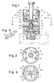
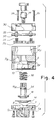
- the number 1 indicates a base, with a union 1A for branching from an outlet pipe M, illustrated schematically in Fig. 1; a hole 5 in said union 1A enables water from the pipe M to enter a cavity 7 in the base 1.
- the number 9 indicates a body forming a casing, which has a through cavity shaped to form a first lower cylindrical chamber 10 and a second upper chamber 12. The base 1 and the casing 9 are joined by pressing a flexible membrane 14 peripherally to form a seal.
- the chamber 10 houses a piston 16 forming part of a moving element which comprises, in addition to the piston 16, and fixed to its rod 16A, an insulating contact support cross-piece 22 and an operating member 24; the members 16, 22, 24 form a moving element.
- the cross-piece 22 is located in the upper chamber 12 and is guided by longitudinal grooves 12A in the said chamber.
- the cross-piece 22 carries two transverse elastically movable contacts 26.
- Each of said two contacts 26 can interact with two fixed contacts 28 connected to external connecting terminals; said contacts 28 are supported by a cover 30; a cap 32 may close off the chamber 12 and the space occupied by the terminals of the fixed contacts 28.
- the cover 30 and the cap 32 are fixed with screws 33 to the casing 9.
- the rod 16A passes through a thick diaphragm 9S, which separates the chambers 10 and 12; the control member 24, which may be screwed into the end of the rod 16A from the outside, passes through the cover 30 and the cap 32.
- An annular seal 34 acts between the diaphragm 9S and the rod 16A, and is housed in an annular channel of the rod 16A or of the diaphragm 9S, to prevent the passage of water to the chamber 12.
- a spring 36 surrounding the rod 16A of the piston 16 acts on the diaphragm 9S and pushes the piston 16 against the membrane 14.
- the device is fixed to the piping M of the water supply network by means of the union 1A of the base 1.
- the hole 5 enables the cavity 7 to communicate with the pipe M, so that the pressure prevailing in this pipe acts on the membrane 14, which in turn pushes the piston 16 and the whole element 16, 22, 24, including the contacts 26, against the action of the spring 36.
- said casing 9 has one or more small-diameter holes 9F in its sides, for the drainage of the water which may be filtered by the membrane 14, and to avoid impeding the reduction in volume of the chamber 10.
- the water contained in the cavity 7 flows out through said hole 5, causing the piston 16 to descend together with the contact support cross-piece 22 with said moving contacts 26, which are moved away from the fixed contacts 28.
- the electrical contacts therefore cut off the supply of electricity to the pump which stops until the water returns to normal levels within the water distribution network.
- the external operation member 24 enables the element 16, 22, 24 and consequently the contact support cross-piece 22 to be lifted manually even when the water has not returned to the waterworks, or when operation of the pump is required for other purposes.
- Figs. 6, 7 and 8 show three possible types of installation of the device, indicated here in a general way by HS; P indicates the pump protected by it, M indicates the outlet to the consumer and A indicates the inlet of the pump P.
- a pressure stabilizer SP may advantageously interact with the device HS.
- Fig. 6 there is a direct connection to the water distribution network.
- the operation of the pump is interrupted.
- network pressure returns, the device HS is automatically reset by the thrust of the water on the membrane 14.
- the pump has its inlet A and a one-way valve A1 immersed in a storage tank or cistern C.
- the operation of the pump is interrupted, and it is necessary to reset it manually; as soon as the water level is regained in C, the device HS may be manually reset; the resetting operation takes only a few seconds if the pump P has its one-way valve A1.
- the resetting may be repeated one or more times before giving up and intervening to remove the causes.
- the device HS may be adjusted to switch off when the water pressure is lower than 0.3/0.5 bar. If the pressure returns naturally (water main) the device is automatically reset, while in cases in which the pump is immersed, the resetting will be manual or electronically controlled with the corresponding intervention of the timer.
- the device is extremely simple in mechanical terms and resolves in an optimal manner all the problems which have hitherto resulted in considerable inconvenience and economic losses.
Landscapes
- Engineering & Computer Science (AREA)
- Physics & Mathematics (AREA)
- Fluid Mechanics (AREA)
- Mechanical Engineering (AREA)
- General Engineering & Computer Science (AREA)
- Flow Control (AREA)
- Pipeline Systems (AREA)
- Separation Using Semi-Permeable Membranes (AREA)
- Control Of Positive-Displacement Pumps (AREA)
Applications Claiming Priority (2)
| Application Number | Priority Date | Filing Date | Title |
|---|---|---|---|
| ITLU930005 | 1993-04-28 | ||
| IT93LU000005A ITLU930005A1 (it) | 1993-04-28 | 1993-04-28 | Dispositivo elettro-meccanico per il controllo in automatico di impianti idrici in genere |
Publications (1)
| Publication Number | Publication Date |
|---|---|
| EP0640765A1 true EP0640765A1 (de) | 1995-03-01 |
Family
ID=11356223
Family Applications (1)
| Application Number | Title | Priority Date | Filing Date |
|---|---|---|---|
| EP94830191A Withdrawn EP0640765A1 (de) | 1993-04-28 | 1994-04-22 | Elektromechanische Vorrichtung um eine Pumpe in Abwesenheit von Wasser zu Schützen |
Country Status (3)
| Country | Link |
|---|---|
| US (1) | US5672049A (de) |
| EP (1) | EP0640765A1 (de) |
| IT (1) | ITLU930005A1 (de) |
Cited By (3)
| Publication number | Priority date | Publication date | Assignee | Title |
|---|---|---|---|---|
| ES2146135A1 (es) * | 1997-07-29 | 2000-07-16 | Sosa Rincon Dionisio | Dispositivo para el pare automatico de motoresbomba. |
| WO2005100792A1 (en) * | 2004-04-14 | 2005-10-27 | Gilberto Tadeu Pires De Paula | Pressure and flow controller for a pump |
| CN102878089A (zh) * | 2012-10-17 | 2013-01-16 | 海门市海菱碳业有限公司 | 一种改进的智能水泵 |
Families Citing this family (18)
| Publication number | Priority date | Publication date | Assignee | Title |
|---|---|---|---|---|
| US6099264A (en) * | 1998-08-27 | 2000-08-08 | Itt Manufacturing Enterprises, Inc. | Pump controller |
| US6563064B2 (en) * | 2000-12-21 | 2003-05-13 | Itt Manufacturing Enterprises, Inc. | Fluid flow switch sensing device having a test button |
| US6607360B2 (en) | 2001-07-17 | 2003-08-19 | Itt Industries Flojet | Constant pressure pump controller system |
| AU2002342165A1 (en) * | 2001-10-31 | 2003-05-12 | Stephen Gaiski | A method and an apparatus for selectively dispensing a material |
| US6552284B1 (en) | 2002-02-25 | 2003-04-22 | Derrin T. Drago | Water pump low pressure cutoff switch |
| US6867383B1 (en) * | 2003-03-28 | 2005-03-15 | Little Giant Pump Company | Liquid level assembly with diaphragm seal |
| US7084363B1 (en) * | 2003-12-10 | 2006-08-01 | Trusty Warns, Inc. | Variable differential adjustor |
| US20050279413A1 (en) * | 2004-06-18 | 2005-12-22 | Der-Fan Shen | Flow control switch |
| CN100593831C (zh) * | 2005-06-23 | 2010-03-10 | 王正宗 | 充气产品的气压开关 |
| CN100468596C (zh) * | 2005-07-07 | 2009-03-11 | 王正宗 | 充气产品的气压开关的缓冲装置 |
| DE102005032158A1 (de) * | 2005-07-09 | 2007-01-11 | Suco Robert Scheuffele Gmbh & Co. Kg | Druckschalter |
| US7931447B2 (en) | 2006-06-29 | 2011-04-26 | Hayward Industries, Inc. | Drain safety and pump control device |
| US7256361B1 (en) * | 2006-12-27 | 2007-08-14 | Su-Yun Lee | Pressure switch |
| US10030647B2 (en) | 2010-02-25 | 2018-07-24 | Hayward Industries, Inc. | Universal mount for a variable speed pump drive user interface |
| EP3954352B1 (de) | 2013-03-15 | 2024-08-21 | Hayward Industries, Inc. | Steuerungssystem für modulares schwimmbad/spa |
| US11720085B2 (en) | 2016-01-22 | 2023-08-08 | Hayward Industries, Inc. | Systems and methods for providing network connectivity and remote monitoring, optimization, and control of pool/spa equipment |
| US10363197B2 (en) | 2016-01-22 | 2019-07-30 | Hayward Industries, Inc. | Systems and methods for providing network connectivity and remote monitoring, optimization, and control of pool/spa equipment |
| US10718337B2 (en) | 2016-09-22 | 2020-07-21 | Hayward Industries, Inc. | Self-priming dedicated water feature pump |
Citations (2)
| Publication number | Priority date | Publication date | Assignee | Title |
|---|---|---|---|---|
| DE2455980A1 (de) * | 1974-11-27 | 1976-08-12 | Bosch Gmbh Robert | Schalter, insbesondere zur ueberwachung von zweikreis-bremsanlagen in kraftfahrzeugen |
| US4200775A (en) * | 1978-06-19 | 1980-04-29 | Furnas Electric Company | Pressure responsive switch with low pressure cutoff |
Family Cites Families (12)
| Publication number | Priority date | Publication date | Assignee | Title |
|---|---|---|---|---|
| US2118130A (en) * | 1937-07-16 | 1938-05-24 | Westinghouse Air Brake Co | Compressor control device |
| US2554266A (en) * | 1948-12-02 | 1951-05-22 | Bendix Aviat Corp | Pressure actuated switch |
| AT247801B (de) * | 1960-10-10 | 1966-06-27 | Odd Fredheim Johnsen | Druckgesteuertes Ventil, insbesondere für Wasserversorgungssysteme |
| US3235683A (en) * | 1961-04-12 | 1966-02-15 | Beeman Lyle | Air compressor control mechanism |
| US3143969A (en) * | 1961-05-11 | 1964-08-11 | Roy S Sanford & Company | Liquid pump and meter |
| US3139493A (en) * | 1962-08-28 | 1964-06-30 | Furnas Electric Co | Pressure switch with low pressure cut-out |
| FR2106788A5 (de) * | 1970-09-24 | 1972-05-05 | Equip Menager Fse | |
| US4118148A (en) * | 1976-05-11 | 1978-10-03 | Gulf Oil Corporation | Downhole well pump control system |
| JPS54162858U (de) * | 1978-05-04 | 1979-11-14 | ||
| US4848097A (en) * | 1988-07-18 | 1989-07-18 | Roberts Mark J | Apparatus for transferring water from a container to a refrigerator ice maker |
| US5320280A (en) * | 1992-06-19 | 1994-06-14 | Graco Inc. | Pneumatically controlled spraying system having a diaphragm-operated switch |
| US5292232A (en) * | 1993-01-19 | 1994-03-08 | Graco Inc. | Liquid pump pressure control system |
-
1993
- 1993-04-28 IT IT93LU000005A patent/ITLU930005A1/it not_active Application Discontinuation
-
1994
- 1994-04-22 EP EP94830191A patent/EP0640765A1/de not_active Withdrawn
- 1994-04-26 US US08/233,354 patent/US5672049A/en not_active Expired - Fee Related
Patent Citations (2)
| Publication number | Priority date | Publication date | Assignee | Title |
|---|---|---|---|---|
| DE2455980A1 (de) * | 1974-11-27 | 1976-08-12 | Bosch Gmbh Robert | Schalter, insbesondere zur ueberwachung von zweikreis-bremsanlagen in kraftfahrzeugen |
| US4200775A (en) * | 1978-06-19 | 1980-04-29 | Furnas Electric Company | Pressure responsive switch with low pressure cutoff |
Cited By (3)
| Publication number | Priority date | Publication date | Assignee | Title |
|---|---|---|---|---|
| ES2146135A1 (es) * | 1997-07-29 | 2000-07-16 | Sosa Rincon Dionisio | Dispositivo para el pare automatico de motoresbomba. |
| WO2005100792A1 (en) * | 2004-04-14 | 2005-10-27 | Gilberto Tadeu Pires De Paula | Pressure and flow controller for a pump |
| CN102878089A (zh) * | 2012-10-17 | 2013-01-16 | 海门市海菱碳业有限公司 | 一种改进的智能水泵 |
Also Published As
| Publication number | Publication date |
|---|---|
| ITLU930005A1 (it) | 1994-10-28 |
| ITLU930005A0 (it) | 1993-04-28 |
| US5672049A (en) | 1997-09-30 |
Similar Documents
| Publication | Publication Date | Title |
|---|---|---|
| EP0640765A1 (de) | Elektromechanische Vorrichtung um eine Pumpe in Abwesenheit von Wasser zu Schützen | |
| US5584316A (en) | Hydrothermal stabilizer and expansion tank system | |
| RU2116810C1 (ru) | Клапан для противопожарной установки | |
| EP2757204B1 (de) | Toilette ohne Schwerkraft-Spülung | |
| EP3385971A1 (de) | Elektronischer druckschalter | |
| SU1005671A3 (ru) | Устройство дл дистанционного управлени электрическим выключателем | |
| AU674611B2 (en) | Electromechanical device for the protection of a pump in waterworks of various types, in the absence of water | |
| CA2118069A1 (en) | Electromechanical device for the protection of a pump in waterworks of various types in the absence of water | |
| AU781590B2 (en) | High gain fluid control valve assembly | |
| US5169291A (en) | Water heater with shut-off valve | |
| US4421459A (en) | Fluid level control apparatus | |
| US6552284B1 (en) | Water pump low pressure cutoff switch | |
| AU2008243272A1 (en) | Apparatus for Switching Between Mains Water and Stored Water Supplies | |
| WO2006086506A3 (en) | Activation device for sump pumps | |
| US3902028A (en) | Pressure responsive switch | |
| EP1479911B1 (de) | Kleine Druckspeicheranordnung für Trinkwassersystem | |
| US6047721A (en) | Air introduction device for a hydro-pneumatic reservoir | |
| KR100198880B1 (ko) | 부동전 | |
| US6572340B2 (en) | Pressure motive pump assembly comprising a float, an over center linkage mechanism, and a pair of positive stop or abutment means for ensuring over center tripping action | |
| RU2065093C1 (ru) | Устройство блокировки гидравлической системы | |
| US1056709A (en) | Pump. | |
| JP4285610B2 (ja) | 予作動式スプリンクラー設備 | |
| KR100727599B1 (ko) | 이중 차단 시스템을 갖는 수위조절장치 및 그 제어방법,그리고 이를 이용한 정수기 | |
| WO2026088180A1 (en) | Closed pressure vessel with a movable lenticular diaphragm and automatic air release function | |
| PL195201B1 (pl) | Zespół pompowy pompowni, zwłaszcza odwadniających |
Legal Events
| Date | Code | Title | Description |
|---|---|---|---|
| PUAI | Public reference made under article 153(3) epc to a published international application that has entered the european phase |
Free format text: ORIGINAL CODE: 0009012 |
|
| AK | Designated contracting states |
Kind code of ref document: A1 Designated state(s): AT BE DE DK ES FR GB GR IE IT NL SE |
|
| 17P | Request for examination filed |
Effective date: 19950830 |
|
| 17Q | First examination report despatched |
Effective date: 19960328 |
|
| GRAG | Despatch of communication of intention to grant |
Free format text: ORIGINAL CODE: EPIDOS AGRA |
|
| GRAG | Despatch of communication of intention to grant |
Free format text: ORIGINAL CODE: EPIDOS AGRA |
|
| GRAH | Despatch of communication of intention to grant a patent |
Free format text: ORIGINAL CODE: EPIDOS IGRA |
|
| STAA | Information on the status of an ep patent application or granted ep patent |
Free format text: STATUS: THE APPLICATION IS DEEMED TO BE WITHDRAWN |
|
| 18D | Application deemed to be withdrawn |
Effective date: 19981006 |