EP0640366A1 - A lure device - Google Patents
A lure device Download PDFInfo
- Publication number
- EP0640366A1 EP0640366A1 EP94650009A EP94650009A EP0640366A1 EP 0640366 A1 EP0640366 A1 EP 0640366A1 EP 94650009 A EP94650009 A EP 94650009A EP 94650009 A EP94650009 A EP 94650009A EP 0640366 A1 EP0640366 A1 EP 0640366A1
- Authority
- EP
- European Patent Office
- Prior art keywords
- lure
- trolley
- ground
- support apparatus
- drive pulley
- Prior art date
- Legal status (The legal status is an assumption and is not a legal conclusion. Google has not performed a legal analysis and makes no representation as to the accuracy of the status listed.)
- Withdrawn
Links
Images


Classifications
-
- B—PERFORMING OPERATIONS; TRANSPORTING
- B66—HOISTING; LIFTING; HAULING
- B66C—CRANES; LOAD-ENGAGING ELEMENTS OR DEVICES FOR CRANES, CAPSTANS, WINCHES, OR TACKLES
- B66C21/00—Cable cranes, i.e. comprising hoisting devices running on aerial cable-ways
-
- A—HUMAN NECESSITIES
- A63—SPORTS; GAMES; AMUSEMENTS
- A63K—RACING; RIDING SPORTS; EQUIPMENT OR ACCESSORIES THEREFOR
- A63K1/00—Race-courses; Race-tracks
- A63K1/02—Race-courses; Race-tracks for greyhounds or other dogs
-
- B—PERFORMING OPERATIONS; TRANSPORTING
- B66—HOISTING; LIFTING; HAULING
- B66C—CRANES; LOAD-ENGAGING ELEMENTS OR DEVICES FOR CRANES, CAPSTANS, WINCHES, OR TACKLES
- B66C11/00—Trolleys or crabs, e.g. operating above runways
- B66C11/16—Rope, cable, or chain drives for trolleys; Combinations of such drives with hoisting gear
- B66C11/18—Rope, cable, or chain drives for trolleys; Combinations of such drives with hoisting gear comprising endless ropes or cables
Definitions
- This invention relates to a lure device.
- a lure device for use on a greyhound track.
- Greyhound tracks are well known. They generally comprise a circular or oval shaped arena surrounded by a spectator area. In the arena, greyhounds are raced from respective traps, located at a start line, to a finish line a predetermined distance away around the track.
- a lure is provided which, generally speaking, comprises a silhouette of a hare fixed fast to an endless cable.
- the cable is usually buried in suitable casing underground with a slot in the casing for enabling a support connecting the lure to the cable to pass through the casing.
- the lure is set in motion by means of a suitable motor housed in a control centre located at some suitable point on the track which drives the cable on the circuitous pathway around the perimeter of the track.
- the velocity of the cable will determine the velocity of the lure and there is usually suitable means for varying the velocity of the cable depending on the velocity of the dogs chasing the lure.
- the invention therefore provides a support apparatus for supporting a lure which apparatus comprises a trolley having wheels for engaging with one or more rails; a drive pulley and two associated idler pulleys; a drive means for the drive pulley; the arrangement being such that when mounted on the or each rail, the drive pulley and the associated idler pulleys are interengageable with an endless stationary cable so that upon actuation of the motor means the trolley moves along the rails relative to the stationary cable.
- an apparatus 10 which comprises a trolley 50 having a support element 51, a motor (not shown) mounted in a housing 54, a first pair of wheels 55; a second pair of wheels 56, a drive pulley 57 and idler pulleys 58, 59.
- the motor which is electrically powered, is mounted on the support element 51 by means of a pair of brackets 60, 61.
- An electrical cable 62 is connected to the motor the free ends 63, 64 of which cable 62 are connected to a respective electrical brushes 65, 66.
- Each brush 65, 66 is hingedly attached to a respective brush support member 52, 53.
- the brush support member 52 comprises a housing 72 having a spring (not shown) which biases a plunger 73 outwardly from the housing there being conventional means (not shown) to retain the plunger 73 in the housing 72. Essentially, therefore, the plunger 73 is slidably engageable in the housing 72. The free end of the plunger 73 is pivotally attached to a lug 74 to which is fixed fast the brush 65. The brush 65 is electrically isolated from the lug 74. The housing 72 is pivotally attached to one end of a brush support member 75 the other end of which is attached to the plate 51.
- the brush support 53 is similarly constructed and supports the brush 66.
- axles 76 Also attached to the support element 51, by means of respective axles 76, are the pairs of wheels 55, 56 which are of the flanged type. Projecting from the motor is an axle 67 on which is mounted the drive pulley 57.
- the support element 51 also has mounted thereon the idler pulleys 58, 59.
- the axes of the pulleys 57, 58, 59 are in substantially parallel spaced apart relationship being transverse to the axes of the wheels 55, 56.
- the location of the axes of the pulleys 57, 58, 59 are such as to form a notional triangle with a notional line joining the axes of the idler pulleys 58, 59 forming the base of the triangle and the axis of the drive pulley 57 forming the apex of the triangle.
- the pulleys 58, 57 are substantially coplanar; the pulley 59 is slightly non-coplanar relative to the pulley 57.
- first arm 68 Pivotally attached to the support plate 51 by means of a lug and pin arrangement 78 is first arm 68 from which projects a skid 69.
- the arm 68 has one end of a spring 70 attached thereto the other end of which spring 70 is attached to a second arm 71 attached to the plate 51.
- Further support for the arm 68 is provided by an L-shaped leg member 79 one end of which is welded to or is integral with the arm 68 the other end of which member 79 is pivotally attached to the plate 51 by a lug and pin arrangement 80.
- a lure 77 Also attached to the arm 68 is a lure 77.
- a series of main frame supports 11 At distances of approximately 2.5m from each other.
- Each support 11 is substantially U-shaped having legs 12 and 15 interconnected by a connecting arm 14.
- the leg 12 is longer than the leg 15 and thus the end of the leg 12 is embedded in a concrete base 13 located below the ground 13 a .
- the end of the leg 15 is located a distance above the ground 13 a .
- Mounted on the leg 15 are two nut and bolt arrangements 16 a , 17 a for supporting respective rails 16, 17.
- the rails 16, 17 are in substantially parallel spaced apart and positioned one above the other.
- an L-shaped bracket 19 having legs 20, 21.
- the leg 21 supports an electrically insulating medium 25 having electrically conductive strips 22, 23 embedded therein, each strip 22, 23 having an exposed surface.
- Mounted on the leg 15 and located between the rails 16, 17 is a cable support element 18.
- the rails 16, 17, the L-shaped bracket 19, the support medium 25, the strips 22, 23 are all endless and circumscribe the outer perimeter of the greyhound track. If desired an endless facia 100 could be attached to the legs 15, so as to cover the rails etc. from the general view of the public.
- the cable 24 which would be endless would simply rest on the supports 18.
- the cable 24 would be of the type in which a length of 500 metres would have a weight of about 65kg.
- the apparatus 10 is lifted into position so that the wheels 55 rests on the rail 16 and the wheels 56 rest on the rail 17.
- the cable 24 is engaged with the drive pulley 57.
- the pulleys 58, 57 are substantially coplanar but because the pulley 59 does not share the same plane as that of the pulleys 58, 57, that part of the cable 24 which connects the pulley 58 with the pulley 57 is not in friction engagement with that part of the cable 24 which connects the pulley 57 with the pulley 59.
- the electric brushes 65, 66 are placed in electric contact with respective strips 22, 23.
- the strips 22, 23 are, at some suitable location, connected to a source of electricity controlled by a switch and/or suitable current varying means so as to vary the current and/or voltage in the strips 22, 23.
- the motor on the trolley 50 When electricity is applied to the strips 22, 23, the motor on the trolley 50 is actuated thereby causing the drive pulley 57 to rotate. Rotation of the drive pulley 57 causes the trolley 50 to move relative to the stationery cable 24 along the rails 16, 17 thereby causing the trolley to move around the greyhound track.
- the idler pulleys 58, 59 served to guide the cable to and from the drive pulley.
- the velocity of the trolley 50 may be controlled by varying the current or voltage applied to the strips 22, 23.
- the purpose of the skid 69 is to prevent the lure 77 from being damaged through contact with any undulating ground.
- the skid 69 is in contact with the ground and serves to push the arm 68 against the bias of the spring 70. It will be appreciated that the arm 68 projects beyond the plane of the facia and hence the lure 77 if located in front of the facia 100 will be easily silhouetted against the preferably plain background of the facia 100.
- the advantages of the invention include the fact that when installed in a track having a sand base, little of no damage is caused to the apparatus 10 by the sand given the relatively simple construction thereof and the lack of movement of the cable 24.
Abstract
A support apparatus (10) for supporting a lure (77) which apparatus (10) comprises a trolley (50) having wheels (55, 56) for engaging with one or more rails (16, 17); a drive pulley (57) and two associated idler pulleys (58, 59); a drive means for the drive pulley (57). When mounted on the or each rail (16, 17), the drive pulley (57) and the associated idler pulleys (58, 59) are interengageable with an endless stationary cable (24) so that upon actuation of the motor means the trolley (50) moves along the rails (16, 17) relative to the stationary cable (24).
Description
- This invention relates to a lure device. In particular it relates to a lure device for use on a greyhound track.
- Greyhound tracks are well known. They generally comprise a circular or oval shaped arena surrounded by a spectator area. In the arena, greyhounds are raced from respective traps, located at a start line, to a finish line a predetermined distance away around the track. In order to encourage the dogs to race, a lure is provided which, generally speaking, comprises a silhouette of a hare fixed fast to an endless cable. The cable is usually buried in suitable casing underground with a slot in the casing for enabling a support connecting the lure to the cable to pass through the casing. The lure is set in motion by means of a suitable motor housed in a control centre located at some suitable point on the track which drives the cable on the circuitous pathway around the perimeter of the track. The velocity of the cable will determine the velocity of the lure and there is usually suitable means for varying the velocity of the cable depending on the velocity of the dogs chasing the lure.
- The above described system, with slight variation has been in existence for some considerable time. The known system has been found to be generally reliable but only where the track is primarily grass or at least not having a coating of sand thereon. Sand tracks are becoming increasingly popular due to the relative ease of maintenance and also because it promotes a faster velocity from the dogs. However, a significant disadvantage of sand tracks is that the sand can easily enter the slot through which the lure support passes thereby causing significant maintenance problems and frequent breakdowns in operation of the system. One way of overcoming this problem has been the installation of the known system on the internal perimeter of the track as distinct from the external perimeter. However, this internal position of the lure is not favoured by the organisers or by the punters and hence is not very popular.
- It is an object of the present invention to overcome these problems.
- The invention, therefore provides a support apparatus for supporting a lure which apparatus comprises a trolley having wheels for engaging with one or more rails; a drive pulley and two associated idler pulleys; a drive means for the drive pulley; the arrangement being such that when mounted on the or each rail, the drive pulley and the associated idler pulleys are interengageable with an endless stationary cable so that upon actuation of the motor means the trolley moves along the rails relative to the stationary cable.
- The invention will be understood in greater detail from the following description of a preferred embodiment thereof given by way of example only and with reference to the accompanying drawings in which:-
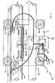
- Figure 1 is a perspective view of an apparatus for supporting a lure according to the invention;
- Figure 2 is a front elevation of the apparatus of Figure 1 of the drawings;
- Figure 3 is a plan view of the apparatus of Figure 2 of the drawings;
- Figure 4 is a side elevation of the apparatus of Figure 1 of the drawings;
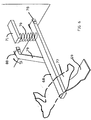
- Figure 5 is a detail of part of a support system for the apparatus of Figure 1 of the drawings; and
- Figure 6 is a perspective and detailed view of a part of the apparatus of Figure 1 of the drawings.
- Referring now to the drawings, there is shown an
apparatus 10 according to the invention which comprises atrolley 50 having asupport element 51, a motor (not shown) mounted in ahousing 54, a first pair ofwheels 55; a second pair ofwheels 56, adrive pulley 57 andidler pulleys support element 51 by means of a pair ofbrackets electrical cable 62 is connected to the motor thefree ends cable 62 are connected to a respectiveelectrical brushes brush brush support member - The
brush support member 52 comprises ahousing 72 having a spring (not shown) which biases aplunger 73 outwardly from the housing there being conventional means (not shown) to retain theplunger 73 in thehousing 72. Essentially, therefore, theplunger 73 is slidably engageable in thehousing 72. The free end of theplunger 73 is pivotally attached to alug 74 to which is fixed fast thebrush 65. Thebrush 65 is electrically isolated from thelug 74. Thehousing 72 is pivotally attached to one end of abrush support member 75 the other end of which is attached to theplate 51. Thebrush support 53 is similarly constructed and supports thebrush 66. - Also attached to the
support element 51, by means ofrespective axles 76, are the pairs ofwheels axle 67 on which is mounted thedrive pulley 57. Thesupport element 51 also has mounted thereon theidler pulleys pulleys wheels pulleys idler pulleys drive pulley 57 forming the apex of the triangle. - The
pulleys pulley 59 is slightly non-coplanar relative to thepulley 57. - Pivotally attached to the
support plate 51 by means of a lug andpin arrangement 78 isfirst arm 68 from which projects askid 69. Thearm 68 has one end of aspring 70 attached thereto the other end of whichspring 70 is attached to asecond arm 71 attached to theplate 51. Further support for thearm 68 is provided by an L-shaped leg member 79 one end of which is welded to or is integral with thearm 68 the other end of whichmember 79 is pivotally attached to theplate 51 by a lug andpin arrangement 80. Also attached to thearm 68 is alure 77. - To use the
apparatus 10, there is installed preferably on the outer perimeter of a greyhound track a series of main frame supports 11 at distances of approximately 2.5m from each other. - Each
support 11 is substantially U-shaped havinglegs arm 14. Theleg 12 is longer than theleg 15 and thus the end of theleg 12 is embedded in aconcrete base 13 located below theground 13a. The end of theleg 15 is located a distance above theground 13a. Mounted on theleg 15 are two nut andbolt arrangements respective rails rails - Mounted on the
leg 12 by means of a nut andbolt arrangement 19a is an L-shaped bracket 19 havinglegs leg 21 supports an electrically insulatingmedium 25 having electricallyconductive strips strip leg 15 and located between therails cable support element 18. Therails shaped bracket 19, thesupport medium 25, thestrips endless facia 100 could be attached to thelegs 15, so as to cover the rails etc. from the general view of the public. - Finally, there is provided a
cable 24. Thecable 24, which would be endless would simply rest on thesupports 18. Thecable 24 would be of the type in which a length of 500 metres would have a weight of about 65kg. - The
apparatus 10 is lifted into position so that thewheels 55 rests on therail 16 and thewheels 56 rest on therail 17. Thecable 24 is engaged with thedrive pulley 57. In engaging thedrive pulley 57, it is important that thecable 24 be in tangential arrangement relative to thepulley 57 at two locations and further that the cable passes virtually around the entire circumference of thepulley 57. Thepulleys pulley 59 does not share the same plane as that of thepulleys cable 24 which connects thepulley 58 with thepulley 57 is not in friction engagement with that part of thecable 24 which connects thepulley 57 with thepulley 59. - The
electric brushes respective strips strips strips - When electricity is applied to the
strips trolley 50 is actuated thereby causing thedrive pulley 57 to rotate. Rotation of thedrive pulley 57 causes thetrolley 50 to move relative to thestationery cable 24 along therails trolley 50 may be controlled by varying the current or voltage applied to thestrips skid 69 is to prevent thelure 77 from being damaged through contact with any undulating ground. Theskid 69 is in contact with the ground and serves to push thearm 68 against the bias of thespring 70. It will be appreciated that thearm 68 projects beyond the plane of the facia and hence thelure 77 if located in front of thefacia 100 will be easily silhouetted against the preferably plain background of thefacia 100. - The advantages of the invention include the fact that when installed in a track having a sand base, little of no damage is caused to the
apparatus 10 by the sand given the relatively simple construction thereof and the lack of movement of thecable 24. By mounting thewheels - The invention is not limited by or to the specific embodiments described which can undergo considerable variation without departing from the scope of the invention.
Claims (8)
- A support apparatus for supporting a lure which apparatus comprises a trolley having wheels for engaging with one or more rails; a drive pulley and two associated idler pulleys; a drive means for the drive pulley; the arrangement being such that when mounted on the or each rail, the drive pulley and the associated idler pulleys are interengageable with an endless stationary cable so that upon actuation of the motor means the trolley moves along the rails relative to the stationary cable.
- A support apparatus as claimed in claim 1 wherein the axis of drive pulley and the axes of idler pulleys are in substantially parallel spaced apart relationship being transverse to the axes of the wheels.
- A support apparatus as claimed in claim 2 wherein the axes of the pulleys provide for the respective apices of a notional triangle.
- A support apparatus as claimed in claim 2 or claim 3 wherein the idler pulleys are substantially co-planar and the drive pulley is non-coplanar relative to the idler pulleys.
- A support apparatus as claimed in any of claims 1-4 which further comprises one or more support rails for enabling the wheels to traverse therealong and means for enabling an electrical connection to be made from the support rail so as to power the motor.
- A support apparatus as claimed in claim 5 which further comprises a plurality of u-shaped support elements each having legs of unequal length for supporting the rail or rails, the longer leg being ground engaging and the shorter leg terminating a distance above the ground, each support having means for enabling the cable to rest thereon when not in engagement with the pulleys.
- A support apparatus as claimed in claim 6 which further comprises a facia mounted on the shorter leg so as to conceal the rails and the trolley from general view, the facia terminating above the ground so that an arm, one end of which is attached to the trolley and the other end having the lure attached thereto, does not, during travel of the trolley, engage with the shorter leg or the facia thereby permitting the lure to be seen against the background of the facia.
- A support apparatus as claimed in claim 7 wherein the arm is pivotally attached to the trolley, biasing means is provided for urging the arm and hence the lure in a ground engaging direction, the lure having a ground engaging skid so that in use, the skid serves to prevent the lure from engaging with the ground which skid traverses the ground including undulating ground which provides a force acting against the biasing means.
Applications Claiming Priority (2)
| Application Number | Priority Date | Filing Date | Title |
|---|---|---|---|
| IE930231 | 1993-03-23 | ||
| IE930231 | 1993-03-23 |
Publications (1)
| Publication Number | Publication Date |
|---|---|
| EP0640366A1 true EP0640366A1 (en) | 1995-03-01 |
Family
ID=11039920
Family Applications (1)
| Application Number | Title | Priority Date | Filing Date |
|---|---|---|---|
| EP94650009A Withdrawn EP0640366A1 (en) | 1993-03-23 | 1994-03-23 | A lure device |
Country Status (1)
| Country | Link |
|---|---|
| EP (1) | EP0640366A1 (en) |
Cited By (1)
| Publication number | Priority date | Publication date | Assignee | Title |
|---|---|---|---|---|
| KR100644349B1 (en) | 2004-01-30 | 2006-11-13 | 김형옥 | track assembly for dog-race |
Citations (6)
| Publication number | Priority date | Publication date | Assignee | Title |
|---|---|---|---|---|
| GB355423A (en) * | 1930-06-25 | 1931-08-27 | Johnston Hill | Improvement in and relating to greyhound racing with dummy hares |
| US1923085A (en) * | 1930-11-08 | 1933-08-22 | Flick Franklin | Portable equipment for coursing parks |
| EP0161437A2 (en) * | 1984-04-13 | 1985-11-21 | Baco AG, Seilbahnen und Aufzüge | Cable crane |
| US4646924A (en) * | 1984-12-27 | 1987-03-03 | Canadian Patents And Development Limited | Mechanical log yarding carriage |
| EP0274555A1 (en) * | 1987-01-15 | 1988-07-20 | Kozo Hirano | Radio-controlled aerial cableway transport system |
| WO1991009762A1 (en) * | 1989-12-29 | 1991-07-11 | Giuseppe Raimo | Cableway transportation |
-
1994
- 1994-03-23 EP EP94650009A patent/EP0640366A1/en not_active Withdrawn
Patent Citations (6)
| Publication number | Priority date | Publication date | Assignee | Title |
|---|---|---|---|---|
| GB355423A (en) * | 1930-06-25 | 1931-08-27 | Johnston Hill | Improvement in and relating to greyhound racing with dummy hares |
| US1923085A (en) * | 1930-11-08 | 1933-08-22 | Flick Franklin | Portable equipment for coursing parks |
| EP0161437A2 (en) * | 1984-04-13 | 1985-11-21 | Baco AG, Seilbahnen und Aufzüge | Cable crane |
| US4646924A (en) * | 1984-12-27 | 1987-03-03 | Canadian Patents And Development Limited | Mechanical log yarding carriage |
| EP0274555A1 (en) * | 1987-01-15 | 1988-07-20 | Kozo Hirano | Radio-controlled aerial cableway transport system |
| WO1991009762A1 (en) * | 1989-12-29 | 1991-07-11 | Giuseppe Raimo | Cableway transportation |
Cited By (1)
| Publication number | Priority date | Publication date | Assignee | Title |
|---|---|---|---|---|
| KR100644349B1 (en) | 2004-01-30 | 2006-11-13 | 김형옥 | track assembly for dog-race |
Similar Documents
| Publication | Publication Date | Title |
|---|---|---|
| SU1727527A3 (en) | Device to lead in three-phase winding of linear motor into inductor | |
| US4763771A (en) | Conveyor installation | |
| US4869030A (en) | Porch adapted for use with a mobile living unit | |
| US5701992A (en) | Sorting equipment | |
| US4691639A (en) | Rail tie plate placing vehicle and method | |
| US3733446A (en) | Guided vehicle power supply system | |
| HUP0401304A2 (en) | Apparatus, systems and methods for levitating and moving objects | |
| FR2548479A1 (en) | METHOD AND DEVICE FOR THE INSTALLATION OF A PREFABRICATED WINDING OF A LINEAR MOTOR | |
| EP1558458B1 (en) | Permanent control device for the grounding of an electric public transport vehicle running on tyres and which is self-guided | |
| EP0640366A1 (en) | A lure device | |
| US20010048845A1 (en) | Barricade apparatus | |
| US3616762A (en) | Overhead conveyor system | |
| FR2552629A1 (en) | DEVICE FOR ASSEMBLING ELECTRIC DISCHARGE OF ANIMALS INTENDED FOR SLAUGHTER | |
| FR2863958B1 (en) | DEVICE FOR GUIDING AND ELECTRICALLY POWERING THE GROUND OF A VEHICLE BY A CHUTE | |
| FR2696985A1 (en) | Electric current supply process for urban electric vehicle supplied from street contact pads - using retractable contact roller collecting current from spaced fixed pads which are energised only when covered by vehicle | |
| US4403760A (en) | Apparatus for raising and lowering an object | |
| US4582192A (en) | Conveyor with twin belt synchronizing mechanism | |
| US2835370A (en) | Article handling apparatus | |
| US3696752A (en) | Conveyor system | |
| CA2446937A1 (en) | Automatic and guided system for transporting people and method for controlling transport modules running in such a system | |
| US3339496A (en) | Apparatus for loading passengers on a ski tow | |
| FR2517649A1 (en) | Programmable cross feed trolley for conveyor - uses friction rollers on ends of sliding beam to transmit drive to conveyor rollers on contact | |
| US1728576A (en) | Animal training and racing apparatus | |
| FR3104119A1 (en) | PUBLIC TRANSPORT SYSTEM | |
| JP3171359B2 (en) | Transfer device |
Legal Events
| Date | Code | Title | Description |
|---|---|---|---|
| PUAI | Public reference made under article 153(3) epc to a published international application that has entered the european phase |
Free format text: ORIGINAL CODE: 0009012 |
|
| AK | Designated contracting states |
Kind code of ref document: A1 Designated state(s): AT BE CH DE DK ES FR GB GR IE IT LI LU MC NL PT SE |
|
| 17P | Request for examination filed |
Effective date: 19950824 |
|
| STAA | Information on the status of an ep patent application or granted ep patent |
Free format text: STATUS: THE APPLICATION IS DEEMED TO BE WITHDRAWN |
|
| 18D | Application deemed to be withdrawn |
Effective date: 19961001 |