EP0639352A1 - Bone treating device - Google Patents
Bone treating device Download PDFInfo
- Publication number
- EP0639352A1 EP0639352A1 EP94113002A EP94113002A EP0639352A1 EP 0639352 A1 EP0639352 A1 EP 0639352A1 EP 94113002 A EP94113002 A EP 94113002A EP 94113002 A EP94113002 A EP 94113002A EP 0639352 A1 EP0639352 A1 EP 0639352A1
- Authority
- EP
- European Patent Office
- Prior art keywords
- nail
- length
- variable
- screws
- longitudinal slot
- Prior art date
- Legal status (The legal status is an assumption and is not a legal conclusion. Google has not performed a legal analysis and makes no representation as to the accuracy of the status listed.)
- Withdrawn
Links
Images

Classifications
-
- A—HUMAN NECESSITIES
- A61—MEDICAL OR VETERINARY SCIENCE; HYGIENE
- A61B—DIAGNOSIS; SURGERY; IDENTIFICATION
- A61B17/00—Surgical instruments, devices or methods, e.g. tourniquets
- A61B17/56—Surgical instruments or methods for treatment of bones or joints; Devices specially adapted therefor
- A61B17/58—Surgical instruments or methods for treatment of bones or joints; Devices specially adapted therefor for osteosynthesis, e.g. bone plates, screws, setting implements or the like
- A61B17/60—Surgical instruments or methods for treatment of bones or joints; Devices specially adapted therefor for osteosynthesis, e.g. bone plates, screws, setting implements or the like for external osteosynthesis, e.g. distractors, contractors
- A61B17/66—Alignment, compression or distraction mechanisms
-
- A—HUMAN NECESSITIES
- A61—MEDICAL OR VETERINARY SCIENCE; HYGIENE
- A61B—DIAGNOSIS; SURGERY; IDENTIFICATION
- A61B17/00—Surgical instruments, devices or methods, e.g. tourniquets
- A61B17/56—Surgical instruments or methods for treatment of bones or joints; Devices specially adapted therefor
- A61B17/58—Surgical instruments or methods for treatment of bones or joints; Devices specially adapted therefor for osteosynthesis, e.g. bone plates, screws, setting implements or the like
- A61B17/68—Internal fixation devices, including fasteners and spinal fixators, even if a part thereof projects from the skin
- A61B17/72—Intramedullary pins, nails or other devices
- A61B17/7216—Intramedullary pins, nails or other devices for bone lengthening or compression
-
- A—HUMAN NECESSITIES
- A61—MEDICAL OR VETERINARY SCIENCE; HYGIENE
- A61B—DIAGNOSIS; SURGERY; IDENTIFICATION
- A61B17/00—Surgical instruments, devices or methods, e.g. tourniquets
- A61B2017/00535—Surgical instruments, devices or methods, e.g. tourniquets pneumatically or hydraulically operated
- A61B2017/00539—Surgical instruments, devices or methods, e.g. tourniquets pneumatically or hydraulically operated hydraulically
-
- A—HUMAN NECESSITIES
- A61—MEDICAL OR VETERINARY SCIENCE; HYGIENE
- A61B—DIAGNOSIS; SURGERY; IDENTIFICATION
- A61B17/00—Surgical instruments, devices or methods, e.g. tourniquets
- A61B2017/00535—Surgical instruments, devices or methods, e.g. tourniquets pneumatically or hydraulically operated
- A61B2017/00544—Surgical instruments, devices or methods, e.g. tourniquets pneumatically or hydraulically operated pneumatically
Definitions
- the invention relates to a device for treating a bone with a nail that can be inserted into it, the central axis of which has openings for receiving screws, bolts or the like.
- Cross pin elements at least one round hole, in particular a pair of round holes, being provided as an opening at one end of the nail.
- Such intramedullary nails with an end point are used in the surgical technique for nailing broken bones.
- the surgeon places an awl or a guide wire in the middle of the fossa trochantrica.
- a ball point of the guidewire is inserted up to the fracture site, then in one of the surgical methods, the channel created in this way for the insertion of the intramedullary nail is milled and the latter hammered in.
- there is a distal locking by means of at least one screw penetrating the intramedullary nail, the two ends of which are fixed in the bone.
- a nail can also be inserted without milling.
- so-called locking screws are preferably used, for example in the case of a tibia at least two screws.
- a puller adapter is screwed onto the proximal end of the intramedullary nail and the latter is driven out with a slotted hammer.
- Intramedullary nails are either - preferably anterior - provided with a slot along their length or have a closed cross section of, for example, 8 mm to 16 mm in diameter, the locking screws have a partial thread with an outside diameter of approximately 4.5 mm.
- a longitudinal slot for receiving at least one bolt or screw or the like which is slidable therein.
- Arranged pin element, and the latter is or the like with the screw / s.
- Pin element / s of the other nail end connected by a length-adjustable adjustment device. The result of this requirement is that the screws passing through the longitudinal slot are guided in it; since they also penetrate the bone or bone cortex - fixed in it - the corresponding part of the bone can be moved as required by the spreading action of the adjusting device.
- the nail is equipped at both ends with at least one round hole - preferably with a pair of round holes - in each of which a screw or the like.
- Pin element for the adjustment device mentioned can be connected, at the same time the nail is designed to be variable in length between the two end regions, preferably as a telescope.
- the nail provided with the longitudinal slot can also be designed to be variable in length, so that the mode of operation of the two embodiments described above can be combined.
- the telescopically adjustable adjustment device is provided at a distance parallel to the nail, since it must be arranged outside the bone to be treated.
- At least one round hole for a pin element - preferably a pair of round holes - is arranged in the proximal end region of the nail and the longitudinal slot in the distal region, in which the nail is advantageously provided with a tip in a manner known per se.
- At least one round hole can also be assigned to the longitudinal slot - preferably a pair of round holes - whereby in one embodiment this round hole lies to the side of the longitudinal slot, in another embodiment in the straight line determined by the longitudinal slot, that is to say preferably in the central nail axis.
- a reverse brake is provided between the two mutually movable sections of the variable-length nail.
- At least one section can be a hollow profile and a rod of the other section can be displaced in a piston-like manner therein.
- both sections can be hollow profiles with a rod which can be relatively moved therein.
- the mentioned reverse brake preferably comprises a toothed strip on a movement partner, with which a stop element of the other sliding partner meshes in such a way that there is an inhibition against the stroke direction of the rod.
- the locking or stop member is preferably designed as a spring tongue, the free end of which abuts against a step surface of the toothed strip mentioned.
- this device a uniform force distribution can be achieved by engaging the thread flanks of the Schanz screws mentioned in the nail and the cortical bone.
- the Schanz screws at the proximal end are exchanged for locking screws.
- the Schanz screws are removed after insertion the locking screws in special holes.
- the distal Schanz screws are inserted on the proximal side of the elongated hole or longitudinal slot and moved in the distal direction when the adjusting device is distracted.
- the locking screw is inserted into a borehole in the distal region, the Schanz screws are removed and the Schanz screws are replaced proximally by locking screws.
- the Schanz screws are anchored in the intramedullary nail and in the cortical bone; the intramedullary nail remains fixed both proximally and distally.
- the load is borne by the adjusting device or the fixator and the Schanz screws in a rigid connection with the intramedullary nail, without bending forces acting on the fixator.
- the Schanz screws are replaced by locking screws.
- the actual extension process is brought about by manual, mechanical force influences from the outside via the adjustment device.
- the forces can also be applied electrically, hydraulically or pneumatically.
- the Schanz screws can also be replaced with locking screws.
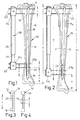
- a metallic nail 12 of constant length b which has been attached with its nail tip 14 to the bone end near the trunk and hammered into its marrow.
- the slightly angled proximal end 16 of the intramedullary nail 12 penetrates two transverse bores 18 at a distance i from one another, and an elongated hole or longitudinal slot 20 of a length t of, for example, 40 to 80 mm runs in the distal nail tip 14 in the central axis M of the intramedullary nail 12.
- 3, 4 further longitudinal bores 19 can be assigned to the longitudinal slot 20 axially or radially.
- the two proximal transverse bores 18 each receive a screw 22 which penetrates them and the tibia 10 and which, in the drawing on the left, sits outside the tibia 10 in a holding head 24 of a cylinder part 26.
- the screws 22, 23 are parallel to each other.
- the lower screws 23, 23p in the drawing pass through the tibia 10 and the longitudinal slot 20, the proximal screw 23p in FIG. 1 abutting the inside of the upper slot end.
- the nail tip 14 is used to guide the screws 23, 23p which move in the longitudinal slot 20 by increasing the effective length of the fixator 28; the distance e between the lower screw 23 and the distal end of the bone remains unchanged. Thanks to this mounting of the thread flanks of the screws 23, 23p in the intramedullary nail 12 and in the bone cortex 11 - the extension region of which is designated 11a in FIG. 2 - a uniform force distribution is produced.
- the screws 22, also referred to as Schanz screws are replaced by so-called locking screws (not shown) which hold the intramedullary nail 12 anchored in the bone.
- the distal nail area - nail tip 14 - is anchored by locking screws which penetrate the bores 19.
- the Schanz screws 23, 23p are also removed from the tibia 10.
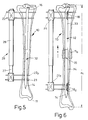
- extension nail 32 which in turn is variable in length. It is divided approximately into the longitudinal center, and the two nail parts 33, 34 thus created are partially hollow for receiving an axial piece 35 connecting them. This enables the telescopic extension of the extension nail 33 when the two nail parts 33, 34 are pulled apart.
- transverse bores 18, 18d are provided for the Schanz screws 22, 23, 23p both in the proximal nail part 33 and in the region of the distal nail tip 14 , ie the extension nail 32 remains fixed proximally and distally.
- the load is borne by the fixator 28 and the Schanz screws 22, 23, 23p in a rigid connection with the extension nail 32. If the intended maximum length a1 of the bone 10 is reached, the screws 22, 23, 23p are - as already described - replaced by locking screws.
- the distal nail part 34 is configured in its upper region as a sleeve 36, into which the rod-like end 38 of the proximal nail part 33 protrudes.
- This rod end 38 is provided with a longitudinal groove 49 in which a spring tongue 42 is fixed axially parallel is.
- Their outwardly curved tongue end 43 interacts with an inner toothed bar 46 molded into the sleeve 36; the lower tongue edge 44 can abut one of the upwardly directed shoulder or step surfaces 48 of the teeth 47 as a stop edge if the rod end 38 tries to slide against the stroke direction x.
- the pairing of step surface 48 / stop surface 44 thus acts as a reverse brake.
- the aforementioned Schanz screws are anchored in it and in the corticalis.
- the intramedullary nail 32 remains fixed proximally and distally.
- the load is borne by the fixator 28 and the Schanz screws in a rigid connection with the intramedullary nail 32, with no bending forces occurring on the fixator 28.
- the Schanz screw is replaced by locking screws, as already mentioned.
Abstract
Description
Die Erfindung betrifft eine Vorrichtung zum Behandeln eines Knochens mit einem in diesen einsetzbaren Nagel, dessen Mittelachse Durchbrüche zur Aufnahme von Schrauben, Bolzen od.dgl. Stiftelementen queren, wobei an einem Ende des Nagels zumindest ein Rundloch, insbesondere ein Paar von Rundlöchern, als Durchbruch vorgesehen ist.The invention relates to a device for treating a bone with a nail that can be inserted into it, the central axis of which has openings for receiving screws, bolts or the like. Cross pin elements, at least one round hole, in particular a pair of round holes, being provided as an opening at one end of the nail.
Derartige Marknägel mit einer endwärtigen Spitze werden in der Operationstechnik zur Nagelung von Knochenbrüchen eingesetzt. Beispielsweise setzt der Operateur bei einem Femurbruch in der Schaftachse eine Ahle an oder einen Führungsdraht in der Mitte der Fossa trochantrica. Eine Kugelspitze des Führungsdrahtes wird bis zur Frakturstelle eingeschoben, dann wird bei einer der Operationsmethoden der so entstandene Kanal zur Einführung des Marknagels aufgefräst und letzterer eingeschlagen. Anschließend erfolgt eine distale Verriegelung mittels wenigstens einer den Marknagel durchsetzenden Schraube, deren beide Enden im Knochen festliegen. Selbstverständlich kann ein Nagel auch ohne Auffräsung eingebracht werden.Such intramedullary nails with an end point are used in the surgical technique for nailing broken bones. For example, in the event of a femur fracture in the shaft axis, the surgeon places an awl or a guide wire in the middle of the fossa trochantrica. A ball point of the guidewire is inserted up to the fracture site, then in one of the surgical methods, the channel created in this way for the insertion of the intramedullary nail is milled and the latter hammered in. Then there is a distal locking by means of at least one screw penetrating the intramedullary nail, the two ends of which are fixed in the bone. Of course, a nail can also be inserted without milling.
Hierzu werden bevorzugt sog. Verriegelungsschrauben eingesetzt, beispielsweise bei einer Tibia zumindest zwei Schrauben.For this purpose, so-called locking screws are preferably used, for example in the case of a tibia at least two screws.
Zur Extraktion des Nagels werden die Schrauben entfernt, ein Ausschlägeradapter auf das proximale Ende des Marknagels geschraubt und letzterer mit einem Schlitzhammer ausgetrieben.To extract the nail, the screws are removed, a puller adapter is screwed onto the proximal end of the intramedullary nail and the latter is driven out with a slotted hammer.
Marknägel sind entweder -- bevorzugt anterior -- der Länge nach mit einem Schlitz versehen oder weisen einen geschlossenen Querschnitt von beispielsweise 8 mm bis 16 mm Durchmesser auf, die Verriegelungsschrauben haben ein Teilgewinde mit einem Außendurchmesser von etwa 4,5 mm.Intramedullary nails are either - preferably anterior - provided with a slot along their length or have a closed cross section of, for example, 8 mm to 16 mm in diameter, the locking screws have a partial thread with an outside diameter of approximately 4.5 mm.
In Kenntnis dieses Standes der Technik hat sich der Erfinder das Ziel gesetzt, eine Vorrichtung der eingangs erwähnten Art so auszugestalten, daß sie für die Verlängerung von Knochen eingesetzt zu werden vermag.Knowing this prior art, the inventor has set himself the goal of designing a device of the type mentioned at the outset in such a way that it can be used for the elongation of bones.
Zur Lösung dieser Aufgabe führt die Lehre des Patentanspruches 1; im anderen Endbereich des Nagels ist ein Längsschlitz zur Aufnahme wenigstens eines darin gleitbaren Bolzens, einer Schraube od.dgl. Stiftelement angeordnet, und letzteres wird mit der/den Schraube/n od.dgl. Stiftelement/en des anderen Nagelendes durch eine längenveränderbare Verstelleinrichtung verbunden. Diese Maßgabe hat zur Folge, daß die den Längsschlitz durchsetzenden Schrauben in diesem geführt werden; da sie zudem den Knochen bzw. die Knochenrinde -- in dieser fixiert -- durchgreifen, kann der entsprechende Teil des Knochens durch die Spreizwirkung der Verstelleinrichtung nach Bedarf verschoben werden.The teaching of claim 1 leads to this object. in the other end region of the nail is a longitudinal slot for receiving at least one bolt or screw or the like which is slidable therein. Arranged pin element, and the latter is or the like with the screw / s. Pin element / s of the other nail end connected by a length-adjustable adjustment device. The result of this requirement is that the screws passing through the longitudinal slot are guided in it; since they also penetrate the bone or bone cortex - fixed in it - the corresponding part of the bone can be moved as required by the spreading action of the adjusting device.
Im Rahmen der Erfindung liegt jedoch auch eine andere Lösung nach dem zweiten unabhängigen Patentanspruch; der Nagel ist an seinen beiden Enden jeweils mit wenigstens einem Rundloch -- bevorzugt mit einem Paar von Rundlöchern -- ausgestattet, in welche jeweils eine Schraube od.dgl. Stiftelement für die erwähnte Verstelleinrichtung angeschlossen werden kann, zugleich ist der Nagel zwischen den beiden Endbereichen längenveränderlich ausgebildet, bevorzugt als Teleskop.However, another solution according to the second independent claim lies within the scope of the invention; the nail is equipped at both ends with at least one round hole - preferably with a pair of round holes - in each of which a screw or the like. Pin element for the adjustment device mentioned can be connected, at the same time the nail is designed to be variable in length between the two end regions, preferably as a telescope.
Bei einer besonderen Ausführung kann auch der mit dem Längsschlitz versehene Nagel in sich längenveränderlich ausgebildet sein, so daß die Wirkungsweise beider oben beschriebener Ausführungsformen kombiniert zu werden vermag.In a special embodiment, the nail provided with the longitudinal slot can also be designed to be variable in length, so that the mode of operation of the two embodiments described above can be combined.
In all diesen Applikatlonsfällen ist die teleskopartig einstellbare Verstelleinrichtung in einem Abstand parallel zum Nagel vorgesehen, da sie außerhalb des zu behandelnden Knochens angeordnet sein muß.In all of these application cases, the telescopically adjustable adjustment device is provided at a distance parallel to the nail, since it must be arranged outside the bone to be treated.
Weitere besondere Ausgestaltungen des Erfindungsgegenstandes sind den abhängigen Patentansprüchen zu entnehmen.Further special configurations of the subject matter of the invention can be found in the dependent claims.
So ist zumindest ein Rundloch für ein Stiftelement -- bevorzugt ein Paar von Rundlöchern -- im proximalen Endbereich des Nagels angeordnet und der Längsschlitz im distalen Bereich, in welchem der Nagel in an sich bekannter Weise vorteilhafterweise mit einer Spitze versehen ist.At least one round hole for a pin element - preferably a pair of round holes - is arranged in the proximal end region of the nail and the longitudinal slot in the distal region, in which the nail is advantageously provided with a tip in a manner known per se.
Auch kann dem Längsschlitz zumindest ein Rundloch zugeordnet sein -- bevorzugt ein Paar von Rundlöchern --, wobei in einer Ausführung dieses Rundloch seitlich des Längsschlitzes liegt, bei einer anderen Ausführung in der vom Längsschlitz bestimmten Geraden, also bevorzugt in der Nagelmittelachse.At least one round hole can also be assigned to the longitudinal slot - preferably a pair of round holes - whereby in one embodiment this round hole lies to the side of the longitudinal slot, in another embodiment in the straight line determined by the longitudinal slot, that is to say preferably in the central nail axis.
Nach einem weiteren Merkmal der Erfindung ist zwischen den beiden gegeneinander bewegbaren Abschnitten des längenveränderlichen Nagels eine Rücklaufbremse vorgesehen.According to a further feature of the invention, a reverse brake is provided between the two mutually movable sections of the variable-length nail.
Erfindungsgemäß kann zumindest ein Abschnitt ein Hohlprofil und in diesem ein Stab des anderen Abschnittes kolbenartig verschiebbar sein. Jedoch ist es auch möglich, daß beide Abschnitte Hohlprofile mit in ihnen relativ bewegbarem Stab sind. In diesem Falle umfaßt die erwähnte Rücklaufbremse bevorzugt eine Zahnleiste an einem Bewegungspartner, mit der ein Anschlagelement des anderen Gleitpartners so kämmt, daß eine Hemmung gegen die Hubrichtung des Stabes entsteht. Das Rast- oder Anschlagorgan wird bevorzugt als Federzunge ausgebildet, deren freies Ende gegen eine Stufenfläche der erwähnten Zahnleiste anschlägt.According to the invention, at least one section can be a hollow profile and a rod of the other section can be displaced in a piston-like manner therein. However, it is also possible for both sections to be hollow profiles with a rod which can be relatively moved therein. In this case, the mentioned reverse brake preferably comprises a toothed strip on a movement partner, with which a stop element of the other sliding partner meshes in such a way that there is an inhibition against the stroke direction of the rod. The locking or stop member is preferably designed as a spring tongue, the free end of which abuts against a step surface of the toothed strip mentioned.
Dank dieser Vorrichtung kann durch das Eingreifen der Gewindeflanken der erwähnten Schanz'schen Schrauben im Nagel und der Cortikalis eine gleichmäßige Kraftverteilung erzielt werden. Beim Erreichen der vorgegebenen Maximallänge werden die Schanz'schen Schrauben am proximalen Ende gegen Verriegelungsschrauben ausgestauscht. Am distalen Ende erfolgt das Herausnehmen der Schanz'schen Schrauben nach dem Einbringen der Verriegelungsschrauben in besondere Bohrungen. Die distalen Schanz'schen Schrauben werden an der proximalen Seite des Langloches oder Längsschlitzes eingebracht und mit der Distrahierung der Verstelleinrichtung in distaler Richtung verschoben.Thanks to this device, a uniform force distribution can be achieved by engaging the thread flanks of the Schanz screws mentioned in the nail and the cortical bone. When the specified maximum length is reached, the Schanz screws at the proximal end are exchanged for locking screws. At the distal end, the Schanz screws are removed after insertion the locking screws in special holes. The distal Schanz screws are inserted on the proximal side of the elongated hole or longitudinal slot and moved in the distal direction when the adjusting device is distracted.
Nach dem Erreichen der maximal gewünschten Verlängerung wird die Verriegelungsschraube im distalen Bereich in ein Bohrloch eingesetzt, die Schanz'schen Schrauben entfernt und dann noch proximal die Schanz'schen Schrauben durch Verrlegelungsschrauben ersetzt.After the maximum desired extension has been reached, the locking screw is inserted into a borehole in the distal region, the Schanz screws are removed and the Schanz screws are replaced proximally by locking screws.
Die soeben beschriebene Vorgehensweise ist für den nicht verlängerbaren Nagel gedacht; bei dem längenveränderlichen Nagel nach dem zweiten unabhängigen Patentanspruch werden die Schanz'schen Schrauben im Marknagel und in der Cortikalis verankert; der Marknagel bleibt proximal und distal gleichermaßen fixiert. In diesem Falle wird die Belastung von der Verstelleinrichtung bzw. dem Fixateur und den Schanz'schen Schrauben in starrer Verbindung mit dem Marknagel getragen, ohne daß auf den Fixateur Biegekräfte einwirken würden. Beim Erreichen der maximal gewünschten Länge werden die Schanz'schen Schrauben durch Verriegelungsschrauben ersetzt.The procedure just described is intended for the non-renewable nail; in the variable-length nail according to the second independent claim, the Schanz screws are anchored in the intramedullary nail and in the cortical bone; the intramedullary nail remains fixed both proximally and distally. In this case, the load is borne by the adjusting device or the fixator and the Schanz screws in a rigid connection with the intramedullary nail, without bending forces acting on the fixator. When the maximum desired length is reached, the Schanz screws are replaced by locking screws.
Durch die Verbindung der Schanz'schen Schrauben mit dem Marknagel treten hier wesentlich geringere Biegekräfte bezüglich der Verstelleinrichtung auf, ohne daß sich die auf die Bohrungen oder Rundlöcher auswirkenden Kräfte durch die Cortikalis wesentlich verändern würden.By connecting the Schanz screws with the intramedullary nail, considerably lower bending forces occur with respect to the adjusting device, without the forces acting on the bores or round holes being changed significantly by the cortical bone.
Der eigentliche Verlängerungsvorgang wird durch manuelle, mechanische Krafteinflüsse über die Verstelleinrichtung von außen her bewirkt. Im Rahmen der Erfindung können die Kräfte auch auf elektrischem, hydraulischem oder pneumatischem Wege erfolgen.The actual extension process is brought about by manual, mechanical force influences from the outside via the adjustment device. In the context of the invention, the forces can also be applied electrically, hydraulically or pneumatically.
Ist die gewünschte Verlängerung erfolgt, können auch hier die Schanz'schen Schrauben durch Verriegelungsschrauben ersetzt werden.Once the desired extension has been made, the Schanz screws can also be replaced with locking screws.
Weitere Vorteile, Merkmale und Einzelheiten der Erfindung ergeben sich aus der nachfolgenden Beschreibung bevorzugter Ausführungsbeispiele sowie anhand der Zeichnung; diese zeigt in
- Fig. 1:
- eine Seitenansicht einer Vorrichtung zur axialen Dehnung eines Unterschenkelknochens mit einem intraossären Nagel;
- Fig. 2:
- die Vorrichtung nach Fig. 1 in anderer Betriebsstellung;
- Fig. 3, 4:
- unterschiedliche Details weiterer Ausführungen der Vorrichtung;
- Fig. 5, 6:
- den Fig. 1, 2 entsprechende Wiedergaben einer anderen erfindungsgemäßen Vorrichtung mit längenveränderlichem Nagel;
- Fig. 7:
- die Seitenansicht eines vergrößerten Abschnitts eines längenveränderlichen Nagels;
- Fig. 8:
- ein teilweise geschnittener längenveränderlicher Nagel;
- Fig. 9:
- den vergrößerten Querschnitt durch den Nagel, geschnitten gemäß Linie IX-IX in Fig. 10;
- Fig. 10:
- den vergrößerten Ausschnitt aus Fig. 8 nach deren Feld X;
- Fig. 11,12:
- den Fig. 1, 2 entsprechende schematisierte Darstellungen einer Vorrichtung zur Dehnung eines Oberschenkelknochens oder Femur.
- Fig. 1:
- a side view of a device for the axial expansion of a lower leg bone with an intraosseous nail;
- Fig. 2:
- the device of Figure 1 in a different operating position.
- 3, 4:
- different details of further versions of the device;
- 5, 6:
- 1, 2 corresponding reproductions of another device according to the invention with variable-length nail;
- Fig. 7:
- the side view of an enlarged portion of a variable-length nail;
- Fig. 8:
- a partially cut variable-length nail;
- Fig. 9:
- the enlarged cross section through the nail, cut along line IX-IX in Fig. 10;
- Fig. 10:
- the enlarged section of Figure 8 after their field X;
- Fig. 11.12:
- 1, 2 corresponding schematic representations of a device for stretching a femur or femur.
In einem durch die Kontur 10 angedeuteten Unterschenkelknochen der Länge a verläuft ein metallischer Nagel 12 konstanter Länge b, welcher mit seiner Nagelspitze 14 am rumpfnahen Knochenende angesetzt und in dessen Mark eingeschlagen worden ist. Das leicht abgewinkelte proximale Ende 16 des Marknagels 12 durchsetzen in einem Abstand i zueinander zwei Querbohrungen 18, und in der distalen Nagelspitze 14 verläuft in der Mittelachse M des Marknagels 12 ein Langloch oder Längsschlitz 20 einer Länge t von beispielsweise 40 bis 80 mm. Gemäß Fig. 3, 4 können dem Längsschlitz 20 axial oder radial weitere Querbohrungen 19 zugeordnet sein.In a lower leg bone of length a indicated by the
Die beiden proximalen Querbohrungen 18 nehmen jeweils eine sie und die Tibia 10 durchsetzende Schraube 22 auf, die -- in der Zeichnung links -- außerhalb der Tibia 10 in einem Haltekopf 24 eines Zylinderteiles 26 sitzt. In diesem lagert teleskopartig verschieblich ein Kolbenprofil 27, das einen Haltekopf 24t für zwei andere Schrauben 23 trägt sowie mit dem Zylinderteil 26 eine/n längenveränderliche/n Verstelleinrichtung bzw. Fixateur 28 bildet. Die Schrauben 22, 23 stehen zueinander parallel.The two proximal transverse bores 18 each receive a
Die in der Zeichnung unteren Schrauben 23,23p durchgreifen die Tibia 10 sowie den Längsschlitz 20, wobei die hier proximale Schraube 23p in Fig. 1 dem oberen Schlitzende innenseitig anliegt.The lower screws 23, 23p in the drawing pass through the
Die Nagelspitze 14 dient zur Führung der -- durch Erhöhung der wirksamen Länge des Fixateurs 28 -- im Längsschlitz 20 wandernden Schrauben 23, 23p; der Abstand e der unteren Schraube 23 zum distalen Knochenende bleibt dabei unverändert. Dank dieser Lagerung der Gewindeflanken der Schrauben 23, 23p im Marknagel 12 sowie in der Knochenrinde 11 -- deren Verlängerungsbereich in Fig. 2 mit 11a bezeichnet ist -- entsteht eine gleichmäßige Kraftverteilung.The
Ist die maximale Länge a1 der Tibia 10 erreicht, werden die auch als Schanz'sche Schrauben bezeichneten Schrauben 22 durch -- nicht dargestellte -- sog. Verriegelungsschrauben ersetzt, welche den Marknagel 12 im Knochen verankert halten. Die Verankerung des distalen Nagelbereiches -- Nagelspitze 14 -- erfolgt durch Verriegelungsschrauben, welche die Bohrungen 19 durchsetzen. Dann werden die Schanz'schen Schrauben 23, 23p ebenfalls der Tibia 10 entnommen.Once the maximum length a1 of the
Die Fig. 5 und 6 zeigen einen Verlängerungsnagel 32, der seinerseits längenveränderlich ausgebildet ist. Er ist etwa in Längsmitte unterteilt, und die beiden so entstehenden Nagelteile 33, 34 sind zur Aufnahme eines sie verbindenden Axialstücks 35 teilweise hohl. Dies ermöglicht die teleskopartige Verlängerung des Verlängerungsnagels 33 beim Auseinanderziehen der beiden Nagelteile 33, 34. Bei dieser Ausführung sind sowohl im proximalen Nagelteil 33 als auch im Bereich der distalen Nagelspitze 14 Querbohrungen 18, 18d für die Schanz'schen Schrauben 22, 23, 23p vorgesehen, d.h. der Verlängerungsnagel 32 bleibt durch diese proximal und distal fixiert.5 and 6 show an
Hier wird die Belastung vom Fixateur 28 und den Schanz'schen Schrauben 22, 23, 23p in starrer Verbindung mit dem Verlängerungsnagel 32 getragen. Ist die vorgesehene maximale Länge a1 des Knochens 10 erreicht, werden -- wie bereits geschildert -- auch hier die Schrauben 22, 23, 23p durch Verriegelungsschrauben ersetzt.Here the load is borne by the
Beim Ausführungsbeispiel der Fig. 7, 8 ist der distale Nagelteil 34 in seinem oberen Bereich als Hülse 36 ausgestaltet, in die das stabartige Ende 38 des proximalen Nagelteils 33 einragt. Dieses Stabende 38 ist mit einer Längsnut 49 versehen, in welcher achsparallel eine Federzunge 42 festgelegt ist. Deren nach außen gekrümmtes Zungenende 43 wirkt mit einer in die Hülse 36 eingeformten inneren Zahnleiste 46 zusammen; die untere Zungenkante 44 kann an jeweils einer der nach oben gerichteten Schulter- oder Stufenflächen 48 der Zähne 47 als Anschlagkante anschlagen, wenn das Stabende 38 gegen die Hubrichtung x zu gleiten trachtet. Die Paarung Stufenfläche 48 / Anschlagfläche 44 wirkt somit als Rücklaufbremse.7, 8, the
Die Fig. 11, 12 sollen den Einsatz des Marknagels 12 bei einem Oberschenkelknochen 50 veranschaulichen.11, 12 are intended to illustrate the use of the
Bei Einsatz des längenveränderlichen Marknagels 32 werden die erwähnten Schanz'schen Schrauben in ihm und in der Corticalis verankert. Der Marknagel 32 bleibt proximal sowie distal fixiert. Dabei wird die Belastung vom Fixateur 28 und den Schanz'schen Schrauben in starrer Verbindung mit dem Marknagel 32 getragen, wobei am Fixateur 28 keine Biegekräfte auftreten. Ist die gewünschte Knochenlänge erreicht, werden -- wie bereits erwähnt -- die Schanz'schen Schraube durch Verriegelungsschrauben ersetzt.When using the variable-
Durch die Verbindung der Schanz'schen Schrauben mit dem Marknagel 32 treten wesentlich geringere Biegekräfte auf den Verlängerungsapparat oder Fixateur 28 auf, und die Kräfte auf die Rundlöcher durch die Cortikalis müßten annähern gleich sein.By connecting the Schanz screws with the
Die eigentliche Verbindung erfolgt durch manuelle, mechanische Krafteinflüsse über den Fixateur 28 außen, wobei die Kräfte auch elektrisch, hydraulisch oder pneumatisch erzeugt werden können.The actual connection is made by manual, mechanical force influences via the
Claims (10)
dadurch gekennzeichnet,
daß im anderen Endbereich des Nagels (12, 32) ein Längsschlitz (20) zur Aufnahme wenigstens einer darin gleitbaren Schraube (23,23b) eines Bolzens od.dgl. Stiftelement angeordnet ist und diese/s mit der/den Schraube/n (22) od.dgl. Stiftelement/en des anderen Nagelendes durch eine längenveränderbare Verstelleinrichtung (26) verbunden ist.Device for treating a bone with a nail that can be inserted into it, the central axis of which has openings for receiving screws, bolts or the like. Cross pin elements, at least one round hole, in particular a pair of round holes, being provided as an opening / openings at one end of the nail,
characterized,
that in the other end region of the nail (12, 32) has a longitudinal slot (20) for receiving at least one screw (23, 23b) of a bolt or the like which is slidable therein. Pin element is arranged and this / s with the screw (s) (22) or the like. Pin element / s of the other nail end is connected by a length-adjustable adjustment device (26).
Applications Claiming Priority (2)
| Application Number | Priority Date | Filing Date | Title |
|---|---|---|---|
| DE4328015 | 1993-08-20 | ||
| DE19934328015 DE4328015A1 (en) | 1993-08-20 | 1993-08-20 | Device for treating bones |
Publications (1)
| Publication Number | Publication Date |
|---|---|
| EP0639352A1 true EP0639352A1 (en) | 1995-02-22 |
Family
ID=6495623
Family Applications (1)
| Application Number | Title | Priority Date | Filing Date |
|---|---|---|---|
| EP94113002A Withdrawn EP0639352A1 (en) | 1993-08-20 | 1994-08-19 | Bone treating device |
Country Status (2)
| Country | Link |
|---|---|
| EP (1) | EP0639352A1 (en) |
| DE (1) | DE4328015A1 (en) |
Cited By (19)
| Publication number | Priority date | Publication date | Assignee | Title |
|---|---|---|---|---|
| EP0696441A3 (en) * | 1994-08-10 | 1996-04-03 | Howmedica Gmbh | Means for the stabilization of long bones, especially for the osteotomy |
| WO1997015176A2 (en) * | 1995-10-21 | 1997-05-01 | Dietmar Pennig | Intramedullary cavity nail for femur elongation |
| WO2002007620A3 (en) * | 2000-07-17 | 2002-04-25 | Davila Jorge P Flores | Device and method for bone fixation, compression and distraction |
| EP1350479A3 (en) * | 2002-03-28 | 2004-10-06 | Depuy Orthopaedics, Inc. | Fastener and targeting device for an intra-medullary nail |
| WO2013176632A1 (en) * | 2012-05-23 | 2013-11-28 | Antolic Dr Vane | Modular side device with an intramedullary nail for guiding a bone during its lengthening |
| WO2014039205A1 (en) * | 2012-09-04 | 2014-03-13 | Imds Corporation | External fixation |
| CN105476701A (en) * | 2015-12-14 | 2016-04-13 | 重庆医科大学附属永川医院 | Bone transport apparatus for treatment of large segmental defect of femur |
| CN105476702A (en) * | 2015-12-14 | 2016-04-13 | 重庆医科大学附属永川医院 | Bone transport apparatus for treatment of large segmental defect of humerus |
| JP2016528993A (en) * | 2014-03-14 | 2016-09-23 | ライト メディカル テクノロジー インコーポレイテッドWright Medical Technology, Inc. | Orthopedic compression / distraction device |
| CN106859757A (en) * | 2015-12-14 | 2017-06-20 | 重庆医科大学附属永川医院 | A kind of bone Handling device for shin bone large segmental bone defect |
| US9770272B2 (en) | 2012-12-12 | 2017-09-26 | Wright Medical Technology, Inc. | Orthopedic compression/distraction device |
| WO2017203097A1 (en) * | 2016-05-27 | 2017-11-30 | Synoste Oy | An intra-corporal telescopic osteodistraction device, an extra-corporal force producing device, a method for bone lengthening and a bone lengthening arrangement |
| US9924969B2 (en) | 2012-09-04 | 2018-03-27 | Zimmer, Inc. | External fixation |
| US9962187B2 (en) | 2014-08-11 | 2018-05-08 | Zimmer, Inc. | External fixation |
| CN105877830B (en) * | 2015-12-14 | 2018-07-06 | 重庆医科大学附属永川医院 | A kind of bone handling device for large segmental bone defect |
| EP3808293A1 (en) * | 2019-10-17 | 2021-04-21 | Globus Medical, Inc. | Proximal humeral stabilization systems and methods thereof |
| US11134988B2 (en) | 2015-06-17 | 2021-10-05 | Zimmer, Inc. | Ankle fixation system |
| US11202663B2 (en) | 2019-02-13 | 2021-12-21 | Globus Medical, Inc. | Proximal humeral stabilization systems and methods thereof |
| EP3820389A4 (en) * | 2018-07-09 | 2022-03-23 | Tobb Ekonomi Ve Teknoloji Universitesi | An external fixator having an alignment device |
Citations (3)
| Publication number | Priority date | Publication date | Assignee | Title |
|---|---|---|---|---|
| US2391537A (en) * | 1943-09-27 | 1945-12-25 | Anderson Roger | Ambulatory rotating reduction and fixation splint |
| DE2713837B1 (en) * | 1977-03-25 | 1978-03-02 | Westerhoff Erhard | Drive device for a distraction device |
| DE3921972A1 (en) * | 1989-07-04 | 1991-01-17 | Rainer Dr Baumgart | MARKING NAIL |
-
1993
- 1993-08-20 DE DE19934328015 patent/DE4328015A1/en not_active Withdrawn
-
1994
- 1994-08-19 EP EP94113002A patent/EP0639352A1/en not_active Withdrawn
Patent Citations (3)
| Publication number | Priority date | Publication date | Assignee | Title |
|---|---|---|---|---|
| US2391537A (en) * | 1943-09-27 | 1945-12-25 | Anderson Roger | Ambulatory rotating reduction and fixation splint |
| DE2713837B1 (en) * | 1977-03-25 | 1978-03-02 | Westerhoff Erhard | Drive device for a distraction device |
| DE3921972A1 (en) * | 1989-07-04 | 1991-01-17 | Rainer Dr Baumgart | MARKING NAIL |
Cited By (34)
| Publication number | Priority date | Publication date | Assignee | Title |
|---|---|---|---|---|
| EP0696441A3 (en) * | 1994-08-10 | 1996-04-03 | Howmedica Gmbh | Means for the stabilization of long bones, especially for the osteotomy |
| WO1997015176A2 (en) * | 1995-10-21 | 1997-05-01 | Dietmar Pennig | Intramedullary cavity nail for femur elongation |
| WO1997015176A3 (en) * | 1995-10-21 | 1997-06-12 | Dietmar Pennig | Intramedullary cavity nail for femur elongation |
| WO2002007620A3 (en) * | 2000-07-17 | 2002-04-25 | Davila Jorge P Flores | Device and method for bone fixation, compression and distraction |
| EP1350479A3 (en) * | 2002-03-28 | 2004-10-06 | Depuy Orthopaedics, Inc. | Fastener and targeting device for an intra-medullary nail |
| AU2003203216B2 (en) * | 2002-03-28 | 2008-10-09 | Depuy Orthopaedics, Inc. | Bone fastener targeting and compression/distraction device for an intramedullary nail and method of use |
| WO2013176632A1 (en) * | 2012-05-23 | 2013-11-28 | Antolic Dr Vane | Modular side device with an intramedullary nail for guiding a bone during its lengthening |
| CN104619276A (en) * | 2012-09-04 | 2015-05-13 | 捷迈有限公司 | External fixation |
| US10010348B2 (en) | 2012-09-04 | 2018-07-03 | Zimmer, Inc. | External fixation |
| US9301782B2 (en) | 2012-09-04 | 2016-04-05 | Zimmer, Inc. | External fixation |
| US10905469B2 (en) | 2012-09-04 | 2021-02-02 | Zimmer, Inc. | External fixation |
| CN104619276B (en) * | 2012-09-04 | 2016-08-10 | 捷迈有限公司 | External fixator |
| WO2014039205A1 (en) * | 2012-09-04 | 2014-03-13 | Imds Corporation | External fixation |
| US10433873B2 (en) | 2012-09-04 | 2019-10-08 | Zimmer, Inc. | External fixation |
| US9924969B2 (en) | 2012-09-04 | 2018-03-27 | Zimmer, Inc. | External fixation |
| US10631900B2 (en) | 2012-12-12 | 2020-04-28 | Wright Medical Technology, Inc. | Orthopedic compression/distraction device |
| US9770272B2 (en) | 2012-12-12 | 2017-09-26 | Wright Medical Technology, Inc. | Orthopedic compression/distraction device |
| JP2016528993A (en) * | 2014-03-14 | 2016-09-23 | ライト メディカル テクノロジー インコーポレイテッドWright Medical Technology, Inc. | Orthopedic compression / distraction device |
| US10543019B2 (en) | 2014-08-11 | 2020-01-28 | Zimmer, Inc. | External fixation |
| US9962187B2 (en) | 2014-08-11 | 2018-05-08 | Zimmer, Inc. | External fixation |
| US11134988B2 (en) | 2015-06-17 | 2021-10-05 | Zimmer, Inc. | Ankle fixation system |
| CN105476702A (en) * | 2015-12-14 | 2016-04-13 | 重庆医科大学附属永川医院 | Bone transport apparatus for treatment of large segmental defect of humerus |
| CN106859757A (en) * | 2015-12-14 | 2017-06-20 | 重庆医科大学附属永川医院 | A kind of bone Handling device for shin bone large segmental bone defect |
| CN105877830B (en) * | 2015-12-14 | 2018-07-06 | 重庆医科大学附属永川医院 | A kind of bone handling device for large segmental bone defect |
| CN105476701A (en) * | 2015-12-14 | 2016-04-13 | 重庆医科大学附属永川医院 | Bone transport apparatus for treatment of large segmental defect of femur |
| CN106859757B (en) * | 2015-12-14 | 2018-07-06 | 重庆医科大学附属永川医院 | A kind of bone handling device for shin bone large segmental bone defect |
| CN109195539A (en) * | 2016-05-27 | 2019-01-11 | 希努斯帝有限公司 | Internal telescopic bone distraction apparatus, external force generating apparatus, Limb lengthening method and Limb lengthening arrangement |
| WO2017203097A1 (en) * | 2016-05-27 | 2017-11-30 | Synoste Oy | An intra-corporal telescopic osteodistraction device, an extra-corporal force producing device, a method for bone lengthening and a bone lengthening arrangement |
| US11160588B2 (en) | 2016-05-27 | 2021-11-02 | Bala Sundararajan | System for stabilizing or lengthening bone |
| CN109195539B (en) * | 2016-05-27 | 2022-03-01 | 希努斯帝有限公司 | In vivo retractable bone distraction device, in vitro force generating device, bone lengthening method and bone lengthening arrangement |
| EP3820389A4 (en) * | 2018-07-09 | 2022-03-23 | Tobb Ekonomi Ve Teknoloji Universitesi | An external fixator having an alignment device |
| US11202663B2 (en) | 2019-02-13 | 2021-12-21 | Globus Medical, Inc. | Proximal humeral stabilization systems and methods thereof |
| US11259848B2 (en) | 2019-02-13 | 2022-03-01 | Globus Medical, Inc. | Proximal humeral stabilization systems and methods thereof |
| EP3808293A1 (en) * | 2019-10-17 | 2021-04-21 | Globus Medical, Inc. | Proximal humeral stabilization systems and methods thereof |
Also Published As
| Publication number | Publication date |
|---|---|
| DE4328015A1 (en) | 1995-02-23 |
Similar Documents
| Publication | Publication Date | Title |
|---|---|---|
| EP0639352A1 (en) | Bone treating device | |
| DE60014042T2 (en) | Axial external fixator | |
| EP1761182B1 (en) | Surgical nail | |
| DE3541597C2 (en) | ||
| EP2263584B1 (en) | Intramedullary nail with locking screw | |
| EP2347724B1 (en) | Tensioning device for surgical elements | |
| EP0709072B1 (en) | Device for positioning a hole in a bone | |
| EP0736286A2 (en) | Osteosynthetic device for treating subtrochanteric and pertrochanteric fractures and fractures of the neck of the femur | |
| WO2000067652A2 (en) | Implant for operative treatment of femoral neck fractures and the like | |
| EP1830727B1 (en) | Intramedullary nail | |
| EP1415604B1 (en) | Bone fixationsystem | |
| DE10301444A1 (en) | Intramedullary nail, device for inserting a screw therein, and associated procedure | |
| WO2005037116A1 (en) | Intramedullary nail | |
| EP1648321A1 (en) | Surgical nail | |
| EP2468216B1 (en) | Implantable prosthesis for replacing human hip or knee joints and the adjoining bone sections | |
| DE2705154A1 (en) | BONE MARROW NAIL AND TARGET DEVICE FOR ITS ANCHORING IN THE MARULAR CANAL | |
| DE2246274A1 (en) | DEVICE FOR TREATMENT OF BROKEN TUBE BONES BY AXIAL PRESSURE OSTEOSYNTHESIS | |
| EP0715832B1 (en) | Intramedullary nail for hip compression | |
| EP1455662B1 (en) | Targeting device for a fracture pin | |
| EP1572018B1 (en) | Fracture pin | |
| EP2258290B1 (en) | Humeral nail for humerus fractures | |
| DE2542263A1 (en) | Osteo synthetic pin for bone fractures - has slotted ends which are expanded by screwed spindle | |
| EP1679044B1 (en) | Set for creation of an implant for osteosynthesis | |
| DE102007029090A1 (en) | Device for osteosynthesis, particularly bone fracture near joint, has pin for implantation into abarticular bone, and proximal longitudinal ring element provided for implantation into bone fragment near joint | |
| DE19731879C2 (en) | Intramedullary splint system for long bones |
Legal Events
| Date | Code | Title | Description |
|---|---|---|---|
| PUAI | Public reference made under article 153(3) epc to a published international application that has entered the european phase |
Free format text: ORIGINAL CODE: 0009012 |
|
| AK | Designated contracting states |
Kind code of ref document: A1 Designated state(s): AT BE CH DE DK ES FR GB GR IE IT LI LU MC NL PT SE |
|
| RAX | Requested extension states of the european patent have changed |
Free format text: SI |
|
| 17P | Request for examination filed |
Effective date: 19950310 |
|
| STAA | Information on the status of an ep patent application or granted ep patent |
Free format text: STATUS: THE APPLICATION IS DEEMED TO BE WITHDRAWN |
|
| 18D | Application deemed to be withdrawn |
Effective date: 19990302 |
|
| R18D | Application deemed to be withdrawn (corrected) |
Effective date: 19990301 |