EP0638257B1 - Holding device for rods, tubes and the like - Google Patents
Holding device for rods, tubes and the like Download PDFInfo
- Publication number
- EP0638257B1 EP0638257B1 EP94111033A EP94111033A EP0638257B1 EP 0638257 B1 EP0638257 B1 EP 0638257B1 EP 94111033 A EP94111033 A EP 94111033A EP 94111033 A EP94111033 A EP 94111033A EP 0638257 B1 EP0638257 B1 EP 0638257B1
- Authority
- EP
- European Patent Office
- Prior art keywords
- holding device
- receiving ring
- bore
- ring
- flanges
- Prior art date
- Legal status (The legal status is an assumption and is not a legal conclusion. Google has not performed a legal analysis and makes no representation as to the accuracy of the status listed.)
- Expired - Lifetime
Links
- 230000002035 prolonged effect Effects 0.000 claims 1
- 230000014759 maintenance of location Effects 0.000 abstract 1
- 210000002414 leg Anatomy 0.000 description 17
- 238000011161 development Methods 0.000 description 2
- 230000018109 developmental process Effects 0.000 description 2
- 238000004512 die casting Methods 0.000 description 1
- 238000006073 displacement reaction Methods 0.000 description 1
- 210000001061 forehead Anatomy 0.000 description 1
- 210000003128 head Anatomy 0.000 description 1
- 238000004519 manufacturing process Methods 0.000 description 1
- 238000000034 method Methods 0.000 description 1
- 239000002689 soil Substances 0.000 description 1
- 210000000689 upper leg Anatomy 0.000 description 1
Images

Classifications
-
- A—HUMAN NECESSITIES
- A45—HAND OR TRAVELLING ARTICLES
- A45B—WALKING STICKS; UMBRELLAS; LADIES' OR LIKE FANS
- A45B11/00—Umbrellas characterised by their shape or attachment
-
- A—HUMAN NECESSITIES
- A47—FURNITURE; DOMESTIC ARTICLES OR APPLIANCES; COFFEE MILLS; SPICE MILLS; SUCTION CLEANERS IN GENERAL
- A47B—TABLES; DESKS; OFFICE FURNITURE; CABINETS; DRAWERS; GENERAL DETAILS OF FURNITURE
- A47B37/00—Tables adapted for other particular purposes
- A47B37/04—Tables specially adapted for use in the garden or otherwise in the open air, e.g. with means for holding umbrellas or umbrella-like sunshades
-
- F—MECHANICAL ENGINEERING; LIGHTING; HEATING; WEAPONS; BLASTING
- F16—ENGINEERING ELEMENTS AND UNITS; GENERAL MEASURES FOR PRODUCING AND MAINTAINING EFFECTIVE FUNCTIONING OF MACHINES OR INSTALLATIONS; THERMAL INSULATION IN GENERAL
- F16M—FRAMES, CASINGS OR BEDS OF ENGINES, MACHINES OR APPARATUS, NOT SPECIFIC TO ENGINES, MACHINES OR APPARATUS PROVIDED FOR ELSEWHERE; STANDS; SUPPORTS
- F16M13/00—Other supports for positioning apparatus or articles; Means for steadying hand-held apparatus or articles
- F16M13/02—Other supports for positioning apparatus or articles; Means for steadying hand-held apparatus or articles for supporting on, or attaching to, an object, e.g. tree, gate, window-frame, cycle
- F16M13/022—Other supports for positioning apparatus or articles; Means for steadying hand-held apparatus or articles for supporting on, or attaching to, an object, e.g. tree, gate, window-frame, cycle repositionable
-
- A—HUMAN NECESSITIES
- A47—FURNITURE; DOMESTIC ARTICLES OR APPLIANCES; COFFEE MILLS; SPICE MILLS; SUCTION CLEANERS IN GENERAL
- A47B—TABLES; DESKS; OFFICE FURNITURE; CABINETS; DRAWERS; GENERAL DETAILS OF FURNITURE
- A47B2220/00—General furniture construction, e.g. fittings
- A47B2220/0002—Adjustable furniture construction
- A47B2220/0008—Table or tray, height adjustable on parasol pole
Definitions
- the invention relates to a holding device for rods, pipes or the like, especially for Parasols, according to the preamble of claim 1.
- a holding device of this type has been around for years known, see e.g. DE-U-8 712 448, DE-A-3 619 467; it is used in hardware stores or in Connection with garden and leisure furniture in Specialty shops offered.
- it consists of a U-shaped bracket element to be placed on a Edge of the table, being on the lower leg in one Threaded hole a locking screw is mounted.
- On the vertical web of the A ring is formed on the bracket element, which in a Threaded hole in the wall approximately radial contains standing, manually operated pressure screw.
- the known one-piece holding device is except for a use in the sense described above for other types of support for rods or tubes not suitable. Such is a holding device for example, cannot be used when holding a vertical bar no table top, but a vertical wall element is available stands. Such a holding device is also not suitable for using a horizontal rod to connect a table top. This is where the invention wants Remedy.
- the object of the invention is accordingly therein, a holding device for rods, pipes or to improve and develop the same with the aim that they can be used for different applications is equally usable.
- bracket element essentially how the letter H is designed and that the flanges optionally on one of the free ones Leg or on the crossbar of the bracket element attachable and by means of a lock on Bracket element can be locked.
- the flanges of the receiving ring such a thickness that it on the Double-T profiles can be pushed on from their end faces are form-fitting and individually in each profile channel inlay. So there is a rigid cohesion between Receiving ring and bracket element guaranteed.
- Locking means such as successive holes or Peaks provided.
- Locking means such as successive holes or Peaks provided.
- leg in the extension of the threaded hole his forehead a V-cut to the plane of its profile web has parallel edges.
- the other leg and the neck are the same designed on the crossbar.
- Another training relates to the means for Clamping a rod or a tube in the Receiving ring.
- a tension screw is provided diametrically opposite, being at the tension screw at its rear end, on which this carries a handwheel, a pressure bracket in U-shape is freely rotatable, the legs of which run on both sides of the receiving ring and on hers free end each with a V-cut parallel to Have edges running along the ring axis.
- V-cut is one automatic centering of the receiving ring enclosed rod ensures even if the bar is considerably thinner than that Inner diameter of the retaining ring.
- the bracket element can vary Need for a horizontal table top or on the Edge of a vertical wall. Each after whether the rod or the pipe in the Use position vertically or horizontally should, the receiving ring on one leg or on Cross bar of the bracket element attached. He is for picking up bars with different strengths easily adjustable according to need. Because the parallel flanges of the receiving ring each is a positive fit in a profile channel rigid cohesion between bracket element and Receiving ring guaranteed. Implementing the Recording ring can be done in a few simple steps will.
- bracket element 2 shows the holding device in the Use to hold an umbrella on one Garden table or the like. From the garden table is only the end of the table top 1 indicated. That in essential H-shaped bracket element 2 is with two parallel legs 3, 4 from the side the table top 1 pushed on. In leg 3 is in a threaded hole 5 with a locking screw 6 an outer handwheel 7 stored. By tightening the locking screw 6 is the bracket element 2 with the Table top 1 can be firmly clamped.
- the length of the web 8 of the bracket element is so dimensioned that the holding device on table tops with different strengths can be used.
- bracket element 2 In addition to the two aforementioned legs 3, 4 contains the bracket element 2 about the same length free leg 9, 10 and an approach 11 as an extension of the web 8.
- the legs 9, 10 and the web 8 partially and Approach 11 are designed as a double-T profile.
- the Manufacture of the bracket element can be in metallic Die casting processes are carried out.
- the double-T profile has such a position that its web 12 transversely to the axis of the threaded bore 5th and thus extends transversely to the plane of the bracket element 2.
- the situation is different with the double-T profiles in the other leg 10, in the crosspiece 8 and in the approach 11, where the web 13 or 14 in the central plane of the Bracket element and thus perpendicular to the web 12.
- leg 4 In the leg 4 is on the inner surface wedge-shaped notch 15 centered on the axis of the Threaded bore 5 attached, which in the case of a Attachment of the holding device to a round bar should ensure a non-slip grip.
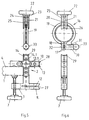
- the outline shape of the independent receiving ring 16 is best recognizable from the individual representations in the 5 and 6.
- the receiving ring has 16th the shape of a one-piece pipe clamp with two radially projecting flanges 17, between which a Gap 18 in the thickness of the webs of the double-T profiles is released.
- the almost closed ring body 19 contains a radial extension of the gap 18 running threaded bore 20 with a therein mounted tension screw 21 with outer handwheel 22.
- a pressure bracket 23 is free on the clamping screw 21 rotatably supported by a locking ring 24 an axial displacement is prevented.
- the legs 25 of the pressure bracket 23 are at their free ends with each a V-cut 26.
- V-cut 27, 28 or 29 is also at the free ends of the legs 9, 10 and Approach 11.
- the V-cuts act when clamping a rod 26 on the one hand and one of the other V-cuts 27, 28 or 29 together (see Fig. 2, 3 or 6).
- a lateral extension 30 On a flange 17 of the receiving ring 16 is a lateral extension 30 with a transverse bore 31 molded.
- a spring-loaded pin 32 mounted on his outer end carries an operating button 33. In the The rest position penetrates the free end of the locking pin 31 in an aligned bore of the opposite Flange.
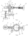
- FIGS. 5 and 6 show the holding device in one Form of use, for example, on a vertical wall is braced and serves one vertical rod to hold. Will she however, in this form of use on a table top attached, it can be used to hold a horizontal Serve rod.
- the use form of FIGS. 5 and 6 is for example applicable when it comes to a Table top one horizontally above it this extending rod with the table top too connect.
Landscapes
- Engineering & Computer Science (AREA)
- General Engineering & Computer Science (AREA)
- Mechanical Engineering (AREA)
- Clamps And Clips (AREA)
- Load-Engaging Elements For Cranes (AREA)
- Walking Sticks, Umbrellas, And Fans (AREA)
- Holders For Apparel And Elements Relating To Apparel (AREA)
Abstract
Description
Die Erfindung bezieht sich auf eine Haltevorrichtung
für Stangen, Rohre oder dergleichen, insbesondere für
Sonnenschirme, gemäß dem Oberbegriff des Anspruchs 1.The invention relates to a holding device
for rods, pipes or the like, especially for
Parasols, according to the preamble of
Eine Haltevorrichtung dieser Art ist seit Jahren bekannt, siehe z.B. DE-U-8 712 448, DE-A-3 619 467; sie wird in Eisenwarenhandlungen oder im Zusammenhang mit Garten- und Freizeitmöbeln in Fachgeschäften angeboten. In der Regel besteht sie aus einem U-förmigen Bügelelement zum Aufsetzen auf eine Tischkante, wobei am unteren Schenkel in einer Gewindebohrung eine Feststellschraube gelagert ist. An dem in der Gebrauchsstellung senkrechten Steg des Bügelelements ist ein Ring angeformt, der in einer Gewindebohrung in der Wandung eine etwa radial stehende, von Hand bedienbare Druckschraube enthält. Zum Halter eines Sonnenschirmes wird die Haltevorrichtung an geeigneter Stelle eines Gartentisches oder dergleichen verspannt. Anschließend wird die Stange des Sonnenschirmes in den Ring von oben so weit eingeschoben, daß sie mit ihrer Spitze in das Erdreich eindringt. Danach wird die Druckschraube angezogen.A holding device of this type has been around for years known, see e.g. DE-U-8 712 448, DE-A-3 619 467; it is used in hardware stores or in Connection with garden and leisure furniture in Specialty shops offered. As a rule, it consists of a U-shaped bracket element to be placed on a Edge of the table, being on the lower leg in one Threaded hole a locking screw is mounted. On the vertical web of the A ring is formed on the bracket element, which in a Threaded hole in the wall approximately radial contains standing, manually operated pressure screw. The becomes the holder of a parasol Holding device at a suitable location Clamped garden table or the like. Subsequently the rod of the parasol is in the ring from above inserted so far that they tip into the Soil penetrates. Then the pressure screw dressed.
Die bekannte einteilige Haltevorrichtung ist außer für eine Verwendung im vorstehend beschriebenen Sinne für andere Arten der Halterung von Stangen oder Rohren nicht geeignet. So ist eine solche Haltevorrichtung beispielsweise dann nicht einsetzbar, wenn zum Halten einer senkrecht verlaufenden Stange keine Tischplatte, dafür aber ein senkrechtes Wandelement zur Verfügung steht. Auch ist eine solche Haltevorrichtung nicht geeignet, um eine waagerecht verlaufende Stange mit einer Tischplatte zu verbinden. Hier will die Erfindung Abhilfe schaffen.The known one-piece holding device is except for a use in the sense described above for other types of support for rods or tubes not suitable. Such is a holding device for example, cannot be used when holding a vertical bar no table top, but a vertical wall element is available stands. Such a holding device is also not suitable for using a horizontal rod to connect a table top. This is where the invention wants Remedy.
Die Aufgabe der Erfindung besteht dementsprechend darin, eine Haltevorrichtung für Stangen, Rohre oder dergleichen zu verbessern und weiter zu entwickeln mit dem Ziel, daß sie für unterschiedliche Anwendungsfälle gleichermaßen gut verwendbar ist.The object of the invention is accordingly therein, a holding device for rods, pipes or to improve and develop the same with the aim that they can be used for different applications is equally usable.
Ausgehend von der bekannten Haltevorrichtung besteht die Lösung dieser Aufgabe erfindungsgemäß darin, daß das Bügelelement im wesentlichen wie der Buchstabe H gestaltet ist und daß die Flansche wahlweise auf einen der freien Schenkel oder auf den Quersteg des Bügelelements aufsteckbar und mittels einer Arretierung am Bügelelement verriegelbar sind.Based on the known holding device the solution of this task according to the invention in that the bracket element essentially how the letter H is designed and that the flanges optionally on one of the free ones Leg or on the crossbar of the bracket element attachable and by means of a lock on Bracket element can be locked.
Vorteilhafte Weiterbildungen sind in den Unteransprüchen beschrieben.Advantageous further developments are in the Subclaims described.
Nach einer ersten zweckmäßigen Weiterbildung ist vorgesehen, daß der in Verlängerung der Gewindebohrung verlaufende freie Schenkel des Bügelelements als Doppel-T-Profil mit zur Bohrungsachse querstehendem Steg ausgebildet ist und daß der gegenüberliegende freie Schenkel und teilweise der Quersteg ebenfalls als Doppel-T-Profile, jedoch mit parallel zur Bohrungsachse verlaufendem Steg ausgebildet sind.After a first useful training provided that the extension of the threaded bore running free legs of the bracket element as Double-T profile with a transverse to the bore axis Web is formed and that the opposite free legs and partly the crossbar also as Double T profiles, but with parallel to the bore axis extending web are formed.
Gemäß einer anderen Weiterbildung haben die Flansche des Aufnahmeringes eine solche Dicke, daß sie auf die Doppel-T-Profile von ihren Stirnseiten her aufschiebbar sind und einzeln in je einem Profilkanal formschlüssig einliegen. Damit ist ein starrer Zusammenhalt zwischen Aufnahmering und Bügelelement gewährleistet.According to another development, the flanges of the receiving ring such a thickness that it on the Double-T profiles can be pushed on from their end faces are form-fitting and individually in each profile channel inlay. So there is a rigid cohesion between Receiving ring and bracket element guaranteed.
Zur Arretierung des Aufnahmeringes in der jeweiligen Stellung sind an den Stegen der Doppel-T-Profile Arretiermittel wie aufeinanderfolgende Bohrungen oder Zacken vorgesehen. Nach einer anderen Weiterbildung ist in Bohrungen der Flansche des Aufnahmeringes ein verschiebbarer, federbelasteter Arretierstift gelagert, der in der Gebrauchsstellung des Aufnahmeringes formschlüssig in eine Bohrung bzw. zwischen zwei Zacken eingreift.To lock the receiving ring in the respective Position on the webs of the double-T profiles Locking means such as successive holes or Peaks provided. According to another training course into holes in the flanges of the mounting ring slidable, spring-loaded locking pin, in the use position of the receiving ring positively in a hole or between two teeth intervenes.
Um den Aufnahmering auch am Quersteg des Bügelelements in verschiedenen Stellungen bzw. Abständen anbringen zu können, ist es zweckmäßig, den Quersteg an der von der Gewindebohrung abgewandten Seite durch einen Ansatz über die Schenkel hinaus zu verlängern, und zwar deckungsgleich als Doppel-T-Profil.Around the receiving ring also on the crossbar of the bracket element attach in different positions or intervals can, it is appropriate to the crossbar on the Thread hole facing away from one side to extend beyond the thighs congruent as a double-T profile.
Zur Erzielung einer verbesserten Zentrierung der Stange oder des Rohres im Aufnahmering ist es zweckmäßig, daß der Schenkel in Verlängerung der Gewindebohrung an seinem Stirnende einen V-Einschnitt mit zur Ebene seines Profilsteges parallelen Kanten aufweist. In gleicher Weise sind der andere Schenkel und der Ansatz am Quersteg gestaltet.To achieve an improved centering of the rod or the tube in the receiving ring, it is appropriate that the leg in the extension of the threaded hole his forehead a V-cut to the plane of its profile web has parallel edges. In the other leg and the neck are the same designed on the crossbar.
Eine andere Weiterbildung betrifft die Mittel zum Verspannen einer Stange oder eines Rohres im Aufnahmering. Zu diesem Zweck ist am Aufnahmering in einer radialen Gewindebohrung, die den Flanschen diametral gegenüberliegt eine Spannschraube vorgesehen, wobei an der Spannschraube an ihrem rückwärtigen Ende, an der diese ein Handrädchen trägt, ein Druckbügel in U-Form frei drehbar gelagert ist, dessen Schenkel zu beiden Seiten des Aufnahmeringes verlaufen und an ihrem freien Ende je einen V-Einschnitt mit parallel zur Ringachse verlaufenden Kanten aufweisen. Zusammen mit dem jeweils gegenüberliegenden V-Einschnitt ist so eine selbsttätige Zentrierung der vom Aufnahmering umschlossenen Stange gewährleistet, selbst dann, wenn die Stange erheblich dünner ist als der Innendurchmesser des Halteringes.Another training relates to the means for Clamping a rod or a tube in the Receiving ring. For this purpose is on the receiving ring in a radial threaded hole that the flanges a tension screw is provided diametrically opposite, being at the tension screw at its rear end, on which this carries a handwheel, a pressure bracket in U-shape is freely rotatable, the legs of which run on both sides of the receiving ring and on hers free end each with a V-cut parallel to Have edges running along the ring axis. Along with the opposite V-cut is one automatic centering of the receiving ring enclosed rod ensures even if the bar is considerably thinner than that Inner diameter of the retaining ring.
Nach einer anderen vorteilhaften Weiterbildung ist an einem Flansch des Aufnahmeringes ein seitlicher Ansatz angeformt, an dem in einer Querbohrung der federbelastete Arretierstift gelagert ist. Zum Erfassen des Arretierstiftes dient ein an seinem Ende befestigter Kugelkopf.According to another advantageous training is on a flange of the receiving ring a side approach integrally formed on the in a transverse bore spring-loaded locking pin is mounted. To capture the locking pin serves one at its end attached ball head.
Der Hauptvorteil der neuen Haltevorrichtung ist darin zu sehen, daß sie für zahlreiche, unterschiedliche Anwendungsfälle, sei es im Haushalt oder im Garten- oder Freizeitbereich, zum Halten von Stangen oder Rohren geeignet ist. Das Bügelelement kann je nach Bedarf an einer waagerechten Tischplatte oder an der Kante einer senkrechten Wand befestigt werden. Je nachdem, ob die Stange oder das Rohr in der Gebrauchsstellung senkrecht oder waagerecht verlaufen soll, wird der Aufnahmering an einem Schenkel oder am Quersteg des Bügelelements angesetzt. Dabei ist er für das Aufnehmen von Stangen mit unterschiedlichen Stärken leicht bedarfsgerecht einstellbar. Dadurch, daß die parallelen Flansche des Aufnahmeringes jeweils formschlüssig in einem Profilkanal einliegen, ist ein starrer Zusammenhalt zwischen Bügelelement und Aufnahmering gewährleistet. Das Umsetzen des Aufnahmeringes kann mit wenigen Handgriffen vorgenommen werden.The main advantage of the new holding device is in it to see that they are for numerous, different Use cases, be it in the household or in Garden or leisure area, for holding poles or pipes is suitable. The bracket element can vary Need for a horizontal table top or on the Edge of a vertical wall. Each after whether the rod or the pipe in the Use position vertically or horizontally should, the receiving ring on one leg or on Cross bar of the bracket element attached. He is for picking up bars with different strengths easily adjustable according to need. Because the parallel flanges of the receiving ring each is a positive fit in a profile channel rigid cohesion between bracket element and Receiving ring guaranteed. Implementing the Recording ring can be done in a few simple steps will.
Ein Ausführungsbeispiel der Erfindung ist in der Zeichnung schematisch dargestellt und wird nachfolgend näher erläutert. Es zeigt:
- Fig. 1
- eine Seitenansicht einer Haltevorrichtung gemäß der Erfindung in einer ersten Benutzungsform,
- Fig. 2
- eine Draufsicht der Haltevorrichtung nach Fig. 1,
- Fig. 3
- eine Seitenansicht der Haltevorrichtung in einer zweiten Benutzungsform,
- Fig. 4
- eine Draufsicht der Haltevorrichtung nach Fig. 3,
- Fig. 5
- eine Seitenansicht der Einzelteile der Haltevorrichtung vor dem Zusammensetzen für eine dritte Benutzungsform und
- Fig. 6
- eine Stirnansicht der Einzelteile der Haltevorrichtung nach Fig. 5.
- Fig. 1
- 2 shows a side view of a holding device according to the invention in a first form of use,
- Fig. 2
- 2 shows a top view of the holding device according to FIG. 1,
- Fig. 3
- a side view of the holding device in a second use,
- Fig. 4
- 3 shows a top view of the holding device according to FIG. 3,
- Fig. 5
- a side view of the individual parts of the holding device before assembly for a third form of use and
- Fig. 6
- 5 shows an end view of the individual parts of the holding device according to FIG. 5.
Die Fig. 1 und 2 zeigen die Haltevorrichtung bei der
Benutzung zum Halten eines Sonnenschirmes an einem
Gartentisch oder dergleichen. Von dem Gartentisch ist
lediglich das Ende der Tischplatte 1 angedeutet. Das im
wesentlichen H-förmig gestaltete Bügelelement 2 ist mit
zwei parallelen Schenkeln 3, 4 von der Seite her auf
die Tischplatte 1 aufgeschoben. Im Schenkel 3 ist in
einer Gewindebohrung 5 eine Feststellschraube 6 mit
einem äußeren Handrädchen 7 gelagert. Durch Anziehen
der Feststellschraube 6 ist das Bügelelement 2 mit der
Tischplatte 1 fest verspannbar.1 and 2 show the holding device in the
Use to hold an umbrella on one
Garden table or the like. From the garden table is
only the end of the
Die Länge des Steges 8 des Bügelelements ist so
bemessen, daß die Haltevorrichtung an Tischplatten mit
unterschiedlichen Stärken verwendbar ist.The length of the
Außer den beiden vorgenannten Schenkeln 3, 4 enthält
das Bügelelement 2 etwa gleich lange freie Schenkel 9,
10 und einen Ansatz 11 als Verlängerung des Steges 8.
Die Schenkel 9, 10 sowie der Steg 8 teilweise und der
Ansatz 11 sind als Doppel-T-Profil ausgebildet. Die
Herstellung des Bügelelements kann im metallischen
Druckgußverfahren erfolgen.In addition to the two
Am Schenkel 9 hat das Doppel-T-Profil eine solche Lage,
daß sein Steg 12 quer zur Achse der Gewindebohrung 5
und damit quer zur Ebene des Bügelelements 2 verläuft.
Anders verhält es sich mit den Doppel-T-Profilen im
anderen Schenkel 10, im Quersteg 8 und im Ansatz 11,
bei denen der Steg 13 bzw. 14 in der Mittenebene des
Bügelelements und damit senkrecht zum Steg 12 verläuft. On the
In allen Stegen 12, 13, 14 sind eine Anzahl von
Bohrungen 12.1, 13.1. und 14.1 mit etwa gleichem
Abstand hintereinander angeordnet.In all
In dem Schenkel 4 ist an der Innenfläche eine
keilförmige Einkerbung 15 mittig zur Achse der
Gewindebohrung 5 angebracht, die im Falle einer
Befestigung der Haltevorrichtung an einem Rundstab
einen rutschfesten Halt gewährleisten soll.In the
Die Umrißform des selbständigen Aufnahmeringes 16 ist
am besten erkennbar aus den Einzeldarstellungen in den
Fig. 5 und 6. Im wesentlichen hat der Aufnahmering 16
die Gestalt einer einteiligen Rohrschelle mit zwei
radial abstehenden Flanschen 17, zwischen denen ein
Spalt 18 in der Stärke der Stege der Doppel-T-Profile
frei gelassen ist. Der nahezu geschlossene Ringkörper
19 enthält in Verlängerung des Spaltes 18 eine radial
verlaufende Gewindebohrung 20 mit einer darin
gelagerten Spannschraube 21 mit äußerem Handrädchen 22.
Auf der Spannschraube 21 ist ein Druckbügel 23 frei
drehbar gelagert, der durch einen Sicherungsring 24 an
einer Axialverschiebung gehindert ist. Die Schenkel 25
des Druckbügels 23 sind an ihrem freien Ende mit je
einem V-Einschnitt 26 versehen.The outline shape of the
Auch an den freien Enden der Schenkel 9, 10 und des
Ansatzes 11 befindet sich je ein V-Einschnitt 27, 28
bzw. 29. Je nach der Anwendung des Aufnahmeringes
wirken beim Einspannen einer Stange die V-Einschnitte
26 einerseits und einer der übrigen V-Einschnitte 27,
28 bzw. 29 zusammen (vgl. Fig. 2, 3 oder 6).Also at the free ends of the
An einem Flansch 17 des Aufnahmeringes 16 ist ein
seitlicher Ansatz 30 mit einer Querbohrung 31
angeformt. In der Querbohrung 31 ist ein
federbelasteter Stift 32 gelagert, der an seinem
äußeren Ende einen Betätigungsknopf 33 trägt. In der
Ruhestellung dringt das freie Ende des Arretierstiftes
31 in eine fluchtende Bohrung des gegenüberliegenden
Flansches ein.On a
Zum Verbinden des Aufnahmeringes 16 mit dem
Bügelelement 2 werden die Flansche 17 bei
zurückgezogenem Arretierstift 32 auf das freie Ende
eines Doppel-T-Profils aufgeschoben, bis der
Arretierstift in eine Bohrung einrasten kann. Je nach
der Stärke der zu haltenden Stange wird der
Aufnahmering 16 dabei mehr oder weniger weit auf das
jeweilige Doppel-T-Profil aufgeschoben. Die Fig. 1, 2
sowie 3, 4 zeigen jeweils den Aufnahmering 16 in einer
Stellung, in der die größtmögliche Weite des
Aufnahmeringes für das Einsetzen einer Stange zur
Verfügung steht.To connect the receiving
Die Fig. 3 und 4 zeigen die Haltevorrichtung in einer Benutzungsform, bei der sie beispielsweise an einer senkrechten Wand verspannt ist und dazu dient, eine senkrecht verlaufende Stange zu halten. Wird sie dagegen in dieser Benutzungsform an einer Tischplatte angebracht, kann sie zum Halten einer waagerechten Stange dienen. Die Benutzungsform der Fig. 5 und 6 ist beispielsweise anwendbar, wenn es darum geht, an einer Tischplatte eine oberhalb derselben waagerecht zu dieser verlaufende Stange mit der Tischplatte zu verbinden.3 and 4 show the holding device in one Form of use, for example, on a vertical wall is braced and serves one vertical rod to hold. Will she however, in this form of use on a table top attached, it can be used to hold a horizontal Serve rod. The use form of FIGS. 5 and 6 is for example applicable when it comes to a Table top one horizontally above it this extending rod with the table top too connect.
Claims (10)
- A holding device for bars, tubes or the like, in particular for a sun umbrella, which has a yoke element (2) for fitting on to a table edge and a fixing screw (6), wherein two parallel limbs (3, 4) in the position of use receive a plate or the like between them and can be braced by means of the fixing screw (6) which is mounted in a screwthreaded bore (5) in a limb (3), the holding device further includes a receiving ring (16) for receiving a bar which can be braced in the receiving ring (16), and the yoke element (2) and the receiving ring (16) are independent individual parts, wherein the receiving ring (16) is formed substantially like a pipe clamp with two substantially radially projecting flanges (17) which define a gap (18), characterised in that the yoke element (2) is shaped substantially like the letter 'H' and that the flanges (17) can be fitted selectively on to one of the free limbs (9 or 10) or on to the cross bar portion (8) of the yoke element (2) and can be locked to the yoke element (2) by means of an arresting arrangement.
- A holding device according to claim 1 characterised in that the free limb (9) of the yoke element (2), which extends in line with the screwthreaded bore (5), is in the form of a double-T-profile member with a web portion (12) which is disposed transversely with respect to the axis of the bore and that the oppositely disposed free limb (10) and in part the cross bar portion (8) are also in the form of double-T-profile members, but with the web portion (13 and 14 respectively) extending parallel to the axis of the bore.
- A holding device according to claim 2 characterised in that the flanges (17) of the receiving ring (16) are of such a thickness that they can be pushed on to the double-T-profile members from the ends thereof and individually lie in positively locking engagement in a respective passage in the profile member.
- A holding device according to claim 2 or claim 3 characterised in that provided on the web portions (12, 13 or 14 respectively) of the double-T-profile members are arresting means such as successive bores (12.1, 13.1 or 14.1 respectively) or teeth.
- A holding device according to claim 4 characterised in that mounted in bores (31) in the flanges (17) of the receiving ring (16) is a displaceable, spring-loaded arresting pin (32) which in the position of use of the receiving ring (16) engages in positively locking engagement into a bore (12.1, 13.1 or 14.1) or between two teeth.
- A holding device according to one of claims 2 to 5 characterised in that the cross bar portion (8) of the yoke element (2) is prolonged beyond the lateral limbs (4, 10) at the side remote from the screwthreaded bore (5) by a projection (11).
- A holding device according to one of claims 1 to 6 characterised in that at its end, in line with the screwthreaded bore (5), the limb (9) has a V-shaped groove (27) with edges parallel to the plane of its web portion (12).
- A holding device according to claim 6 or claim 7 characterised in that the projection (11) and the free limb (10) disposed at that side have at their end a respective V-shaped groove (29 and 28 respectively) with edges extending parallel to the plane of the associated web portion (14 and 13 respectively).
- A holding device according to one of claims 1 to 8 characterised in that a clamping screw (21) is mounted on the receiving ring (16) in a radial screwthreaded bore (20) which is in diametrally opposite relationship to the flanges (17) and that a pressure stirrup (23) of U-shape is freely rotatably mounted on the clamping screw (21) at its rearward end at which it carries a small hand wheel, the limbs (25) of the stirrup extending on both sides of the receiving ring (16) and at their free ends each having a respective V-shaped groove (26) with edges extending parallel to the axis of the ring.
- A holding device according to one of claims 5 to 9 characterised in that formed on a flange (17) of the receiving ring (18) is a lateral projection (30) on which the arresting pin (32) is mounted in a transverse bore (31).
Applications Claiming Priority (2)
| Application Number | Priority Date | Filing Date | Title |
|---|---|---|---|
| DE9311951U DE9311951U1 (en) | 1993-08-11 | 1993-08-11 | Holding device for rods, pipes or the like. |
| DE9311951U | 1993-08-11 |
Publications (2)
| Publication Number | Publication Date |
|---|---|
| EP0638257A1 EP0638257A1 (en) | 1995-02-15 |
| EP0638257B1 true EP0638257B1 (en) | 1998-10-14 |
Family
ID=6896620
Family Applications (1)
| Application Number | Title | Priority Date | Filing Date |
|---|---|---|---|
| EP94111033A Expired - Lifetime EP0638257B1 (en) | 1993-08-11 | 1994-07-15 | Holding device for rods, tubes and the like |
Country Status (4)
| Country | Link |
|---|---|
| EP (1) | EP0638257B1 (en) |
| AT (1) | ATE172081T1 (en) |
| DE (3) | DE9311951U1 (en) |
| ES (1) | ES2126679T3 (en) |
Families Citing this family (6)
| Publication number | Priority date | Publication date | Assignee | Title |
|---|---|---|---|---|
| US5582384A (en) * | 1995-01-13 | 1996-12-10 | Schoen; Hans | Holding device for rods, tubes, etc. |
| FR2771612B1 (en) * | 1997-11-28 | 2000-06-16 | Biyong Boniface | DEVICE FOR FIXING AN UMBRELLA OR THE LIKE ON A MOBILE ELEMENT SUCH AS A WHEELCHAIR, BICYCLE, STROLLER, LANDAU, OR ON A FIXED ELEMENT SUCH AS A BALCONY, TABLE, LONG CHAIR AND ALLOWING ITS ORIENTATION |
| CN102434768A (en) * | 2011-10-24 | 2012-05-02 | 蚌埠日月仪器研究所有限公司 | Device for rapidly installing oil-field measurement and control boxes |
| EP2733409A1 (en) * | 2012-11-16 | 2014-05-21 | Keysheen Industry (Shanghai) Co., Ltd. | Fixing device |
| GB201709682D0 (en) * | 2017-06-16 | 2017-08-02 | Breton Daniel | An improved basketball pole holder |
| CN112161160B (en) * | 2020-09-28 | 2022-03-15 | 四川富美建利科技有限公司 | Video monitoring fixing device based on deep water net cage |
Family Cites Families (15)
| Publication number | Priority date | Publication date | Assignee | Title |
|---|---|---|---|---|
| DE667812C (en) * | 1938-11-21 | Emil Mueller | On a grid, e.g. B. a balcony grid, flagpole holder to be attached | |
| DE356450C (en) * | 1922-07-25 | Edmund Lehmann | Pocket tripod | |
| CH181668A (en) * | 1935-02-26 | 1935-12-31 | Glatz Spahn Albert | Umbrella holder. |
| FR1026188A (en) * | 1950-09-15 | 1953-04-24 | Foolproof clamping device, especially for pipe fittings or the like | |
| US3321161A (en) * | 1966-06-29 | 1967-05-23 | Metelco Inc | Hanger clamp |
| US3572623A (en) * | 1969-08-06 | 1971-03-30 | Chester A Lapp | Pipe hanger clamp |
| DE7709904U1 (en) * | 1977-03-29 | 1977-07-28 | Siemens Ag, 1000 Berlin Und 8000 Muenchen | FASTENING ELEMENT FOR CABLE AND HOLLOW CONDUCTOR CLAMPS |
| DE8215214U1 (en) * | 1982-05-26 | 1982-09-02 | Fa. Willi Flott, 4773 Möhnesee | Bracket for attaching a lamp or the like. |
| US4607829A (en) * | 1984-09-24 | 1986-08-26 | Suska Charles R | Clamping apparatus |
| DE3619467A1 (en) * | 1986-06-10 | 1987-12-17 | Alfer Alu Fertigbau | Clamping device (work-holding fixture) |
| US4941633A (en) * | 1986-11-21 | 1990-07-17 | Walker Robert L | Rope support device |
| DE8712448U1 (en) * | 1987-09-15 | 1987-11-05 | Fischer, Anneliese, 8700 Würzburg | Holding device for work tools |
| IT1236604B (en) * | 1989-12-29 | 1993-03-18 | Antonio Muraca | STICK HOLDER SUPPORT, PARTICULARLY TO BE APPLIED ADVENTELY TO THE BODYWORK OF THE VEHICLES TO HOLD THE HANDLE OF AN UMBRELLA OR SIMILAR IN ORDER TO PROTECT AGAINST ATMOSPHERIC AGENTS PEOPLE OPERATING AROUND THE VEHICLE, PARTICULARLY IN THE AROUND OF THE VEHICLE |
| US5172885A (en) * | 1991-03-25 | 1992-12-22 | Kreischer Marjory K | Umbrella support |
| DE9105424U1 (en) * | 1991-05-02 | 1992-09-10 | Reiling, Karl, 7535 Königsbach-Stein | Universal holder |
-
1993
- 1993-08-11 DE DE9311951U patent/DE9311951U1/en not_active Expired - Lifetime
- 1993-11-16 DE DE4339070A patent/DE4339070A1/en not_active Withdrawn
-
1994
- 1994-07-15 EP EP94111033A patent/EP0638257B1/en not_active Expired - Lifetime
- 1994-07-15 ES ES94111033T patent/ES2126679T3/en not_active Expired - Lifetime
- 1994-07-15 DE DE59407078T patent/DE59407078D1/en not_active Expired - Fee Related
- 1994-07-15 AT AT94111033T patent/ATE172081T1/en not_active IP Right Cessation
Also Published As
| Publication number | Publication date |
|---|---|
| DE9311951U1 (en) | 1993-10-14 |
| ATE172081T1 (en) | 1998-10-15 |
| DE59407078D1 (en) | 1998-11-19 |
| DE4339070A1 (en) | 1995-02-16 |
| EP0638257A1 (en) | 1995-02-15 |
| ES2126679T3 (en) | 1999-04-01 |
Similar Documents
| Publication | Publication Date | Title |
|---|---|---|
| DE2742112C2 (en) | Bracket for a hand shower | |
| DE69922501T2 (en) | DEVICE FOR SPINE-STEM OSTEOSYNTHESIS WITH CLAMP AND LOCKING | |
| DE69815119T2 (en) | STOPPING DEVICE | |
| EP0297033A2 (en) | Fixing element for a rod | |
| DE2905848C2 (en) | ||
| EP0638257B1 (en) | Holding device for rods, tubes and the like | |
| AT393303B (en) | DEVICE FOR CONNECTING COMPONENTS | |
| DE9212843U1 (en) | Holder for attaching a U-lock to a bicycle | |
| EP1568299B1 (en) | Device for hanging the bows of a bow curtain on a curtain rod | |
| DE4326477C2 (en) | Device for releasably connecting a guide rod | |
| DE3611445C2 (en) | ||
| DE19501567C2 (en) | table | |
| DE3401426A1 (en) | Attachment device for the mutual attachment of two node, curved or tubular elements of an installation system which are provided with plastic sheaths | |
| DE3725111C2 (en) | ||
| DE1952505A1 (en) | tripod | |
| DE3411022C2 (en) | Card holder | |
| DE2943625C2 (en) | Pipe clamp | |
| DE3513842C2 (en) | Table, especially camping or garden table | |
| DE8628957U1 (en) | Christmas tree stand | |
| CH711506B1 (en) | Folding mechanism for a table. | |
| DE29613155U1 (en) | Device for releasably connecting structural parts | |
| DE8027713U1 (en) | SLIDING HAND SHOWER BRACKET ON A SLIDE ROD | |
| DE7037959U (en) | Pipe clamp | |
| AT352331B (en) | DEVICE FOR CONNECTING TWO PIPES, ARRANGED AT AN ANGLE, TO ONE LEG OR OTHER PIPE | |
| DE10162863A1 (en) | Mounting for attaching foot to item of furniture comprises clip with U-shaped cross-section which is attached to foot and slides over curved plate screwed on to item |
Legal Events
| Date | Code | Title | Description |
|---|---|---|---|
| PUAI | Public reference made under article 153(3) epc to a published international application that has entered the european phase |
Free format text: ORIGINAL CODE: 0009012 |
|
| AK | Designated contracting states |
Kind code of ref document: A1 Designated state(s): AT CH DE ES FR IT LI |
|
| 17P | Request for examination filed |
Effective date: 19950704 |
|
| GRAG | Despatch of communication of intention to grant |
Free format text: ORIGINAL CODE: EPIDOS AGRA |
|
| 17Q | First examination report despatched |
Effective date: 19980421 |
|
| GRAG | Despatch of communication of intention to grant |
Free format text: ORIGINAL CODE: EPIDOS AGRA |
|
| GRAH | Despatch of communication of intention to grant a patent |
Free format text: ORIGINAL CODE: EPIDOS IGRA |
|
| GRAH | Despatch of communication of intention to grant a patent |
Free format text: ORIGINAL CODE: EPIDOS IGRA |
|
| GRAA | (expected) grant |
Free format text: ORIGINAL CODE: 0009210 |
|
| AK | Designated contracting states |
Kind code of ref document: B1 Designated state(s): AT CH DE ES FR IT LI |
|
| REF | Corresponds to: |
Ref document number: 172081 Country of ref document: AT Date of ref document: 19981015 Kind code of ref document: T |
|
| REG | Reference to a national code |
Ref country code: CH Ref legal event code: EP |
|
| REF | Corresponds to: |
Ref document number: 59407078 Country of ref document: DE Date of ref document: 19981119 |
|
| ITF | It: translation for a ep patent filed | ||
| ET | Fr: translation filed | ||
| REG | Reference to a national code |
Ref country code: CH Ref legal event code: NV Representative=s name: LUCHS & PARTNER PATENTANWAELTE |
|
| REG | Reference to a national code |
Ref country code: ES Ref legal event code: FG2A Ref document number: 2126679 Country of ref document: ES Kind code of ref document: T3 |
|
| PLBE | No opposition filed within time limit |
Free format text: ORIGINAL CODE: 0009261 |
|
| STAA | Information on the status of an ep patent application or granted ep patent |
Free format text: STATUS: NO OPPOSITION FILED WITHIN TIME LIMIT |
|
| 26N | No opposition filed | ||
| PGFP | Annual fee paid to national office [announced via postgrant information from national office to epo] |
Ref country code: AT Payment date: 20020731 Year of fee payment: 9 |
|
| PGFP | Annual fee paid to national office [announced via postgrant information from national office to epo] |
Ref country code: CH Payment date: 20020806 Year of fee payment: 9 |
|
| PGFP | Annual fee paid to national office [announced via postgrant information from national office to epo] |
Ref country code: ES Payment date: 20020814 Year of fee payment: 9 |
|
| PGFP | Annual fee paid to national office [announced via postgrant information from national office to epo] |
Ref country code: DE Payment date: 20020926 Year of fee payment: 9 Ref country code: FR Payment date: 20020926 Year of fee payment: 9 |
|
| PG25 | Lapsed in a contracting state [announced via postgrant information from national office to epo] |
Ref country code: AT Free format text: LAPSE BECAUSE OF NON-PAYMENT OF DUE FEES Effective date: 20030715 |
|
| PG25 | Lapsed in a contracting state [announced via postgrant information from national office to epo] |
Ref country code: ES Free format text: LAPSE BECAUSE OF NON-PAYMENT OF DUE FEES Effective date: 20030716 |
|
| PG25 | Lapsed in a contracting state [announced via postgrant information from national office to epo] |
Ref country code: LI Free format text: LAPSE BECAUSE OF NON-PAYMENT OF DUE FEES Effective date: 20030731 Ref country code: CH Free format text: LAPSE BECAUSE OF NON-PAYMENT OF DUE FEES Effective date: 20030731 |
|
| PG25 | Lapsed in a contracting state [announced via postgrant information from national office to epo] |
Ref country code: DE Free format text: LAPSE BECAUSE OF NON-PAYMENT OF DUE FEES Effective date: 20040203 |
|
| REG | Reference to a national code |
Ref country code: CH Ref legal event code: PL |
|
| PG25 | Lapsed in a contracting state [announced via postgrant information from national office to epo] |
Ref country code: FR Free format text: LAPSE BECAUSE OF NON-PAYMENT OF DUE FEES Effective date: 20040331 |
|
| REG | Reference to a national code |
Ref country code: FR Ref legal event code: ST |
|
| REG | Reference to a national code |
Ref country code: ES Ref legal event code: FD2A Effective date: 20030716 |
|
| PG25 | Lapsed in a contracting state [announced via postgrant information from national office to epo] |
Ref country code: IT Free format text: LAPSE BECAUSE OF NON-PAYMENT OF DUE FEES;WARNING: LAPSES OF ITALIAN PATENTS WITH EFFECTIVE DATE BEFORE 2007 MAY HAVE OCCURRED AT ANY TIME BEFORE 2007. THE CORRECT EFFECTIVE DATE MAY BE DIFFERENT FROM THE ONE RECORDED. Effective date: 20050715 |