EP0637371B1 - A device for measuring an angle in a piece - Google Patents
A device for measuring an angle in a piece Download PDFInfo
- Publication number
- EP0637371B1 EP0637371B1 EP94907078A EP94907078A EP0637371B1 EP 0637371 B1 EP0637371 B1 EP 0637371B1 EP 94907078 A EP94907078 A EP 94907078A EP 94907078 A EP94907078 A EP 94907078A EP 0637371 B1 EP0637371 B1 EP 0637371B1
- Authority
- EP
- European Patent Office
- Prior art keywords
- feelers
- base
- piece
- feeler
- angle
- Prior art date
- Legal status (The legal status is an assumption and is not a legal conclusion. Google has not performed a legal analysis and makes no representation as to the accuracy of the status listed.)
- Expired - Lifetime
Links
Images


Classifications
-
- B—PERFORMING OPERATIONS; TRANSPORTING
- B21—MECHANICAL METAL-WORKING WITHOUT ESSENTIALLY REMOVING MATERIAL; PUNCHING METAL
- B21D—WORKING OR PROCESSING OF SHEET METAL OR METAL TUBES, RODS OR PROFILES WITHOUT ESSENTIALLY REMOVING MATERIAL; PUNCHING METAL
- B21D5/00—Bending sheet metal along straight lines, e.g. to form simple curves
- B21D5/02—Bending sheet metal along straight lines, e.g. to form simple curves on press brakes without making use of clamping means
- B21D5/0209—Tools therefor
-
- G—PHYSICS
- G01—MEASURING; TESTING
- G01B—MEASURING LENGTH, THICKNESS OR SIMILAR LINEAR DIMENSIONS; MEASURING ANGLES; MEASURING AREAS; MEASURING IRREGULARITIES OF SURFACES OR CONTOURS
- G01B5/00—Measuring arrangements characterised by the use of mechanical techniques
- G01B5/24—Measuring arrangements characterised by the use of mechanical techniques for measuring angles or tapers; for testing the alignment of axes
-
- G—PHYSICS
- G01—MEASURING; TESTING
- G01B—MEASURING LENGTH, THICKNESS OR SIMILAR LINEAR DIMENSIONS; MEASURING ANGLES; MEASURING AREAS; MEASURING IRREGULARITIES OF SURFACES OR CONTOURS
- G01B7/00—Measuring arrangements characterised by the use of electric or magnetic techniques
- G01B7/30—Measuring arrangements characterised by the use of electric or magnetic techniques for measuring angles or tapers; for testing the alignment of axes
-
- Y—GENERAL TAGGING OF NEW TECHNOLOGICAL DEVELOPMENTS; GENERAL TAGGING OF CROSS-SECTIONAL TECHNOLOGIES SPANNING OVER SEVERAL SECTIONS OF THE IPC; TECHNICAL SUBJECTS COVERED BY FORMER USPC CROSS-REFERENCE ART COLLECTIONS [XRACs] AND DIGESTS
- Y10—TECHNICAL SUBJECTS COVERED BY FORMER USPC
- Y10S—TECHNICAL SUBJECTS COVERED BY FORMER USPC CROSS-REFERENCE ART COLLECTIONS [XRACs] AND DIGESTS
- Y10S72/00—Metal deforming
- Y10S72/702—Overbending to compensate for springback
Definitions
- the present invention relates to a device for measuring an angle in a piece, particularly an angle formed in a piece of sheet metal by bending, during the operation to bend the piece in a bending press having a punch and a V-shaped die which cooperate with each other.
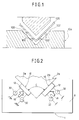
- One of these known devices provides for the use of two or more distance-measuring sensors 100 disposed on each face 102 of the V-shaped groove in the die 104.
- This known device calculates the angle formed in the piece by bending, by means of direct distance measurements between the surface of the piece and the respective wall 102 of the V-shaped groove in the die 104, made with pointed feelers 100 at two points spaced a known distance apart in a direction perpendicular to the bending line.
- the object of the present invention is to provide a device for measuring an angle in a piece, which is not affected by the aforementioned disadvantages and which provides very precise and reproducible measurements regardless of the condition of the surface of the piece.
- this object is achieved by the provision of a device having the characteristics forming the subject of Claim 1.
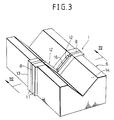
- a device is for measuring an angle formed in a piece of sheet metal 2 by bending, during a bending operation carried out on the piece by means of a bending press comprising a punch 4 and a die 6.
- the device 1 comprises a base 8 constituted by a steel plate a few millimeters thick with holes 10 for enabling it to be fixed between two bodies 11 so as to form a compact block which is inserted in a slot 13 in the die 6.
- the device 1 has two feelers 12 disposed approximately symmetrically with respect to an axis A which passes through the vertex of the V-shaped groove 14 in the die 6.
- Each feeler 12 has an active surface 16 which extends beyond the respective wall of the groove 14. The active surfaces 16 of the feelers 12 are thus intended to contact respective portions 2a. 2b of the piece being bent.
- each feeler 12 is connected to the base 8 by means of two connecting elements 18 formed integrally with the base 8 and with the feeler 12.
- the connecting elements 18 are constituted by thin, multiple-S-shaped strips of material.
- the particular system for connecting the feelers 12 to the base 8 means that the feelers 12 are completely free of each other kinematically.
- the connecting elements 18 also constitute resilient thrust means which allow each feeler 12 to perform a translatory and a pivoting movement relative to the base 8, within a plane perpendicular to the bending line, completely independently of the movement of the other feeler.
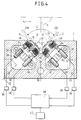
- Each feeler 12 is H-shaped with two portions 20, 22 joined together by a central web 24.
- the connecting and thrust elements 18 are very flexible in a direction perpendicular to the active surfaces 16 of the respective feelers 12.
- the feelers 12 and the connecting and thrust elements 18 are formed integrally from a steel plate constituting the base 8. More precisely, each feeler 12 and its connecting and thrust elements 18 are produced by the removal of material from the region 26 which is shaded in Figure 4a.
- the base 8 is made of a hardened steel with a high yield point, of the type used for the manufacture of springs.
- each support 30 carries a pair of distance-measuring sensors 32 formed according to the prior art, which are housed - parallel to each other - and lying in a plane perpendicular to the vertex of the V-shaped groove 14, in a chamber 33 defined between the two bodies 11.
- Each sensor 32 faces a respective corresponding element 34 fixed to the feeler 12.
- the sensors 32 are high-sensitivity contactless electromagnetic probes which generate magnetic fields, the intensities of which depend upon the distances between the corresponding elements 34 and the end surfaces of the sensors 32.
- the surfaces of the corresponding elements 34 which face the sensors 32 are approximately parallel to the active surfaces 16 of the feelers 12.
- Each sensor 32 is connected to an amplifier 36 which sends a signal indicative of the distance measured to a control unit 38.
- the control unit 38 operates a numerically-controlled actuator 40 which brings about the relative movement of the bending tools 4, 6.
- a sample punch with a vertex angle V ⁇ which is known with an accuracy equal to or better than that with which the subsequent measurements are to be made is mounted on the press instead of the bending punch.
- V ⁇ vertex angle
- the active surfaces 16 of the feelers 12 which are acted on by the connecting and thrust elements 18 adapt precisely to the surfaces of the sample element.
- the distance measurements supplied by the four sensors 32 are stored by the control unit 38 and adopted as reference values for the subsequent measurements.
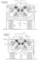
- a flat piece of sheet metal 2 is placed on the die 6 in a position perpendicular to the bending plane defined by the direction of the relative movement of the punch 4 and the die 6 ( Figure 6).
- the punch 4 which is operated by the actuator 40, controlled by the control unit 38, then enters the groove 14 in the die 6 forming a bend in the piece 2 ( Figure 7).
- the feelers 12 are retracted relative to the walls of the groove 14 against the resilient action of the connecting and thrust elements 18.
- the relative bending travel of the tools 4, 6 corresponds to a bending angle C slightly smaller than the desired value.
- the tools 4, 6 are moved apart far enough to leave the sheet metal free so that the two portions 2a, 2b of the piece being worked can return resiliently (Figure 8).
- the sheet metal 2 is in a generic position relative to the groove 14 and the vertex of the sheet-metal dihedron remains sufficiently parallel to the vertex of the V-shaped groove 14.
- the active surfaces 16 of the feelers 12 are kept in contact with the respective portions 2a, 2b of the piece 2 by the resilient force exerted by the connecting and thrust elements 18.
- the feelers 12 can adapt precisely to the position adopted by the piece 2, since each feeler is free to move within the plane, independently of the other.
- the feelers 12 thus adopt angular orientations the same as those of the portions 2a, 2b of the piece 2. These angular orientations are also independent of the distances of the feelers 12 from the vertex of the bent sheet-metal dihedron. These distances may even be different for the two feelers 12.
- the contact between the feelers 12 and the piece 2 takes place over a large surface 16 and therefore the determination of the bending angle is not affected by the surface roughness of the piece.
- the distance-measuring sensors 32 associated with each feeler 12 are spaced a known distance apart so that the control unit 38 can determine the actual angle C formed in the bent piece by comparing the distance measurements provided by the four sensors 32 with those obtained during the calibration.
- the control unit 38 checks the bend angle, measured against the desired bend angle, and operates the actuator 40 again so as to make the distance D between the vertices of the tools 4, 6 slightly less than the distance set during the preliminary bending.
- the method described is repeated until the distance D determined corresponds to the desired bend angle C.
- This value is then stored and is used for all the subsequent bending operations on pieces having the same physical characteristics.
- the device 1 enables the bend angle of the piece to be measured continuously and corrections to be made, should the need arise.
- FIG. 9 to 13 show a variant of the device according to the invention. Elements corresponding to those described above are indicated by the same reference numerals.
- the device 1 is slidable in the slot 13 in the die 6 in the directions indicated by the double arrow E.
- a pair of compression springs 44 urges the device 1 towards a raised rest position shown in Figures 9 and 10.
- the force of these springs is much greater than that generated by the connecting and thrust elements 18 of the feelers 12.
- the two bodies 1 between which the base 8 is clamped form a V-shaped groove 46, the sides of which are substantially larger than the sides of the V-shaped groove 14 in the die 6 and which - in the rest position - project relative to the corresponding walls of the V-shaped groove 14 in the die 6, which is indicated in chain line in Figure 10.
- the bodies 11 have a pair of edges 48 at the upper ends of the V-shaped groove 46; these edges 48 constitute reference surfaces for abutting the portions 2a, 2b of the bent piece in order to define a predetermined relative position between the device 1 and the piece of sheet metal 2 during the measurement of the bend angle.
- the angle of the bend formed in the sheet metal 2 is generally larger than the angle of the V-shaped grooves 46 in the bodies 11.
- the relative positions of the movable measuring device 1 and the sheet metal 2 is therefore determined by the edges 48.
- the lengths of the surfaces 16 of the feelers 12 may be substantially greater, since the V-shaped grooves 46 in the bodies 11 may be larger than the V-shaped groove 14 in the die.
- the V-shaped groove 46 must, however, be smaller than the smaller of the two portions 2a and 2b of the sheet metal against which it bears. Since the size of the V-shaped groove 46 in the measuring device 1 is not restricted by the size of the V-shaped groove 14 in the die 6, clearly the measuring device can be used for a plurality of tools with V-shaped grooves 14 of different sizes.
- the modes of operation of the device described above provide for the bending movement of the bending press to be brought about by a numerically-controlled actuator 40.
- the same device can, of course, be used on a manually-operated bending press.
- the control unit 38 is limited to presenting the data relating to the angle measured, for example, on a display.
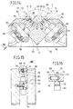
- Figure 14, 15 and 16 show an another variant of the device according to the invention. Elements corresponding to those described above are indicated by the same reference numerals.
- This device includes a base 60.
- the base 60 is formed approximately in a shape of rectangular block and has a V-shaped groove 62 defined by two groove surface 68 on the top portion of the base 60; the V-shaped groove 62 receives the folded piece 2.
- the base 60 has a gap 64 which opens mainly toward the bottom surface thereof.
- the base 60 further has a pair of portion 66 at a suitable position of the top portion thereof.
- Each portion 66 is provided with a hole 70 that communicate from the gap 64 to the groove 62.
- a pair of feelers 72 are provided in the holes 70 respectively.
- the each feeler 72 is movably disposed within a plane perpendicular to the vertex of the V-shaped groove 62.
- the each feeler 72 is formed in a shape of a rectangular plate and has a active surface 73 so as to be in contact with the piece 2.
- the each feeler has a longitudinal slot 74.
- a pin 76 is inserted in the longitudinal slot 74, and the both ends of the pin 76 are fixed to the inside wall of the hole 70.
- the feeler 72 has a bottom portion 78. In this configuration, the feeler 72 is movable in the direction perpendicular to the groove surface 68 and rotatable about the pin 76.
- a pair of distance measuring sensors 84 for each feeler 72 are fixed to the base 60 by the bracket 86.
- a rod 80 is inserted in each distance-measuring sensor 84.
- the each rod 80 is pushed against right and left end of the bottom portion 78 of the feeler 72 by a spring 82.
- the each rod 80 is extended in the direction which is perpendicular to the groove surface 68 and is within the plane perpendicular to the vertex of the V-shaped groove 62.
- the distance-measuring sensors 84 can measure the position of the rod 80 with respect to the distance-measuring sensors 84. In this configuration, when the piece 2 folded by the punch 4 and die 6 comes into contact with the each feeler 72, the pair of rods 80 are retracted into the sensors 84 respectively. Each position of the rod is then measured by the sensor 84 and the bend angle C is calculated by the control unit.
- the pair of feelers 72 are movable and rotatable independently within the plane perpendicular to the vertex of the V-shaped groove 62, and therefore the active surface 73 of the feelers 72 can adapt precisely to the surface of the pieces 2. Accordingly this device can measure the bend angle C precisely. Further, this device has the feelers 72 each of which has large active surface 73. Therefore the determination of the bending angle C is not affected by surface roughness of the piece 2. Moreover the feelers 72 are provided on the base 60 rather than on the die.
- the bend angle C can be precisely measured by means of the active surfaces 73, even if the V-shaped groove 14 of the die 6 is very small; this is because the lateral width of the active surface 73 could be longer than the width of the V-shaped groove 14 of the die 6. Consequently this device can measure the bent angle C precisely.
- FIG. 17A, 17B and 17C Another enbodymennt of this invention shown in Figures 17A, 17B and 17C provides for the use of two feelers 110 having large contact surfaces which are urged resiliently against respective portions of the bent-metal dihedron 112.
- the feelers 110 are articulated about the same shaft 114 which is carried by a base 116 movable perpendicular to the bending line. Means 118 are associated with the two feelers for measuring the angle formed between them.
- the feelers are associated with respective springs 120 which impart to the feelers 110 forces which make them pivot about their common articulation axis 114 in order to close them against the facing surfaces of the sheet-metal dihedron 112.
- the base 116 on which the feelers 110 are articulated is associated with an actuator 122 which urges the base 116 towards the vertex of the piece in a direction perpendicular to the bending line.
Abstract
Description
Claims (20)
- A device for measuring an angle in a piece (2), comprising:characterised in thata base (8,60);feelers (12,72) which are movable relative to the base (8,60) and each of which has contacting means (16,73) for contacting a respective portion (2a,2b) of the piece (2) during the measurement, the feelers (12,72) are completely free of each other kinematically;thrust means (18,82) for bringing the contacting means (16,73) of the feelers (12,72) into contact with the respective portions (2a,2b) of the piece (2) being measured, the thrust means (18,82) associated with one feeler (12,72) are completely independent of the thrust means (18,82) associated with another feeler (12,72) and allows the respective feeler (12,72) to perform a translatory movement relative to the base (8,60) completely independently of the movement of the other feeler (12,72) and sensor means (32,84) for detecting the positions of the feelers (12,72) relative to the base (8,60)each feeler (12,72) comprises an active surface for contacting the respective portion (2a,2b) of the piece (2) and the sensor means (32,84) comprises a pair of distance- measuring elements spaced at a known distance apart and lying in a plane of the angle to be measured, the measuring elements being associated with two different points with the movable feeler (12,72) wherein a pair of said feelers (12,72) and the associated measuring elements are located within the base (8,60).
- The device according to Claim 1, wherein the feelers (12, 72) are free to perform translatory and pivoting movements independently of each other, within a plane perpendicular to a vertex of the angle to be measured.
- The device according to Claim 2, wherein each of the feelers (12) is connected to the base (8) solely by means of resilient members (18) constituting the thrust means.
- The device according to Claim 1, wherein the feelers (12) are formed integrally with the base (8) and the thrust means are constituted by integral connecting means (18) disposed between the feelers (12) and the base (8) and manufactured so as to be very flexible in a direction perpendicular to the active surfaces (16) of the respective feelers (12).
- The device according to Claim 4, wherein the each feeler (12) has an H-shaped configuration with a central web (24) which joins together two parallel portions (20, 22) between which two thin strips (18) constituting integral connecting elements between the feeler (12) and the base (8) extend.
- The device according to Claim 5, wherein the strips extend in a multiple-S-shaped configuration.
- The device according to Claim 4, wherein the feelers (12) and the integral connecting elements (18) are formed by the removal of material from a region (26) complementary to a solid area defining the feelers (12) and the integral connecting elements (18).
- The device according to Claim 1, wherein the sensor means comprise, for the each movable feeler (12), a pair of substantially parallel distance-measuring elements (32).
- The device according to Claim 1, wherein the base (8) is movable relative to the piece (2) and is urged towards the piece (2) by actuator means (44), the base having abutment means (48) for defining a stable position for the execution of the measurement, in which the base (8) is kept in a fixed position relative to the piece (2) by the action of the actuator means.
- The device according to Claim 9, wherein the actuator means comprise at least one resilient element (44) which can keep the base (8) urged against the piece (2) with a force substantially greater than the force with which the thrust means (18) keep the feelers (12) in contact with the respective portions (2a, 2b) of the piece (2).
- The device according to Claim 1, further comprising a calibration member having two reference surfaces for cooperating with the feelers (12), the reference surfaces being inclined to each other at a reference angle which is known with an accuracy equal to or better than that with which the measurement is to be made.
- The device according to Claim 1, for measuring the angle (C) formed in a piece of sheet metal (2) by bending, during an operation to bend the piece (2) in a bending press having a punch (4) which cooperates with a die (6) having a V-shaped groove (14), wherein the base (8) is mounted in a slot (13) in the die (6) so that a plane of symmetry of the V-shaped groove (14) in the die (6) coincides substantially with a plane of symmetry of a V-shaped groove (46) in a body (11) of the measuring device (1).
- The device according to Claim 9 for measuring the angle (C) formed in a piece of sheet metal (2) by bending, during an operation to bend the piece (2) in a bending press having a punch (4) which cooperates with a die (6) having a V-shaped groove (14), wherein the base (8) is mounted in a slot (13) in the die (6) so that a plane of symmetry of the V-shaped groove (14) in the die (6) coincides substantially with a plane of symmetry of a V-shaped groove (46) in a body (11) of the measuring device (1), and a sides of the V-shaped groove (46) in the body (11) are substantially larger than a sides of the V-shaped groove (14) in the die (6).
- The device according to Claim 12 or Claim 13, further comprising sensor means (32) for generating electrical signals indicative of the angle measured and for sending signals to a control unit (38), the control unit (38) being adapted to control an actuator (40) which brings about the relative movement of the punch (4) and the die (6).
- The device according to Claim 14, wherein the control unit (38) is arranged to effect the bending in successive steps, in which a relative distance between the punch (4) and the die (6) decreases progressively in each bending step in comparison with the preceding step, starting from an initial value which corresponds to a bend angle greater than the desired value, the various bending steps alternating with measurements of the the angle (C).
- The device according to Claim 1, further comprising a device for displaying a value of the angle measured.
- The device according to claim 2, further comprising rods (80) which are contacted with the feeler (72), wherein the thrust means are resilient means (82) which push the rods (80) towards the feeler (72), and the sensor means are distance-measuring sensors (84) which can measure a position of the rods (80) with respect to the distance-measuring sensors (84).
- The device according to claim 17, wherein the base (60) has holes (70) in which the feelers (72) are inserted movably and rotatably.
- The device according to claim 18, wherein the each feeler (72) has a longitudinal slot (74), the base is provided with pins (76) in the holes (70), and the each pin (76)is inserted in the longitudinal slot (74).
- The device according to claim 17, wherein the distance-measuring means (84) are formed in cylinder shape and receive the rods (80) therein mobably.
Applications Claiming Priority (3)
| Application Number | Priority Date | Filing Date | Title |
|---|---|---|---|
| ITTO930117A IT1260892B (en) | 1993-02-23 | 1993-02-23 | DEVICE TO MEASURE THE CORNER OF A PIECE, IN PARTICULAR THE CORNER OF BENDING A PIECE OF SHEET METAL. |
| ITTO930117 | 1993-02-23 | ||
| PCT/JP1994/000257 WO1994019662A1 (en) | 1993-02-23 | 1994-02-21 | A device for measuring an angle in a piece |
Publications (2)
| Publication Number | Publication Date |
|---|---|
| EP0637371A1 EP0637371A1 (en) | 1995-02-08 |
| EP0637371B1 true EP0637371B1 (en) | 1998-07-22 |
Family
ID=11411164
Family Applications (1)
| Application Number | Title | Priority Date | Filing Date |
|---|---|---|---|
| EP94907078A Expired - Lifetime EP0637371B1 (en) | 1993-02-23 | 1994-02-21 | A device for measuring an angle in a piece |
Country Status (8)
| Country | Link |
|---|---|
| US (1) | US5584199A (en) |
| EP (1) | EP0637371B1 (en) |
| JP (1) | JP3110761B2 (en) |
| KR (1) | KR100321220B1 (en) |
| AT (1) | ATE168770T1 (en) |
| DE (1) | DE69411821T2 (en) |
| IT (1) | IT1260892B (en) |
| WO (1) | WO1994019662A1 (en) |
Cited By (1)
| Publication number | Priority date | Publication date | Assignee | Title |
|---|---|---|---|---|
| WO2013188896A1 (en) | 2012-06-18 | 2013-12-27 | Trumpf Maschinen Austria Gmbh & Co. Kg. | Bending press having an angle-measuring device and method for determining the bending angle |
Families Citing this family (20)
| Publication number | Priority date | Publication date | Assignee | Title |
|---|---|---|---|---|
| PT1011886E (en) * | 1997-06-20 | 2002-07-31 | Luciano Gasparini | PRESS FOR FOLDING METAL SHEETS |
| IT1311827B1 (en) * | 1999-04-16 | 2002-03-19 | Luciano Gasparini | SELF-CENTERING TILTING FORK OF THE FORK, PARTICULARLY FOR MEASURING ON FOUR POINTS OF THE |
| EP1083403A1 (en) * | 1999-09-08 | 2001-03-14 | Bystronic Laser AG | Procedure and device to determine the bending angle of objects |
| KR100519521B1 (en) * | 1999-10-07 | 2005-10-05 | 무라타 기카이 가부시키가이샤 | A press machine and its driving method |
| CN1262366C (en) * | 2000-08-11 | 2006-07-05 | 株式会社阿玛达 | Bending method and device therefor |
| JP4637396B2 (en) * | 2001-04-12 | 2011-02-23 | 株式会社アミテック | Angle measuring instrument |
| US20030121303A1 (en) * | 2001-12-28 | 2003-07-03 | Lanni Arthur L. | Die set with position sensor mounted thereon |
| JP2006205256A (en) | 2004-12-27 | 2006-08-10 | Amada Co Ltd | Work bending angle detecting device and work bending machine |
| DE102006050687B4 (en) * | 2006-10-24 | 2010-01-28 | Hans Schröder Maschinenbau GmbH | Method for measuring and / or correcting the shape of the workpiece after forming by bending |
| JP5125275B2 (en) | 2007-02-05 | 2013-01-23 | トヨタ自動車株式会社 | Fuel cell and vehicle equipped with fuel cell |
| AR080194A1 (en) | 2010-02-17 | 2012-03-21 | Dsm Ip Assets Bv | LIQUID ANTIMICROBIAL COMPOSITIONS |
| CN102120230B (en) * | 2010-12-03 | 2012-12-05 | 中联重科股份有限公司 | Device and method for measuring bending angle of bent piece |
| JP5883627B2 (en) * | 2011-12-02 | 2016-03-15 | 株式会社アマダホールディングス | Bending angle detector for plate bending machine |
| AT513279B1 (en) * | 2012-11-08 | 2014-03-15 | Trumpf Maschinen Austria Gmbh | Measuring device and measuring method for measuring the thickness of a plate-shaped object and bending machine |
| AT515279B1 (en) * | 2014-06-12 | 2015-08-15 | Trumpf Maschinen Austria Gmbh | Calibration tool for an angle measuring tool in a bending punch and method for calibrating the angle measuring tool |
| DE102014225169A1 (en) * | 2014-12-08 | 2016-06-09 | Robert Bosch Gmbh | Pneumatic measuring mandrel and measuring system |
| JP6537915B2 (en) * | 2015-07-27 | 2019-07-03 | Ntn株式会社 | Pitch cone angle measuring method and measuring apparatus |
| AT521529B1 (en) * | 2018-07-27 | 2020-04-15 | Trumpf Maschinen Austria Gmbh & Co Kg | Bending device and method for determining at least one material parameter or processing parameter for a workpiece processing device |
| KR102062619B1 (en) * | 2019-07-22 | 2020-01-06 | 금강메탈 주식회사 | Forging mold manufacturing device for automobile parts porduction |
| KR102167710B1 (en) * | 2019-10-23 | 2020-10-19 | 장춘기 | Forging mold manufacturing device for automobile parts porduction |
Family Cites Families (13)
| Publication number | Priority date | Publication date | Assignee | Title |
|---|---|---|---|---|
| FR1425315A (en) * | 1964-10-14 | 1966-01-24 | Promecan Sisson Lehmann | Improvements to bending tools |
| DE2044199C3 (en) * | 1970-09-07 | 1974-12-05 | Karl Mengele & Soehne Maschinenfabrik Und Eisengiesserei Guenzburg-Donau, 8870 Guenzburg | Angle measuring and control device on bending machines, in particular free bending machines |
| FR2362722A1 (en) * | 1976-08-27 | 1978-03-24 | Promecan Sisson Lehmann | Sheet folding machine bend angle indicator - has two parallel spring loaded sensing rods in contact with sheet during bending |
| IT1072273B (en) * | 1977-02-01 | 1985-04-10 | Selecontrol Sas | DEVICE FOR THE DETECTION AND ADJUSTMENT OF BENDING ANGLES PARTICULARLY SUITABLE FOR PRESSES-FOLDERS |
| DE3008701A1 (en) * | 1980-03-07 | 1981-09-24 | Johann 7057 Leutenbach Hess | ANGLE MEASURING DEVICE FOR BENDING PRESSES |
| JPS5982119A (en) * | 1982-11-01 | 1984-05-12 | Komatsu Ltd | Bending angle detector for bending machine |
| US4864509A (en) * | 1987-09-29 | 1989-09-05 | The Boeing Company | Method and related apparatus for controlling the operation of a press brake |
| DE3739173A1 (en) * | 1987-11-19 | 1989-06-01 | Feintool Int Holding | METHOD AND DEVICE FOR BENDING WORKPIECES |
| US5062283A (en) * | 1988-07-19 | 1991-11-05 | Yamazaki Mazak Kabushiki Kaisha | Press brake and a workpiece measuring method in the press brake |
| US5148693A (en) * | 1989-11-14 | 1992-09-22 | Amada Company, Limited | Method and a device for detecting folding angles of a metal sheet during the folding and a method for folding of a metal sheet |
| SE505985C2 (en) * | 1989-11-14 | 1997-10-27 | Amada Co Ltd | Method and apparatus for sensing bending angles of a metal sheet during bending |
| CH689613A5 (en) * | 1992-10-20 | 1999-07-15 | Beyeler Machines Sa | Device for measuring the bending angle of a sheet in a press. |
| JP2630720B2 (en) * | 1992-11-06 | 1997-07-16 | 丸機械工業株式会社 | Bending angle detecting device for plate material and method of operating press machine using the same |
-
1993
- 1993-02-23 IT ITTO930117A patent/IT1260892B/en active IP Right Grant
-
1994
- 1994-02-21 KR KR1019940703825A patent/KR100321220B1/en not_active IP Right Cessation
- 1994-02-21 US US08/325,330 patent/US5584199A/en not_active Expired - Lifetime
- 1994-02-21 WO PCT/JP1994/000257 patent/WO1994019662A1/en active IP Right Grant
- 1994-02-21 DE DE69411821T patent/DE69411821T2/en not_active Expired - Fee Related
- 1994-02-21 AT AT94907078T patent/ATE168770T1/en not_active IP Right Cessation
- 1994-02-21 JP JP06518822A patent/JP3110761B2/en not_active Expired - Fee Related
- 1994-02-21 EP EP94907078A patent/EP0637371B1/en not_active Expired - Lifetime
Cited By (2)
| Publication number | Priority date | Publication date | Assignee | Title |
|---|---|---|---|---|
| WO2013188896A1 (en) | 2012-06-18 | 2013-12-27 | Trumpf Maschinen Austria Gmbh & Co. Kg. | Bending press having an angle-measuring device and method for determining the bending angle |
| US9664493B2 (en) | 2012-06-18 | 2017-05-30 | Trumpf Maschinen Austria Gmbh & Co. Kg. | Bending press having an angle-measuring device and method for determining the bending angle |
Also Published As
| Publication number | Publication date |
|---|---|
| ITTO930117A1 (en) | 1994-08-23 |
| ATE168770T1 (en) | 1998-08-15 |
| KR100321220B1 (en) | 2002-07-02 |
| DE69411821T2 (en) | 1998-12-03 |
| KR950701424A (en) | 1995-03-23 |
| JP3110761B2 (en) | 2000-11-20 |
| JPH07506194A (en) | 1995-07-06 |
| DE69411821D1 (en) | 1998-08-27 |
| WO1994019662A1 (en) | 1994-09-01 |
| EP0637371A1 (en) | 1995-02-08 |
| IT1260892B (en) | 1996-04-29 |
| US5584199A (en) | 1996-12-17 |
| ITTO930117A0 (en) | 1993-02-23 |
Similar Documents
| Publication | Publication Date | Title |
|---|---|---|
| EP0637371B1 (en) | A device for measuring an angle in a piece | |
| US4802357A (en) | Apparatus and method of compensating for springback in a workpiece | |
| CA1174043A (en) | Device for measuring the fold angle in a sheet metal bending press | |
| US4936126A (en) | Press brake with a displacement sensor of electric signal output | |
| US7040129B2 (en) | Sheet working method, sheet working system, and various devices related to such system | |
| US4131008A (en) | Device for measuring the bending angles in plate-bending machines | |
| CZ9904634A3 (en) | Bending press | |
| JPH0318499A (en) | Method and apparatus for manufacturing pressed article with stable dimension | |
| US5806201A (en) | Multi-coordinate touch probe | |
| US5224274A (en) | Contact gage | |
| EP0715552B1 (en) | Adaptive folding | |
| US4813152A (en) | Clearance gauge for setting a tool above a workpiece | |
| EP1123170B1 (en) | Apparatus for bending workpieces and measuring device for such an apparatus | |
| JP2002079319A (en) | Die apparatus in bending machine, bending machine, method for detecting bending angle and bending method | |
| KR102120322B1 (en) | Contact probe structure for tilting driven length measurement | |
| JPH0526481Y2 (en) | ||
| US5904058A (en) | Decamberer | |
| JPS61229421A (en) | Bending method for plate like body | |
| JPH0416166Y2 (en) | ||
| JP2564253Y2 (en) | Back gauge device with home position correction function | |
| JPH0777646B2 (en) | Cross angle zero adjustment method for cross roll type rolling mill | |
| NL1012072C2 (en) | Bending method for plate shaped workpiece, involves stopping return movement of bent workpiece before force with which workpiece is clamped between die and punch falls below predetermined value | |
| JPS6244322Y2 (en) | ||
| JPH03142338A (en) | Deformation extent measuring instrument | |
| NL1015210C1 (en) | Bending method for plate shaped workpiece, involves stopping return movement of bent workpiece before force with which workpiece is clamped between die and punch falls below predetermined value |
Legal Events
| Date | Code | Title | Description |
|---|---|---|---|
| PUAI | Public reference made under article 153(3) epc to a published international application that has entered the european phase |
Free format text: ORIGINAL CODE: 0009012 |
|
| 17P | Request for examination filed |
Effective date: 19941021 |
|
| AK | Designated contracting states |
Kind code of ref document: A1 Designated state(s): AT CH DE FR GB LI SE |
|
| 17Q | First examination report despatched |
Effective date: 19961014 |
|
| GRAG | Despatch of communication of intention to grant |
Free format text: ORIGINAL CODE: EPIDOS AGRA |
|
| GRAG | Despatch of communication of intention to grant |
Free format text: ORIGINAL CODE: EPIDOS AGRA |
|
| GRAG | Despatch of communication of intention to grant |
Free format text: ORIGINAL CODE: EPIDOS AGRA |
|
| GRAH | Despatch of communication of intention to grant a patent |
Free format text: ORIGINAL CODE: EPIDOS IGRA |
|
| GRAH | Despatch of communication of intention to grant a patent |
Free format text: ORIGINAL CODE: EPIDOS IGRA |
|
| GRAA | (expected) grant |
Free format text: ORIGINAL CODE: 0009210 |
|
| AK | Designated contracting states |
Kind code of ref document: B1 Designated state(s): AT CH DE FR GB LI SE |
|
| REF | Corresponds to: |
Ref document number: 168770 Country of ref document: AT Date of ref document: 19980815 Kind code of ref document: T |
|
| REG | Reference to a national code |
Ref country code: CH Ref legal event code: NV Representative=s name: ISLER & PEDRAZZINI AG Ref country code: CH Ref legal event code: EP |
|
| REF | Corresponds to: |
Ref document number: 69411821 Country of ref document: DE Date of ref document: 19980827 |
|
| ET | Fr: translation filed | ||
| PLBE | No opposition filed within time limit |
Free format text: ORIGINAL CODE: 0009261 |
|
| STAA | Information on the status of an ep patent application or granted ep patent |
Free format text: STATUS: NO OPPOSITION FILED WITHIN TIME LIMIT |
|
| 26N | No opposition filed | ||
| REG | Reference to a national code |
Ref country code: GB Ref legal event code: IF02 |
|
| PGFP | Annual fee paid to national office [announced via postgrant information from national office to epo] |
Ref country code: AT Payment date: 20030221 Year of fee payment: 10 |
|
| PGFP | Annual fee paid to national office [announced via postgrant information from national office to epo] |
Ref country code: SE Payment date: 20030224 Year of fee payment: 10 |
|
| PG25 | Lapsed in a contracting state [announced via postgrant information from national office to epo] |
Ref country code: AT Free format text: LAPSE BECAUSE OF NON-PAYMENT OF DUE FEES Effective date: 20040221 |
|
| PG25 | Lapsed in a contracting state [announced via postgrant information from national office to epo] |
Ref country code: SE Free format text: LAPSE BECAUSE OF NON-PAYMENT OF DUE FEES Effective date: 20040222 |
|
| EUG | Se: european patent has lapsed | ||
| PGFP | Annual fee paid to national office [announced via postgrant information from national office to epo] |
Ref country code: CH Payment date: 20060220 Year of fee payment: 13 |
|
| PG25 | Lapsed in a contracting state [announced via postgrant information from national office to epo] |
Ref country code: LI Free format text: LAPSE BECAUSE OF NON-PAYMENT OF DUE FEES Effective date: 20070228 Ref country code: CH Free format text: LAPSE BECAUSE OF NON-PAYMENT OF DUE FEES Effective date: 20070228 |
|
| REG | Reference to a national code |
Ref country code: CH Ref legal event code: PCAR Free format text: ISLER & PEDRAZZINI AG;POSTFACH 1772;8027 ZUERICH (CH) |
|
| REG | Reference to a national code |
Ref country code: CH Ref legal event code: PL |
|
| PGFP | Annual fee paid to national office [announced via postgrant information from national office to epo] |
Ref country code: GB Payment date: 20090223 Year of fee payment: 16 |
|
| PGFP | Annual fee paid to national office [announced via postgrant information from national office to epo] |
Ref country code: DE Payment date: 20090327 Year of fee payment: 16 |
|
| PGFP | Annual fee paid to national office [announced via postgrant information from national office to epo] |
Ref country code: FR Payment date: 20090219 Year of fee payment: 16 |
|
| GBPC | Gb: european patent ceased through non-payment of renewal fee |
Effective date: 20100221 |
|
| REG | Reference to a national code |
Ref country code: FR Ref legal event code: ST Effective date: 20101029 |
|
| PG25 | Lapsed in a contracting state [announced via postgrant information from national office to epo] |
Ref country code: FR Free format text: LAPSE BECAUSE OF NON-PAYMENT OF DUE FEES Effective date: 20100301 |
|
| PG25 | Lapsed in a contracting state [announced via postgrant information from national office to epo] |
Ref country code: DE Free format text: LAPSE BECAUSE OF NON-PAYMENT OF DUE FEES Effective date: 20100901 |
|
| PG25 | Lapsed in a contracting state [announced via postgrant information from national office to epo] |
Ref country code: GB Free format text: LAPSE BECAUSE OF NON-PAYMENT OF DUE FEES Effective date: 20100221 |