EP0637178A1 - Telephone distribution frame - Google Patents
Telephone distribution frame Download PDFInfo
- Publication number
- EP0637178A1 EP0637178A1 EP94401701A EP94401701A EP0637178A1 EP 0637178 A1 EP0637178 A1 EP 0637178A1 EP 94401701 A EP94401701 A EP 94401701A EP 94401701 A EP94401701 A EP 94401701A EP 0637178 A1 EP0637178 A1 EP 0637178A1
- Authority
- EP
- European Patent Office
- Prior art keywords
- profiles
- fixing
- section
- distributor according
- end piece
- Prior art date
- Legal status (The legal status is an assumption and is not a legal conclusion. Google has not performed a legal analysis and makes no representation as to the accuracy of the status listed.)
- Withdrawn
Links
Images


Classifications
-
- H—ELECTRICITY
- H04—ELECTRIC COMMUNICATION TECHNIQUE
- H04Q—SELECTING
- H04Q1/00—Details of selecting apparatus or arrangements
- H04Q1/02—Constructional details
- H04Q1/14—Distribution frames
-
- H—ELECTRICITY
- H04—ELECTRIC COMMUNICATION TECHNIQUE
- H04Q—SELECTING
- H04Q1/00—Details of selecting apparatus or arrangements
- H04Q1/02—Constructional details
- H04Q1/06—Cable ducts or mountings specially adapted for exchange installations
Definitions
- the present invention relates to a telephone distributor, comprising a series of carrier profiles on which are mounted connection equipment, said connection blocks, and accessory equipment, such as jumpers guide rings, in particular.
- connection blocks are connected to the so-called input and output cable lines to be connected, these cables or their lines being guided and held against the profiles up to the level substantially of each connection block concerned. They are presented in rows, on the front face of a single-sided distributor, and receive the garters on the front face, these garters allowing a patching of the connections. They leave between their rows or both rows a free space in which the guide rings of the jumpers define a guide path, laterally on the rows and behind the connection blocks. These guide rings are ajar opposite the front face of the distributor and make the garters accessible from the front face.
- These guide rings are of axis parallel to the profiles, for guiding jumpers along the rows of connection blocks, and may in addition be for some of them of axis transverse to the profiles for the additional guide of garters transversely. rows of terminal blocks.
- the document FR-A-2446040 describes such a telephone distributor.
- the guide rings are fixed on the first vertical profiles, using L-shaped fixing lugs.
- the connection blocks are fixed on horizontal U-shaped spacers, themselves fixed on the first profiles. and protruding at the front of the rings, or are fixed on second vertical profiles located at the front of the first and being assembled to them by horizontal U-shaped spacers.
- the guide rings are properly oriented on the fixing lugs for their horizontal and vertical orientation on the first vertical profiles.
- the fixing lugs are in turn of two different lengths, depending on the orientation of the rings, to separate from one another the plane of the vertical paths and the plane of the horizontal path or paths defined by the horizontal rings and the rings vertical.
- the distributor may conventionally include other accessory equipment, such as in particular cable support shelves on one and / or the other of the terminal parts of the profiles, steps on the terminal part of the profiles.
- accessory equipment such as in particular cable support shelves on one and / or the other of the terminal parts of the profiles, steps on the terminal part of the profiles.
- the document EP-A-0074898 also describes a distributor of this type, in which the profiles carry all the equipment for the direct organization of the distributor by column. These profiles have pairs of fins on their faces, for mounting and maintaining the equipment mounting brackets or the direct support of certain accessory equipment, such as steps, cable support shelves, which lend themselves to it.
- the equipment mounting brackets are specific to each type of equipment and are generally U-shaped dishes or angled legs and different lengths. They are themselves fixed to the fins of the front face of the profiles or between the fins of their lateral faces, using a screw or a set of screws passing through one of their legs and anchored in the fins between them.
- the present invention aims to rationalize the production of distributors, by minimizing the types of mounting brackets for various equipment, and making assembly operations easy and quick.
- a telephone distributor comprising load-bearing profiles, aligned one after the other, connection equipment, called connection blocks, connected to input and output cable lines and to jumpers, and accessory equipment, consisting for at least part of them by guide rings of the garters, and in which said profiles have longitudinal fins for mounting the equipment, said connection blocks form rows parallel to the profiles at least on one front face of the distributor and leave at least one lateral access along each row, and said guide rings maintained on said profiles by individual fixing elements are opposite the lateral accesses defined along said rows, characterized in that said elements of fixing are identical modules and each have a flat base, having two faces main, an end piece, protruding on a first of the main faces of the base, an axial bore, passing through the base and the end piece and receiving a clamping screw in an associated terminal nut, locked in rotation, and a pair of lugs protruding on the second main face of the base, for mounting the fixing module between the fins of the profiles, and in that said guide rings each comprise a lateral
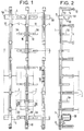
- the distributor shown in Figures 1 and 2 is single sided. Alternatively, it can also be double-sided.
- This distributor includes a series of carrier profiles 1, identical and aligned, on which are mounted connection equipment 2, called connection blocks, and accessory equipment essentially consisting of guide rings 3A and 3B, only shown and assigned to guide of garters. It is described by considering the vertical profiles 1, as is the general case, but these profiles 1 can just as easily be horizontal.
- connection blocks 2 are fixed at the end of horizontal brackets 4, themselves fixed to the sections 1 and belonging with these sections to the support structure. They are connected to the input lines of one or more input cables, for some of them, and to the output lines of one or more output cables for the others, these cables or their lines not shown being guided along the profiles from one and / or the other of their ends where the cables are retained.
- the garters are guided by the guide rings 3A parallel to the sections 1, these rings 3A being horizontal, and by the guide rings 3B transversely to the sections 1, these rings 3B being vertical. They are connected to connection blocks 2 on the front of the distributor or connection blocks on the supporting structure, for line connections input lines to the output lines and possible mixing of these connections.
- the guide rings 3A are along the sections 1.
- the guide rings 3B are at one or at defined horizontal levels, in particular at the lower level of the distributor.
- the carrier sections 1 are held relative to each other by horizontal spacers 5 for assembly.
- These spacers are dishes which also ensure in this embodiment the fixing of the distributor.
- they have their terminal portions 5A, bent at a right angle and projecting from the front of the distributor, in which holes 5B are provided, for their fixing by screws to the side walls or sides of the distributor.
- They can also or alternatively be fixed in a similar manner to a rear wall or to a wall.
- the distributor can alternatively be fixed to the ground and relative to the ceiling of a room.
- Profiles 1 are of the standard type used in particular in the field of robotics for the construction of chassis for special assembly machines.
- Potenses 4 are sections of profile chosen identical to profiles 1.
- each pair of fins, the internal cheek opposite and the two side spacers corresponding define between them a housing 9 along each side of the profile.
- Each housing 9 has a middle opening 9A defined between the two outer fins of each face of the profile.
- brackets 4 are identical to the profiles, their parts being simply designated by the references of those of the profiles.
- fixing elements 10 all identical and called fixing modules, ensure the fixing of the brackets 4 and of the guide rings 3A and 3B on the sections 1 and that of the connection blocks 2 at the end of the brackets.
- connection blocks 2 mounted on the profiles form parallel rows on the front of the distributor. They leave an access interval between the rows, or alternatively every two rows.
- the guide rings 3A and 3B mounted on the profiles are at the rear of the connection blocks and opposite these access intervals. They define the jumper paths between them, the jumpers being connected to the connection blocks on their front face.
- the guide rings 3A are horizontal and define a lateral guide path along each row. They are preferably grouped together on certain sections 1, by defining two vertical paths on either side of each section concerned.
- the guide rings 3B are vertical and preferably define a horizontal lower guide path or similarly a horizontal upper guide path. Each horizontal guide path is at the rear of the connection blocks. It is made offset relative to the vertical paths directly by the mounting mode of the rings 3A and 3B concerned on each of the fixing modules.
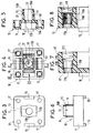
- the fixing modules 10 are described with reference to FIGS. 3 to 7.
- Each of them has a relatively flat base 11, the main opposite faces of which are substantially square and are substantially equal in side to the side of the external section of the profiles, and a nozzle 12, projecting from one of the two main faces of the base and centered on this main face.
- Each has an axial bore 13 passing through the base and the end piece.
- the end piece 12 is of substantially square cross section, which is truncated by slots 14 along its edges. These slots 14 divide the nozzle into four fins denoted 15 and made slightly elastic. The inner faces 15A of the fins 15 are chamfered along the slots, as well as the end edge 15B of the outer faces of the fins.
- This fixing module has two opposite centering tabs 16, projecting from the other main face of the base, called the centering face. These tabs are centered on two of the opposite sides of the centering face. They are straight and each of length substantially equal to the width of the longitudinal opening 9A between the external fins 7 of the sections 1 and of the brackets 4.
- This module further comprises four through holes 17, provided near the four corners of the base, and four cavities or cavities 18, provided between the holes 17, on the main face carrying the end piece.
- the axial bore 13 is of square section along the end piece, of circular section in the junction part of the end piece on the base, this circular section being part of the square section along the end piece. It then opens into a rectangular opening 13A, of upper section, on the side of the centering face of the base. Two facing impressions 13B, semi-circular and centered on the two large edges of this opening 13A define between them, in this opening, the possible housing for a screw head.
- the fixing modules 10 are relatively rigid, except for the end piece made elastic by its four longitudinal slots. They are preferably made of plastic and produced by molding.
- the holes 17 in the base are specified with reference to Figures 8 and 9. Each is divided into three parts 17A, 17B and 17C in succession.
- the end portion 17A on the centering face of the base and the intermediate portion 17B are of circular section.
- the end portion 17C on the main face carrying the endpiece is of square section.
- the diameter of the terminal part 17A is slightly less than that of the intermediate part, itself slightly smaller than the side of the part 17C.
- a metal insert 19, tubular and internally threaded, is mounted in each hole 17, to reinforce the resistance of a fixing produced by screws blocked in these holes 17 as well equipped.
- This insert introduced by part 17C has its front end abutting against the annular shoulder 17D defined between parts 17A and 17B. It has for its own blocking in the hole, a rear shoulder 19A, abutting against the annular shoulder 17E defined between the parts 17B and 17C, and an annular tooth periphery 19B anchored in the edge of the intermediate part 17B.
- Figure 9 shows one of the brackets 4 fixed to one of the profiles 1 and equipped to be able to fix a connection block at the end.
- These two fixings are provided by two fixing modules 10, to each of which are associated a blocking counter piece 20, a clamping screw 21 with head 21A and a nut 22 or 23.
- the counter locking piece 20 is partially received in the end piece 12 of the fixing module. It has a conical shape on the outside. Its cross section is square with substantially rounded corners as can be seen in FIG. 10. Its small base 20A is on the side smaller than that of the cross section of the bore 13 of the end piece and its large base 20B with a side larger and at least equal to that of the cross section of the end piece. It has an axial hole 20C of circular cross section, which corresponds to that of the circular part of the bore 13 at the junction of the base and the end piece.
- the nut 22 is rhomboidal. It is relatively flat and has two substantially parallel front faces. Its dimensions are such that it engages in one of the housings 9 of the profile 1 directly through the opening 9A and locks in this housing by rotation of a quarter of a hole.
- the nut 23 has a non-truncated square section, which corresponds substantially to the internal section of the brackets, in which it is threaded and stops in rotation.
- the bracket 4 is fixed to the profile 1 by first inserting the blocking counter piece 20 in the end piece 12 then the screw 21 in the hole 20C and the part of the bore 13 extending the hole 20C in the base 11, up to the stop of the head 21A against the large base 20B of the counter locking piece 20.
- the rhomboidal nut 22 is then screwed loosely onto the end of the screw.
- the fixing module 10 thus equipped is threaded into one of the two ends of the bracket 4, with the head 21A of the screw 21 and the end piece being housed in the internal section of the bracket, until the stop of the base against the end of the stem.
- the nut 22 is itself engaged in the housing 9 of the front face of the profile, while maintaining the base 12 of the fixing module against the end of the bracket and by engaging the centering lugs 16 in the opening 9A of the housing. Then tighten, using a screwdriver, from the other end of the bracket 4, the screw on the nut 22, which gives rise first of all to the quarter-turn rotation of the nut for its blocking in rotation, then in advance of the blocking counterpiece in the end piece and in the deformation of the elastic fins 15 of the end piece until the blockage resulting from the end piece 12 and therefore from the fixing module 10 in the bracket and on the profile.
- the mounting of the fixing module 10 on the other free end of the bracket is done in a comparable manner, but this time by threading the square nut 23, mounted on the screw 21 of the equipped module, in the internal section of the bracket 4 The screw 21 is then tightened by actuating its head 21A, which is this time accessible on the end of the bracket, for advancing the counter-piece 20 in the end piece and the blocking resulting from this fixing module on the gallows.
- the base of the latter fixing module 10 covers the front end of the bracket.
- FIG. 11 shows the fixing of two horizontal guide rings 3A on one of the profiles 1.
- each of these two guide rings 3A is ensured by one of the fixing modules 10 with which are associated a clamping screw and a rhomboidal nut, designated by their respective previous references 21 and 22, but not the counterpart blocking made unnecessary.
- each guide ring is provided with a lateral mounting finger 30, which protrudes from the rear of the ring guide, and this finger has a housing 34 which makes it possible to thread the finger on the end piece 12 of the fixing module and the clamping screw 21 in the bore of the end piece.
- the rhomboidal nut 22 is mounted on the end of the screw.
- the nut is then inserted into the housing 9 of one of the two lateral faces of the profile 1 and the centering tabs 16 in the opening of this housing, while maintaining the finger 30 on the end piece and therefore the ring on the fixing module. Then tighten the screw on the nut 22, blocked from its rotation by a quarter of a hole in its housing, by action on the head 21A located on the outside.
- the guide ring 3A and its finger 30 are described in detail with reference to this FIG. 11 and to FIGS. 12 and 13.
- the guide ring 3A is rectangular in shape, with rounded corners and of sufficient thickness for its resistance. It is plastic and made by molding.
- the finger 30 is formed substantially at the junction between the large so-called rear edge, for the conditions of mounting and use of the guide ring 3A, and one of the two other so-called lateral edges. It projects from the rear of the ring, being perpendicular to this rear longitudinal edge, at one of the ends thereof.
- edges of the ring are of cross section in I, for a rigidity of the ring, the central leg of the I being in the median plane of symmetry of the ring.
- the front edge opposite to that carrying the finger 30 has an opening 31, entry and exit of the garters.
- This opening is not centered on the front edge but very slightly offset towards the end of this edge which is diagonally opposite to the starting point of the finger on the rear edge. It is biased, with its outer end on the ring closer to the center of the front edge than its inner end. It is limited on both sides by two oblique facets 31A, 31B, solid and parallel, the facet 31A closest to the center of the front edge being longer than the other and slightly protruding in the ring, forming a spout 31C opposing the natural exit of the garters from the guide ring.
- the finger 30 is divided into a tab 32, for attachment to the rear edge, and in an end portion 33, for mounting on the fixing module.
- the tab 32 is the same thickness as the guide ring. It is also of I-section, the central leg 32A is in the median plane of symmetry of the ring, and the legs 32B and 32C are perpendicular to the rear edge of the ring, the leg 32B starting from the end of this rear edge and being said outer side jamb of the tab, the other leg 32C being said inner side jamb, as opposed to the previous one.
- the end portion 33 has the shape of a parallelepiped block and is thus called.
- This block is hollowed out to define the housing 34, which is substantially cubic, with a side corresponding to that of the cross section of the end piece 12 of the fixing module 10. It receives the end piece 12 in two possible orthogonal directions FA and FB as well as illustrated in FIG. 13.
- the housing is for this purpose completely open on two adjacent faces of the block, other than the front face of the block and the opposite junction with the tab 32.
- One of the fully open faces 33B is that known as the lateral side of the block, which is coplanar with the outer lateral leg of the leg.
- the other 33A is one of the faces parallel to the median plane of the guide ring.
- This housing 33 is also open on the faces opposite to the faces 33B and 33A, for the passage of the aforementioned clamping screw in the bore of the end piece of the fixing module, when this end piece is threaded into the housing 34 with the '' one of its two possible directions FB and FA by one of faces 33B and 33A. It has for this purpose an opening 34A opposite the fully open face 33A and an opening 34B opposite the fully open face 33B.
- the jumpers guided in two series of rings along and on either side of this profile can serve the series of connection blocks on this same profile and at least one of the two adjacent series of connection blocks mounted on the two profiles on either side of that considered.
- Figures 2 and 3 also show a vertical guide ring 3B, mounted on one of the profiles 2.
- This guide ring 3B is mounted at the bottom of this profile to define with other vertical rings mounted in the same way on d 'other profiles a horizontal guide path at the lower level of the distributor.
- This guide ring 3B is identical to the guide rings 3A and is fixed in a similar manner to the latter on the profile by one of the fixing modules 10, with which the aforementioned clamping screw and rhomboid nut are associated. It is illustrated fixed on the front face of the profile, the small edge of the ring 3B close to the finger 30 then becoming the rear edge located opposite the front face of the profile. Under these conditions for mounting the ring 3B on the front face of the profile, the median axis of the ring 3B is more to the front of the profile than the median axes of the rings 3A.
- the guide ring 3B can be fixed to one of the two lateral faces of the profile at the bottom thereof. Under these conditions, the horizontal path defined by the rings 3B is not offset at the front of the profiles, by relative to the vertical paths, but simply below these vertical paths.
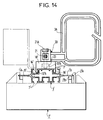
- Figure 14 shows that the distributor can be formed by adopting another type of profiles called linear profiles such as the profile shown and designated under the reference 1 '.
- This profile 1 ' already used for the constitution of a distributor, has several pairs of fins 7' on its front face and its rear face, the fins of each pair defining between them a housing 9 ', and with two branches 1' Projecting laterally, on both sides, for the attachment between them of each connection block 2 '.
- connection block 2 ' The pairs of fins on the front face serve as a stop for each connection block 2 ', fitted with elastic snap tabs 2'A and rigid stop tabs 2'B, on its rear mounting face, for hooking it on the branches 1'A.
- This profile 1 allows the traditional fixing of a cable channel guide trough on its rear face, such as the trough illustrated in dotted lines but not referenced, which is fixed on an L-shaped support, itself screwed to the pairs of 'fins on the rear side of the profile.
- This same profile also allows the fixing of the jumpers guide rings, such as the single horizontal guide ring shown in solid lines.
- This horizontal ring is identical to the 3A rings and designated by this reference. It is fixed to the profile 1 'by a fixing module 10'.
- This fixing module 10 ′ is analogous to the previous fixing module 10 in FIGS. 3 to 8, with a few differences which are only specified.
- the centering tabs 16 'of this fixing module each have a snap-on tooth 16'A, the two teeth being opposite and received in the two housings 9' of the rear face of the profile 1 'and s 'hanging under the two innermost fins of the rear face.
- This fixing module 10 ' has its endpiece engaged in the central part of the finger 30 of the guide ring 3A.
- the ring 3A is locked on the fixing module 10 ′, before this module clicks into place on the rear face of the profile.
- This blocking is ensured by a clamping screw 21 and a nut 23, square or rectangle, this nut being blocked, in rotation in the opening 13'A of the main centering face of the base of this module carrying the legs 16 '.
- This rear guide ring 3A on the profile 1 ' is offset laterally thereon, to make the garters, which it retains, accessible from the front of the distributor.
- the horizontal guide rings such as 3A can be alternately extend on one side and the other of this profile 1 ', to define two vertical paths along and on either side of the same profile 1 '. It is also indicated that vertical guide rings can be mounted at the bottom and / or at the top of the distributor, on the rear face of some of the profiles, to define a lower and / or upper horizontal path for the garters, in the distributor.
Abstract
Description
La présente invention porte sur un répartiteur téléphonique, comportant une série de profilés porteurs sur lesquels sont montés des équipements de raccordement, dits blocs de raccordement, et des équipements accessoires, tels que des anneaux de guidage de jarretières, en particulier.The present invention relates to a telephone distributor, comprising a series of carrier profiles on which are mounted connection equipment, said connection blocks, and accessory equipment, such as jumpers guide rings, in particular.
Ces blocs de raccordement sont reliés aux lignes de câbles dits d'entrée et de sortie à raccorder, ces câbles ou leurs lignes étant guidés et maintenus contre les profilés jusqu'au niveau sensiblement de chaque bloc de raccordement concerné. Ils se présentent en rangées, en face avant d'un répartiteur monoface, et reçoivent les jarretières en face avant, ces jarretières permettant un brassage des raccordements. Ils laissent entre leurs rangées ou toutes les deux rangées un espace libre dans lequel les anneaux de guidage des jarretières définissent un chemin de guidage, latéralement sur les rangées et en arrière des blocs de raccordements. Ces anneaux de guidage sont entrouverts en regard de la face avant du répartiteur et rendent les jarretières accessibles depuis la face avant.These connection blocks are connected to the so-called input and output cable lines to be connected, these cables or their lines being guided and held against the profiles up to the level substantially of each connection block concerned. They are presented in rows, on the front face of a single-sided distributor, and receive the garters on the front face, these garters allowing a patching of the connections. They leave between their rows or both rows a free space in which the guide rings of the jumpers define a guide path, laterally on the rows and behind the connection blocks. These guide rings are ajar opposite the front face of the distributor and make the garters accessible from the front face.
Ces anneaux de guidage sont d'axe parallèle aux profilés, pour le guidage de jarretières le long des rangées de blocs de raccordement, et peuvent en outre être pour certains d'entre eux d'axe transversal aux profilés pour le guidage supplémentaire de jarretières transversalement aux rangées de blocs de raccordement.These guide rings are of axis parallel to the profiles, for guiding jumpers along the rows of connection blocks, and may in addition be for some of them of axis transverse to the profiles for the additional guide of garters transversely. rows of terminal blocks.
Le document FR-A-2446040 décrit un tel répartiteur téléphonique. Dans ce répartiteur, les anneaux de guidage sont fixés sur des premiers profilés verticaux, à l'aide de pattes de fixation en forme de L. Les blocs de raccordement sont fixés sur des entretoises horizontales en U, elles-mêmes fixées sur les premiers profilés et saillantes à l'avant des anneaux, ou sont fixés sur des deuxièmes profilés verticaux situés à l'avant des premiers et leur étant assemblés par des entretoises horizontales en U. Les anneaux de guidage sont orientés convenablement sur les pattes de fixation pour leur orientation horizontale et verticale sur les premiers profilés verticaux. Les pattes de fixation sont quant à elles de deux longueurs différentes, selon l'orientation des anneaux, pour séparer l'un de l'autre le plan des chemins verticaux et le plan du ou des chemins horizontaux définis par les anneaux horizontaux et les anneaux verticaux.The document FR-A-2446040 describes such a telephone distributor. In this distributor, the guide rings are fixed on the first vertical profiles, using L-shaped fixing lugs. The connection blocks are fixed on horizontal U-shaped spacers, themselves fixed on the first profiles. and protruding at the front of the rings, or are fixed on second vertical profiles located at the front of the first and being assembled to them by horizontal U-shaped spacers. The guide rings are properly oriented on the fixing lugs for their horizontal and vertical orientation on the first vertical profiles. The fixing lugs are in turn of two different lengths, depending on the orientation of the rings, to separate from one another the plane of the vertical paths and the plane of the horizontal path or paths defined by the horizontal rings and the rings vertical.
Le répartiteur peut comporter de manière classique d'autres équipements accessoires, tels que notamment des tablettes support de câbles sur l'une et/ou l'autre des parties terminales des profilés, des marchepieds sur la partie terminale des profilés.The distributor may conventionally include other accessory equipment, such as in particular cable support shelves on one and / or the other of the terminal parts of the profiles, steps on the terminal part of the profiles.
Le document EP-A-0074898 décrit également un répartiteur de ce type, dans lequel les profilés portent l'ensemble des équipements pour l'organisation directe du répartiteur par colonne. Ces profilés présentent des paires d'ailettes sur leurs faces, pour le montage et le maintien des supports de fixation des équipements ou le maintien direct de certains équipements accessoires, tels que marchepieds, tablettes support de câbles, qui s'y prêtent. Les supports de fixation des équipements sont spécifiques à chaque type d'équipement et sont en général des plats en forme de U ou des pattes en équerre et de longueurs différentes. Ils sont eux-mêmes fixés sur les ailettes de la face avant des profilés ou entre les ailettes de leurs faces latérales, à l'aide d'une vis ou d'un jeu de vis traversant l'un de leurs jambages et ancrées dans les ailettes entre elles.The document EP-A-0074898 also describes a distributor of this type, in which the profiles carry all the equipment for the direct organization of the distributor by column. These profiles have pairs of fins on their faces, for mounting and maintaining the equipment mounting brackets or the direct support of certain accessory equipment, such as steps, cable support shelves, which lend themselves to it. The equipment mounting brackets are specific to each type of equipment and are generally U-shaped dishes or angled legs and different lengths. They are themselves fixed to the fins of the front face of the profiles or between the fins of their lateral faces, using a screw or a set of screws passing through one of their legs and anchored in the fins between them.
Les opérations de montage des équipements sur les profilés restent relativement longues pour la réalisation du répartiteur selon l'un ou l'autre de ces documents. Elles nécessitent en outre un nombre important de différents supports de fixation des équipements, qui se fixent différemment les uns des autres sur les profilés.The equipment mounting operations on the profiles remain relatively long for the realization of the distributor according to one or other of these documents. They also require a large number of different equipment fixing supports, which are fixed differently from each other on the profiles.
La présente invention a pour but de rationaliser la réalisation des répartiteurs, en minimisant les types de supports de fixation des divers équipements, et en rendant les opérations de montage aisées et rapides.The present invention aims to rationalize the production of distributors, by minimizing the types of mounting brackets for various equipment, and making assembly operations easy and quick.
Elle a pour objet un répartiteur téléphonique, comportant des profilés porteurs, alignés à la suite les uns des autres, des équipements de raccordement, dits blocs de raccordement, reliés à des lignes de câbles d'entrée et de sortie et à des jarretières, et des équipements accessoires, constitués pour au moins une partie d'entre eux par des anneaux de guidage des jarretières, et dans lequel lesdits profilés présentent des ailettes longitudinales de montage des équipements, lesdits blocs de raccordement forment des rangées parallèles aux profilés au moins sur une face avant du répartiteur et laissent au moins un accès latéral le long de chaque rangée, et lesdits anneaux de guidage maintenus sur lesdits profilés par des éléments individuels de fixation sont en regard des accès latéraux définis le long desdites rangées, caractérisé en ce que lesdits éléments de fixation sont des modules identiques et comportent chacun une embase plate, ayant deux faces principales, un embout, saillant sur une première des faces principales de l'embase, un alésage axial, traversant l'embase et l'embout et recevant une vis de serrage dans un écrou terminal associé, bloqué en rotation, et une paire de pattes saillantes sur la deuxième face principale de l'embase, pour le montage du module de fixation entre des ailettes des profilés, et en ce que lesdits anneaux de guidage comportent chacun un doigt latéral , pourvu d'un logement interne complémentaire de l'embout et débouchant sur l'extérieur du doigt d'une part par deux premières ouvertures orthogonales, d'insertion de l'embout dans ledit logement selon deux directions orthogonales, et d'autre part par deux deuxièmes ouvertures opposées auxdites premières ouvertures, de passage de ladite vis pour son serrage dans ledit écrou.It relates to a telephone distributor, comprising load-bearing profiles, aligned one after the other, connection equipment, called connection blocks, connected to input and output cable lines and to jumpers, and accessory equipment, consisting for at least part of them by guide rings of the garters, and in which said profiles have longitudinal fins for mounting the equipment, said connection blocks form rows parallel to the profiles at least on one front face of the distributor and leave at least one lateral access along each row, and said guide rings maintained on said profiles by individual fixing elements are opposite the lateral accesses defined along said rows, characterized in that said elements of fixing are identical modules and each have a flat base, having two faces main, an end piece, protruding on a first of the main faces of the base, an axial bore, passing through the base and the end piece and receiving a clamping screw in an associated terminal nut, locked in rotation, and a pair of lugs protruding on the second main face of the base, for mounting the fixing module between the fins of the profiles, and in that said guide rings each comprise a lateral finger, provided with an internal housing complementary to the end piece and opening on the outside of the finger on the one hand by two first orthogonal openings, insertion of the end piece in said housing in two orthogonal directions, and on the other hand by two second openings opposite to said first openings, for passage of said screw for tightening in said nut.
Le répartiteur présente de préférence en outre au moins l'une des caractéristiques additionnelles suivantes:
- ledit embout est de section droite sensiblement carrée et ledit logement de section analogue dans deux plans parallèles auxdites premières ouvertures, respectivement.
- lesdits anneaux de guidage sont identiques, de forme sensiblement rectangulaire et d'épaisseur suffisante pour leur résistance, ledit doigt latéral de chacun étant porté par un premier bord de l'anneau de guidage et étant sensiblement dans le prolongement d'un deuxième bord adjacent audit premier bord, et lesdites ouvertures dudit logement étant dans deux plans parallèles à la face extérieure dudit deuxième bord et dans deux plans parallèles au plan médian de l'anneau de guidage.
- ledit alésage de chaque module de fixation débouche dans un évidemment de la deuxième face principale de l'embase, ledit évidement étant de section sensiblement rectangulaire, supérieure à la section dudit alésage au niveau de la première face principale de ladite embase, et recevant sélectivement la tête de ladite vis, en la laissant libre en rotation, ou ledit écrou, en le bloquant en rotation.
- au moins une partie desdits anneaux de guidage est montée horizontalement relativement aux profilés, dits profilés verticaux, et les anneaux correspondants sont retenus chacun par l'un desdits modules de fixation sur l'une et l'autre des faces latérales d'une seule partie des profilés pour définir deux chemins verticaux de jarretières de part et d'autre de chacun d'eux.
- l'autre partie des anneaux de guidage est montée verticalement sur les profilés et les anneaux de cette autre partie sont retenus par l'un desdits modules de fixation sur l'une des faces latérales et avant de certains d'entre eux, pour définir au moins un chemin horizontal de jarretières.
- ledit embout des modules de fixation présente quatre fentes aux quatre coins de sa section carrée, devant l'embout et le rendant élastiquement déformable, et des chanfreins sur les extrémités de l'embout ainsi divisé.
- lesdits modules de fixation assurent la fixation de potences horizontales sur lesdits profilés et la fixation desdits blocs de raccordement sur le bout des potences et sont associés, à cet effet, chacun à une contre pièce de blocage alésée intérieurement et présentant une forme conique à section carrée extérieurement, s'engageant partiellement en force dans ledit embout, les profilés et les potences étant à section interne évidée et carrée et à section externe reliée à la section interne, en définissant des logements ouverts sur leurs faces périphériques chacun définie par une paire d'ailette longitudinales.
- said tip is of substantially square cross section and said housing of similar section in two planes parallel to said first openings, respectively.
- said guide rings are identical, of substantially rectangular shape and of sufficient thickness for their resistance, said lateral finger of each being carried by a first edge of the guide ring and being substantially in the extension of a second edge adjacent to said first edge, and said openings of said housing being in two planes parallel to the outer face of said second edge and in two planes parallel to the median plane of the guide ring.
- said bore of each fixing module opens into a recess in the second main face of the base, said recess being of substantially rectangular section, greater than the section of said bore at the level of the first main face of said base, and selectively receiving the head of said screw, leaving it free to rotate, or said nut, blocking it in rotation.
- at least a part of said guide rings is mounted horizontally relative to the profiles, called vertical profiles, and the corresponding rings are each retained by one of said fixing modules on one and the other of the lateral faces of a single part profiles to define two vertical paths of garters on either side of each of them.
- the other part of the guide rings is mounted vertically on the profiles and the rings of this other part are retained by one of said fixing modules on one of the lateral faces and before some of them, to define the minus a horizontal path of garters.
- said end piece of the fixing modules has four slots at the four corners of its square section, in front of the end piece and making it elastically deformable, and chamfers on the ends of the end piece thus divided.
- said fixing modules ensure the fixing of horizontal brackets on said profiles and the fixing said connection blocks on the end of the brackets and are associated, for this purpose, each with a blocking piece internally bored and having a conical shape with a square section externally, partially engaging in force in said end piece, the profiles and the gallows being of hollow and square internal section and of external section connected to the internal section, by defining open housings on their peripheral faces each defined by a pair of longitudinal fins.
Les caractéristiques et avantages de la présente invention ressortiront de la description faite ci-après, en référence aux dessins ci-annexés. Dans ces dessins:
- les figures 1 et 2 sont deux vues schématiques, en élévation et de côté, d'un répartiteur selon l'invention,
- les figures 3 et 4 sont deux vues frontales opposées, à échelle agrandie, d'un élément dit module de fixation des équipements du répartiteur de la figure 1,
- la figure 5 est une vue en coupe du module de fixation, faite selon la ligne V-V de la figure 4,
- la figure 6 est une vue de côté du module de fixation des figures 3 et 4,
- les figures 7 et 8 sont deux vues en coupe partielle du module de fixation, faite selon la ligne VII de la figure 3, montrant, à échelle agrandie, la partie concernée de ce module non équipée et équipée d'un insert, respectivement,
- la figure 9 est une vue en coupe, à échelle agrandie, selon la ligne IX-IX de la figure 2, montrant la fixation d'une potence sur un profilé porteur du répartiteur et d'un bloc de raccordement sur la potence,
- la figure 10 est une vue frontale d'une contre-pièce utilisée pour les fixations selon les figure 9 du bloc de raccordement, et de la potence,
- la figure 11 est une vue en coupe partielle et éclatée, à échelle agrandie, correspondant à la ligne XI-XI de la figure 1, montrant la fixation d'anneaux de guidage sur un profilé porteur du répartiteur,
- la figure 12 est une vue en coupe, selon la ligne XII-XII de la figure 11, de l'un des anneaux,
- la figure 13 est une vue en coupe à échelle agrandie, selon la ligne XIII-XIII de la figure 12, illustrant deux modes de montage de l'anneau.
- la figure 14 est une vue schématique de dessus d'une variante de constitution du répartiteur, donnée en regard de la figure 11 pour un autre type de profilé.
- FIGS. 1 and 2 are two schematic views, in elevation and from the side, of a distributor according to the invention,
- FIGS. 3 and 4 are two opposite front views, on an enlarged scale, of an element called a module for fixing the equipment of the distributor of FIG. 1,
- FIG. 5 is a sectional view of the fixing module, taken along the line VV of FIG. 4,
- FIG. 6 is a side view of the fixing module of FIGS. 3 and 4,
- FIGS. 7 and 8 are two views in partial section of the fixing module, made along line VII of FIG. 3, showing, on an enlarged scale, the part concerned of this module not equipped and equipped with an insert, respectively,
- FIG. 9 is a sectional view, on an enlarged scale, along the line IX-IX of FIG. 2, showing the fixing of a bracket on a support profile of the distributor and of a connection block on the bracket,
- FIG. 10 is a front view of a counter-piece used for the fastenings according to FIG. 9 of the connection block, and of the bracket,
- FIG. 11 is a partial and exploded sectional view, on an enlarged scale, corresponding to the line XI-XI of FIG. 1, showing the fixing of guide rings on a support profile of the distributor,
- FIG. 12 is a sectional view, along the line XII-XII of FIG. 11, of one of the rings,
- Figure 13 is a sectional view on an enlarged scale, along the line XIII-XIII of Figure 12, illustrating two modes of mounting the ring.
- Figure 14 is a schematic top view of a variant construction of the distributor, given with reference to Figure 11 for another type of profile.
Le répartiteur illustré dans les figures 1 et 2 est monoface. Il peut tout aussi bien, en variante, être double face.The distributor shown in Figures 1 and 2 is single sided. Alternatively, it can also be double-sided.
Ce répartiteur comprend une série de profilés porteurs 1, identiques et alignés, sur lesquels sont montés des équipements de raccordement 2, dits blocs de raccordement, et des équipements accessoires constitués essentiellement par des anneaux de guidage 3A et 3B, seuls représentés et affectés au guidage de jarretières. Il est décrit en considérant les profilés 1 verticaux, comme ceci est le cas général, mais ces profilés 1 peuvent tout aussi bien être horizontaux.This distributor includes a series of
Les blocs de raccordement 2 sont fixés en bout de potences horizontales 4, elles-mêmes fixées sur les profilés 1 et appartenant avec ces profilés à la structure porteuse. Ils sont reliés aux lignes d'entrée d'un ou de plusieurs câbles d'entrée, pour certains d'entre eux, et aux lignes de sortie d'un ou de plusieurs câbles de sortie pour les autres, ces câbles ou leurs lignes non représentés étant guidés le long des profilés depuis l'une et/ou l'autre de leurs extrémités où les câbles sont retenus.The connection blocks 2 are fixed at the end of
Les jarretières, non représentées, sont guidées par les anneaux de guidage 3A parallèlement aux profilés 1, ces anneaux 3A étant horizontaux, et par les anneaux de guidage 3B transversalement aux profilés 1, ces anneaux 3B étant verticaux. Elles sont reliées aux blocs de raccordement 2 en face avant du répartiteur ou des blocs de raccordement sur la structure porteuse, pour les raccordements des lignes d'entrée aux lignes de sortie et le brassage possible de ces raccordements.The garters, not shown, are guided by the guide rings 3A parallel to the
Les anneaux de guidage 3A sont le long des profilés 1. Les anneaux de guidage 3B sont à un ou à des niveaux horizontaux définis, en particulier au niveau inférieur du répartiteur.The guide rings 3A are along the
Les profilés porteurs 1 sont maintenus les uns relativement aux autres par des entretoises horizontales 5 d'assemblage. Ces entretoises sont des plats qui assurent également dans cet exemple de réalisation la fixation du répartiteur. Elles présentent à cet effet leurs portions terminales 5A, coudées à angle droit et saillantes sur l'avant du répartiteur, dans lesquelles sont prévus des trous 5B, pour leur fixation par vis à des parois latérales ou flancs du répartiteur. Elles peuvent également ou en variante être fixées de manière analogue à une paroi arrière ou à un mur. Le répartiteur peut en variante être fixé au sol et relativement au plafond d'un local.The
Les profilés 1 sont du type standard utilisé en particulier dans le domaine de la robotique pour la constitution de châssis de machines spéciales d'assemblage. Les potenses 4 sont des tronçons de profilé choisi identique aux profilés 1.
La section des profilés 1 est visible dans la figure 11. Ces profilés 1 sont décrits immédiatement ci-après, en se référant plus particulièrement à cette figure 11.The section of the
Ils comportent quatre joues internes 6, définissant entre elles une section interne évidée 6A, sensiblement carrée, quatre paires d'ailettes extérieures 7, définissant entre elles une section externe également sensiblement carrée, dont les côtés sont parallèles aux côtés de la section interne et de longueur sensiblement double, et quatre entretoises 8, reliant les joues internes et les ailettes et s'étendant selon les diagonales des sections interne et externe. Chaque paire d'ailettes, la joue interne en vis-à-vis et les deux entretoises latérales correspondantes délimitent entre elles un logement 9 le long de chaque face du profilé. Chaque logement 9 a une ouverture médiane 9A définie entre les deux ailettes extérieures de chaque face du profilé.They comprise four
Les potences 4 sont identiques aux profilés, leurs parties étant simplement désignées par les références de celles des profilés.The
En se référant à nouveau à la figure 1 ou 2, on voit que des éléments de fixation 10, tous identiques et dits modules de fixation, assurent la fixation des potences 4 et des anneaux de guidage 3A et 3B sur les profilés 1 et celle des blocs de raccordement 2 en bout des potences. On voit aussi que les blocs de raccordement 2 montés sur les profilés forment des rangées parallèles en face avant du répartiteur. Ils laissent un intervalle d'accès entre les rangées, ou en variante toutes les deux rangées. Les anneaux de guidage 3A et 3B montés sur les profilés sont à l'arrière des blocs de raccordement et en regard de ces intervalles d'accès. Ils définissent entre eux les chemins de jarretières, les jarretières étant reliées aux blocs de raccordement sur leur face avant.Referring again to FIG. 1 or 2, it can be seen that fixing
Les anneaux de guidage 3A sont horizontaux et définissent un chemin de guidage latéral le long de chaque rangée. Ils sont de préférence regroupés sur certains profilés 1, en définissant deux chemins verticaux de part et d'autre de chaque profilé concerné.The guide rings 3A are horizontal and define a lateral guide path along each row. They are preferably grouped together on
Les anneaux de guidage 3B sont verticaux et définissent de préférence un chemin de guidage inférieur horizontal ou pareillement un chemin de guidage supérieur horizontal. Chaque chemin de guidage horizontal est à l'arrière des blocs de raccordement. Il est rendu décalé relativement aux chemins verticaux directement par le mode de montage des anneaux 3A et 3B concernés sur chacun des modules de fixation.The guide rings 3B are vertical and preferably define a horizontal lower guide path or similarly a horizontal upper guide path. Each horizontal guide path is at the rear of the connection blocks. It is made offset relative to the vertical paths directly by the mounting mode of the
Les modules de fixation 10 sont décrits en regard des figures 3 à 7.The fixing
Chacun d'eux comporte une embase 11, relativement plate, dont les faces opposées principales sont sensiblement carrées et sont de côté sensiblement égal au côté de la section externe des profilés, et un embout 12, saillant sur l'une des deux faces principales de l'embase et centrée sur cette face principale. Chacun présente un alésage axial 13 traversant l'embase et l'embout.Each of them has a relatively
L'embout 12 est de section droite sensiblement carrée, qui est tronquée par des fentes 14 le long de ses arêtes. Ces fentes 14 divisent l'embout en quatre ailettes notées 15 et rendues légèrement élastiques. Les faces intérieures 15A des ailettes 15 sont chanfreinées le long des fentes, ainsi que le bord terminal 15B des faces extérieures des ailettes.The
Ce module de fixation présente deux pattes opposées de centrage 16, saillantes sur l'autre face principale de l'embase, dite face de centrage. Ces pattes sont centrées sur deux des côtés opposés de la face de centrage. Elles sont droites et chacune de longueur sensiblement égale à la largeur de l'ouverture longitudinale 9A entre les ailettes externes 7 des profilés 1 et des potences 4.This fixing module has two opposite centering
Ce module comporte en outre quatre trous débouchants 17, prévus à proximité des quatre coins de l'embase, et quatre empreintes ou cavités 18, prévues entre les trous 17, sur la face principale portant l'embout.This module further comprises four through
L'alésage axial 13 est de section carrée le long de l'embout, de section circulaire dans la partie de jonction de l'embout sur l'embase, cette section circulaire s'inscrivant dans la section carrée le long de l'embout. Il débouche ensuite dans une ouverture rectangulaire 13A, de section supérieure, du côté de la face de centrage de l'embase. Deux empreintes en vis-à-vis 13B, semi-circulaires et centrées sur les deux grands bords de cette ouverture 13A définissent entre elles, dans cette ouverture, le logement possible pour une tête de vis.The
Les modules de fixation 10 sont relativement rigides, exception faite de l'embout rendu élastique par ses quatre fentes longitudinales. Ils sont de préférence en matière plastique et réalisés par moulage.The fixing
Les trous 17 dans l'embase sont précisés en regard des figures 8 et 9. Chacun est divisé en trois parties 17A, 17B et 17C à la suite. La partie terminale 17A sur la face de centrage de l'embase et la partie intermédiaire 17B sont de section circulaire. La partie terminale 17C sur la face principale portant l'embout est de section carrée. Le diamètre de la partie terminale 17A est légèrement inférieur à celui de la partie intermédiaire, lui même légèrement inférieur au côté de la partie 17C.The
Ainsi que représenté dans la figure 8, considérée relativement à la figure 7, un insert métallique 19, tubulaire et fileté intérieurement, est monté dans chaque trou 17, pour renforcer la résistance d'une fixation réalisée par des vis bloquées dans ces trous 17 ainsi équipés. Cet insert introduit par la partie 17C a son extrémité avant venant en butée contre l'épaulement annulaire 17D défini entre les parties 17A et 17B. Il présente pour son propre blocage dans le trou, un épaulement arrière 19A, venant en butée contre l'épaulement annulaire 17E défini entre les parties 17B et 17C, et une dent annulaire périphérie 19B ancrée dans le bord de la partie intermédiaire 17B.As shown in FIG. 8, considered relative to FIG. 7, a
La figure 9 montre l'une des potences 4 fixée à l'un des profilés 1 et équipée pour pouvoir y fixer en bout un bloc de raccordement. Ces deux fixations sont assurées par deux modules de fixation 10, à chacun desquels sont associés une contre pièce de blocage 20, une vis de serrage 21 à tête 21A et un écrou 22 ou 23.Figure 9 shows one of the
La contre pièce de blocage 20 est reçue partiellement dans l'embout 12 du module de fixation. Elle est de forme conique extérieurement. Sa section droite est carrée sensiblement à coins arrondis ainsi qu'il ressort de la figure 10. Sa petite base 20A est de côté plus petit que celui de la section droite de l'alésage 13 de l'embout et sa grande base 20B de côté plus grand et au moins égal à celui de la section droite de l'embout. Elle présente un trou axial 20C de section droite circulaire, qui correspond à celle de la partie circulaire de l'alésage 13 à la jonction de l'embase et de l'embout.The
L'écrou 22 est rhomboïdal. Il est relativement plat et a ses deux faces frontales en forme de parallélogramme, sensiblement. Ses dimensions sont telles qu'il s'engage dans l'un des logements 9 du profilé 1 directement à travers l'ouverture 9A et se bloque dans ce logement par rotation d'un quart de trou.The
L'écrou 23 est de section carrée non tronquée, qui correspond sensiblement à la section interne des potences, dans laquelle il est enfilé et se bloque en rotation.The
La fixation de la potence 4 sur le profilé 1 se fait en insérant tout d'abord la contre pièce de blocage 20 dans l'embout 12 puis la vis 21 dans le trou 20C et la partie de l'alésage 13 prolongeant le trou 20C dans l'embase 11, jusqu'à butée de la tête 21A contre la grande base 20B de la contre pièce de blocage 20. L'écrou rhomboïdal 22 est alors vissé sans serrage sur l'extrémité de la vis. Le module de fixation 10 ainsi équipé est enfilé dans l'une des deux extrémités de la potence 4, avec la tête 21A de la vis 21 et l'embout venant se loger dans la section interne de la potence, jusqu'à butée de l'embase contre le bout de la potence. L'écrou 22 est lui même engagé dans le logement 9 de la face avant du profilé, tout en maintenant l'embase 12 du module de fixation contre le bout de la potence et en engageant les pattes de centrage 16 dans l'ouverture 9A du logement. On serre alors, à l'aide d'un tournevis, depuis l'autre extrémité de la potence 4, la vis sur l'écrou 22, ce qui donne lieu tout d'abord à la rotation quart de tour de l'écrou pour son blocage en rotation, puis à l'avance de la contre pièce de blocage dans l'embout et à la déformation des ailettes élastiques 15 de l'embout jusqu'à obtenir le blocage résultant de l'embout 12 et donc du module de fixation 10 dans la potence et sur le profilé.The
Le montage du module de fixation 10 sur l'autre extrémité libre de la potence se fait de manière comparable, mais cette fois en enfilant l'écrou carré 23, monté sur la vis 21 du module équipé, dans la section interne de la potence 4. On serre alors la vis 21 en actionnant sa tête 21A, qui est cette fois accessible sur le bout de la potence, pour l'avance de la contre-pièce 20 dans l'embout et le blocage résultant de ce module de fixation sur la potence.The mounting of the fixing
L'embase de ce dernier module de fixation 10 bouche l'extrémité avant de la potence. Deux modules de fixation 10, fixés sur le bout avant de deux potences successives sur l'un des profilés 1, permettent de venir fixer un des blocs de raccordement 2 entre eux. Cette fixation est assurée par des vis 25 insérées dans deux des quatre trous 17 de l'embase de chacun de ces deux modules de fixation. Ces deux modules de fixation sont alors en butée contre les deux pattes de centrage 16 du module de fixation qui leur est commun.The base of the
La figure 11 montre la fixation de deux anneaux de guidage horizontaux 3A sur l'un des profilés 1.FIG. 11 shows the fixing of two horizontal guide rings 3A on one of the
La fixation de chacun de ces deux anneaux de guidage 3A est assurée par l'un des modules de fixation 10 auquel sont associés une vis de serrage et un écrou rhomboïdal, désignés par leurs références respectives précédentes 21 et 22, mais pas la contre-pièce de blocage rendue non nécessaire.The fixing of each of these two
Pour cette fixation, ainsi que visible plus particulièrement sur l'anneau de guidage 3A de droite, non monté en place, chaque anneau de guidage est pourvu d'un doigt latéral de montage 30, qui est saillant sur l'arrière de l'anneau de guidage, et ce doigt comporte un logement 34 qui permet d'enfiler le doigt sur l'embout 12 du module de fixation et la vis de serrage 21 dans l'alésage de l'embout.For this fixing, as can be seen more particularly on the
Le doigt 30 étant enfilé sur l'embout et la vis dans l'alésage 13 avec sa tête 21A en butée contre le doigt, on monte l'écrou rhomboïdal 22 sur le bout de la vis. On insère alors l'écrou dans le logement 9 de l'une des deux faces latérales du profilé 1 et les pattes de centrage 16 dans l'ouverture de ce logement, tout en maintenant le doigt 30 sur l'embout et donc l'anneau sur le module de fixation. On serre ensuite la vis sur l'écrou 22, bloqué dès sa rotation d'un quart de trou dans son logement, par action sur la tête 21A située sur le côté extérieur.The
Le montage des deux anneaux de guidage 3A, horizontalement, sur l'une et l'autre des deux faces latérales du profilé 1, est rendu possible par des dispositions prévues sur chaque anneau de guidage 3A et plus précisément sur son doigt 30.The mounting of the two guide rings 3A, horizontally, on one and the other of the two lateral faces of the
L'anneau de guidage 3A et son doigt 30 sont décrits en détail en se référant à cette figure 11 et aux figures 12 et 13.The
L'anneau de guidage 3A est de forme rectangulaire, à coins arrondis et d'épaisseur suffisante pour sa résistance. Il est en plastique et réalisé par moulage.The
Le doigt 30 est formé sensiblement à la jonction entre le grand bord dit arrière, pour les conditions de montage et d'utilisation de l'anneau de guidage 3A, et l'un des deux autres bords dits latéraux. Il est saillant sur l'arrière de l'anneau en étant perpendiculaire à ce bord longitudinal arrière, à l'une des extrémités de celui-ci sensiblement.The
Les bords de l'anneau sont de section droite en I, pour une rigidité de l'anneau, le jambage central du I étant dans le plan médian de symétrie de l'anneau.The edges of the ring are of cross section in I, for a rigidity of the ring, the central leg of the I being in the median plane of symmetry of the ring.
Le bord avant opposé à celui portant le doigt 30 présente une ouverture 31, d'entrée et de sortie des jarretières. Cette ouverture n'est pas centrée sur le bord avant mais très légèrement décalée vers l'extrémité de ce bord qui est diagonalement opposée au point de départ du doigt sur le bord arrière. Elle est en biais, avec son extrémité extérieure sur l'anneau plus proche du centre du bord avant que son extrémité intérieure. Elle est limitée de part et d'autre par deux facettes en biais 31A, 31B, pleines et parallèles, la facette 31A la plus proche du centre du bord avant étant plus longue que l'autre et légèrement saillante dans l'anneau, en formant un bec 31C s'opposant à la sortie naturelle des jarretières de l'anneau de guidage.The front edge opposite to that carrying the
Le doigt 30 est divisé en une patte 32, d'attache au bord arrière, et en une partie terminale 33, de montage sur le module de fixation.The
La patte 32 est de même épaisseur que l'anneau de guidage. Elle est également de section en I, dont le jambage médian 32A est dans le plan médian de symétrie de l'anneau, et les jambages 32B et 32C sont perpendiculaires au bord arrière de l'anneau, le jambage 32B partant de l'extrémité de ce bord arrière et étant dit jambage latéral extérieur de la patte, l'autre jambage 32C étant dit jambage latéral intérieur, par opposition au précédent.The
La partie terminale 33 a une forme de pavé parallélépipédique et est ainsi appelée. Ce pavé est évidé pour définir le logement 34, sensiblement cubique, de côté correspondant à celui de la section droite de l'embout 12 du module de fixation 10. Il reçoit l'embout 12 selon deux directions orthogonales possibles FA et FB ainsi qu'illustré dans la figure 13. Le logement est à cet effet totalement ouvert sur deux faces adjacentes du pavé, autres que celle frontale du pavé et celle opposée de jonction avec la patte 32. L'une des faces totalement ouverte 33B est celle dite latérale extérieure du pavé, qui est coplanaire avec le jambage latéral extérieur de la patte. L'autre 33A est l'une des faces parallèles au plan médian de l'anneau de guidage. Ce logement 33 est en outre ouvert sur les faces opposées aux faces 33B et 33A, pour le passage de la vis de serrage précitée dans l'alésage de l'embout du module de fixation, quand cet embout est enfilé dans le logement 34 avec l'une de ses deux directions possibles FB et FA par l'une des faces 33B et 33A. Il présente à cet effet une ouverture 34A opposée à la face totalement ouverte 33A et une ouverture 34B opposée à la face totalement ouverte 33B.The
En se référant à la figure 11, on précise que ce logement 34 et les dispositions prévues, pour enfiler selon deux directions possibles l'embout 12 dans le logement et la vis de blocage dans l'embout et le pavé, permettent de monter les anneaux horizontaux de guidage 3A sur l'une et l'autre des deux faces latérales du profilé 1. Les jarretières guidées dans deux séries d'anneaux le long et de part et d'autre de ce profilé peuvent desservir la série de blocs de raccordement sur ce même profilé et au moins l'une des deux séries adjacentes de blocs de raccordement montés sur les deux profilés de part et d'autre de celui considéré.Referring to FIG. 11, it is specified that this
Les figures 2 et 3 montrent également un anneau de guidage 3B vertical, monté sur l'un des profilés 2. Cet anneau de guidage 3B est monté au bas de ce profilé pour définir avec d'autres anneaux verticaux montés de la même manière sur d'autres profilés un chemin de guidage horizontal au niveau inférieur du répartiteur.Figures 2 and 3 also show a
Cet anneau de guidage 3B est identique aux anneaux de guidage 3A et est fixé de manière analogue à ces derniers sur le profilé par l'un des modules de fixation 10, auquel sont associés la vis de serrage et l'écrou rhomboïdal précités. Il est illustré fixé sur la face avant du profilé, le petit bord de l'anneau 3B proche du doigt 30 devenant alors le bord arrière situé en regard de la face avant du profilé. Dans ces conditions de montage de l'anneau 3B sur la face avant du profilé, l'axe médian de l'anneau 3B est plus à l'avant du profilé que les axes médians des anneaux 3A.This
En variante l'anneau de guidage 3B peut être fixé sur l'une des deux faces latérales du profilé au bas celui-ci. Dans ces conditions le chemin horizontal défini par les anneaux 3B n'est pas décalé à l'avant des profilés, par rapport aux chemins verticaux, mais simplement en dessous de ces chemins verticaux.As a variant, the
La figure 14 montre que le répartiteur peut être constitué en adoptant un autre type de profilés dits profilés linéaires tels que le profilé représenté et désigné sous la référence 1'. Ce profilé 1', déjà utilisé pour la constitution de répartiteur, est à plusieurs paires d'ailettes 7' sur sa face avant et sa face arrière, les ailettes de chaque paire définissant entre elles un logement 9', et à deux branches 1'A saillantes latéralement, de part et d'autre, pour l'accrochage entre elles de chaque bloc de raccordement 2'.Figure 14 shows that the distributor can be formed by adopting another type of profiles called linear profiles such as the profile shown and designated under the reference 1 '. This profile 1 ', already used for the constitution of a distributor, has several pairs of fins 7' on its front face and its rear face, the fins of each pair defining between them a housing 9 ', and with two branches 1' Projecting laterally, on both sides, for the attachment between them of each connection block 2 '.
Les paires d'ailettes de la face avant servent de butée pour chaque bloc de raccordement 2', équipé de pattes élastiques d'encliquetage 2'A et de pattes rigides de butée 2'B, sur sa face arrière de montage, pour son accrochage sur les branches 1'A.The pairs of fins on the front face serve as a stop for each connection block 2 ', fitted with elastic snap tabs 2'A and rigid stop tabs 2'B, on its rear mounting face, for hooking it on the branches 1'A.
Ce profilé 1' permet la fixation traditionnelle d'une goulotte de guidage des lignes des câbles sur sa face arrière, telle que la goulotte illustrée en pointillés mais non référencée, qui est fixée sur un support en L, lui-même vissé aux paires d'ailettes de la face arrière du profilé.This profile 1 'allows the traditional fixing of a cable channel guide trough on its rear face, such as the trough illustrated in dotted lines but not referenced, which is fixed on an L-shaped support, itself screwed to the pairs of 'fins on the rear side of the profile.
Ce même profilé permet également la fixation des anneaux de guidage de jarretières, tel que du seul anneau horizontal de guidage représenté en trait plein. Cet anneau horizontal est identique aux anneaux 3A et désigné par cette référence. Il est fixé sur le profilé 1' par un module de fixation 10'. Ce module de fixation 10' est analogue au module de fixation précédent 10 des figures 3 à 8, à quelques différences près qui sont seules précisées.This same profile also allows the fixing of the jumpers guide rings, such as the single horizontal guide ring shown in solid lines. This horizontal ring is identical to the 3A rings and designated by this reference. It is fixed to the profile 1 'by a fixing module 10'. This fixing
Les pattes de centrage 16' de ce module de fixation ont chacune une dent d'encliquetage 16'A, les deux dents étant en vis-à-vis et reçues dans les deux logements 9' de la face arrière du profilé 1' et s'accrochant sous les deux ailettes les plus intérieures de la face arrière.The centering tabs 16 'of this fixing module each have a snap-on tooth 16'A, the two teeth being opposite and received in the two housings 9' of the rear face of the profile 1 'and s 'hanging under the two innermost fins of the rear face.
Ce module de fixation 10' a son embout engagé dans la partie centrale du doigt 30 de l'anneau de guidage 3A. L'anneau 3A est bloqué sur le module de fixation 10', avant l'encliquetage de ce module sur la face arrière du profilé. Ce bloquage est assuré par une vis de serrage 21 et un écrou 23, carré ou rectangle, cet écrou étant bloqué, en rotation dans l'ouverture 13'A de la face principale de centrage de l'embase de ce module portant les pattes 16'.This fixing module 10 'has its endpiece engaged in the central part of the
Cet anneau de guidage 3A arrière sur le profilé 1' est décalé latéralement sur celui-ci, pour rendre les jarretières, qu'il retient, accessibles depuis l'avant du répartiteur.This
Bien que non représenté sur cette figure 14, on indique que les anneaux horizontaux de guidage tels que 3A peuvent être alternativement s'étendre d'un côté et de l'autre de ce profilé 1', pour définir deux chemins verticaux le long et de part et d'autre du même profilé 1'. On indique également que des anneaux verticaux de guidage peuvent être montés au bas et/ou au haut du répartiteur, sur la face arrière de certains des profilés, pour définir un chemin horizontal inférieur et/ou supérieur pour les jarretières, dans le répartiteur.Although not shown in this figure 14, it is indicated that the horizontal guide rings such as 3A can be alternately extend on one side and the other of this profile 1 ', to define two vertical paths along and on either side of the same profile 1 '. It is also indicated that vertical guide rings can be mounted at the bottom and / or at the top of the distributor, on the rear face of some of the profiles, to define a lower and / or upper horizontal path for the garters, in the distributor.
Claims (17)
Applications Claiming Priority (2)
| Application Number | Priority Date | Filing Date | Title |
|---|---|---|---|
| FR9309226A FR2708405B1 (en) | 1993-07-27 | 1993-07-27 | Telephone distributor. |
| FR9309226 | 1993-07-27 |
Publications (1)
| Publication Number | Publication Date |
|---|---|
| EP0637178A1 true EP0637178A1 (en) | 1995-02-01 |
Family
ID=9449672
Family Applications (1)
| Application Number | Title | Priority Date | Filing Date |
|---|---|---|---|
| EP94401701A Withdrawn EP0637178A1 (en) | 1993-07-27 | 1994-07-25 | Telephone distribution frame |
Country Status (2)
| Country | Link |
|---|---|
| EP (1) | EP0637178A1 (en) |
| FR (1) | FR2708405B1 (en) |
Cited By (5)
| Publication number | Priority date | Publication date | Assignee | Title |
|---|---|---|---|---|
| EP0851254A1 (en) * | 1996-12-31 | 1998-07-01 | Siecor Corporation | Routing and storage apparatus for optical fibers |
| WO2001074091A2 (en) * | 2000-03-28 | 2001-10-04 | Panduit Corp. | Cable manager for network rack |
| US7000784B2 (en) | 2003-03-07 | 2006-02-21 | Panduit Corp. | Rack-mountable cable manager |
| US7756190B2 (en) | 1995-06-30 | 2010-07-13 | Interdigital Technology Corporation | Transferring voice and non-voice data |
| WO2017103394A1 (en) * | 2015-12-17 | 2017-06-22 | Legrand France | Device for guiding orientable cables |
Citations (2)
| Publication number | Priority date | Publication date | Assignee | Title |
|---|---|---|---|---|
| FR2102560A5 (en) * | 1970-08-07 | 1972-04-07 | Cit Alcatel | |
| WO1990004313A1 (en) * | 1988-10-05 | 1990-04-19 | Australian Telecommunications Corporation | Main distribution frame structure |
-
1993
- 1993-07-27 FR FR9309226A patent/FR2708405B1/en not_active Expired - Fee Related
-
1994
- 1994-07-25 EP EP94401701A patent/EP0637178A1/en not_active Withdrawn
Patent Citations (2)
| Publication number | Priority date | Publication date | Assignee | Title |
|---|---|---|---|---|
| FR2102560A5 (en) * | 1970-08-07 | 1972-04-07 | Cit Alcatel | |
| WO1990004313A1 (en) * | 1988-10-05 | 1990-04-19 | Australian Telecommunications Corporation | Main distribution frame structure |
Cited By (11)
| Publication number | Priority date | Publication date | Assignee | Title |
|---|---|---|---|---|
| US7756190B2 (en) | 1995-06-30 | 2010-07-13 | Interdigital Technology Corporation | Transferring voice and non-voice data |
| EP0851254A1 (en) * | 1996-12-31 | 1998-07-01 | Siecor Corporation | Routing and storage apparatus for optical fibers |
| USRE41353E1 (en) | 1999-03-03 | 2010-05-25 | Panduit Corp. | Cable manager for network rack |
| WO2001074091A2 (en) * | 2000-03-28 | 2001-10-04 | Panduit Corp. | Cable manager for network rack |
| WO2001074091A3 (en) * | 2000-03-28 | 2002-10-10 | Panduit Corp | Cable manager for network rack |
| US6766093B2 (en) | 2000-03-28 | 2004-07-20 | Panduit Corp. | Cable manager for network rack |
| KR100730622B1 (en) * | 2000-03-28 | 2007-06-20 | 팬듀트 코포레이션 | Cable manager for network rack |
| US7000784B2 (en) | 2003-03-07 | 2006-02-21 | Panduit Corp. | Rack-mountable cable manager |
| US7378046B2 (en) | 2003-03-07 | 2008-05-27 | Panduit Corp. | Method of molding rack-mountable cable manager |
| WO2017103394A1 (en) * | 2015-12-17 | 2017-06-22 | Legrand France | Device for guiding orientable cables |
| FR3045969A1 (en) * | 2015-12-17 | 2017-06-23 | Legrand France | ORIENTABLE CABLES GUIDING DEVICE |
Also Published As
| Publication number | Publication date |
|---|---|
| FR2708405A1 (en) | 1995-02-03 |
| FR2708405B1 (en) | 1995-09-01 |
Similar Documents
| Publication | Publication Date | Title |
|---|---|---|
| EP0866531B1 (en) | Redundant corner connection for a metal support, especially for a frame for an electric cabinet | |
| CH631062A5 (en) | WALL EXHIBITION DEVICE. | |
| FR3019862A1 (en) | SYSTEM FOR ASSEMBLING PANELS FOLLOWING A DIEDRE FOR MAKING A FURNITURE AND FURNITURE SO PRODUCED | |
| EP0143718A2 (en) | Housing for an electrical apparatus suitable for assembly at the moment of installation | |
| EP0637178A1 (en) | Telephone distribution frame | |
| FR2477215A1 (en) | Extending gate or fence panel frame - has common grid for gate and fence with mounting bolts or plates and telescopic tubular beams | |
| FR3090807A1 (en) | CONNECTION SYSTEM AND PERGOLA COMPRISING SAID CONNECTION SYSTEM | |
| EP3351811A1 (en) | Assembly kit for support structures, assembly method and support structures assembled using said assembly kit | |
| EP0235060A1 (en) | Connection device for assembling beams, and wood construction made by the use of such a connection device | |
| FR2839209A1 (en) | Corner fixing unit for housing frames and housings for telecoms and switch cabinets has sections interlocking at right angles and locked by a pin | |
| FR2727577A1 (en) | Four face electrical supply, control and distribution for housing cables for supply or lighting | |
| FR3059026B1 (en) | PROFILE HEAD FOR MULTI-ANGLE FENCE | |
| EP0637177B1 (en) | Telephone distributing frame column | |
| FR2671385A1 (en) | Component for assembling long straight elements | |
| FR2875389A3 (en) | Dismantlable garden plant stand has uprights and shelves, side bars supporting uprights which have vertical bores in their ends, through which uprights pass, and which are extended by threaded collars with locking sleeves | |
| EP1544478B1 (en) | Assembly of a pipe clamp | |
| FR2896632A1 (en) | Cabinet parallelepiped frame for electrical apparatus, has lower and upper frames formed of assembly of cross-pieces, where cross pieces and interlocking section are assembled by respective external and internal soldering | |
| EP2314887B1 (en) | Device for attaching, to a bearing structure, the flat junction of a plurality of adjacent panels | |
| FR2865510A1 (en) | REVERSIBLE SOLIDARIZATION ELEMENT, PANELS AND STORAGE HAVING SUCH ELEMENTS | |
| CH689985A5 (en) | guide device and assembly for the execution of various jobs. | |
| FR2675961A1 (en) | EXTENSION FOR ELECTRICAL BOX. | |
| FR2762152A1 (en) | DEVICE FOR ATTACHING AN OMNIBUS BAR TO A SET OF OMNIBUS BARS | |
| FR3097693A1 (en) | Assembly device and electrical cabinet frame comprising such a device | |
| CH665106A5 (en) | MODULAR STRUCTURE FOR THE PRODUCTION OF FURNITURE. | |
| FR2659402A1 (en) | CORNER PIECE FOR ASSEMBLING THE SIDES OF A FRAME AND DEVICE FOR ASSEMBLING MULTIPLE FRAMES. |
Legal Events
| Date | Code | Title | Description |
|---|---|---|---|
| PUAI | Public reference made under article 153(3) epc to a published international application that has entered the european phase |
Free format text: ORIGINAL CODE: 0009012 |
|
| AK | Designated contracting states |
Kind code of ref document: A1 Designated state(s): DE FR GB IT SE |
|
| 17P | Request for examination filed |
Effective date: 19950629 |
|
| GRAG | Despatch of communication of intention to grant |
Free format text: ORIGINAL CODE: EPIDOS AGRA |
|
| 17Q | First examination report despatched |
Effective date: 19981014 |
|
| STAA | Information on the status of an ep patent application or granted ep patent |
Free format text: STATUS: THE APPLICATION HAS BEEN WITHDRAWN |
|
| 18W | Application withdrawn |
Withdrawal date: 19990407 |