EP0637012A2 - Appareil de réduction de bruit - Google Patents
Appareil de réduction de bruit Download PDFInfo
- Publication number
- EP0637012A2 EP0637012A2 EP94108160A EP94108160A EP0637012A2 EP 0637012 A2 EP0637012 A2 EP 0637012A2 EP 94108160 A EP94108160 A EP 94108160A EP 94108160 A EP94108160 A EP 94108160A EP 0637012 A2 EP0637012 A2 EP 0637012A2
- Authority
- EP
- European Patent Office
- Prior art keywords
- noise
- signal
- output
- voice
- cancel
- Prior art date
- Legal status (The legal status is an assumption and is not a legal conclusion. Google has not performed a legal analysis and makes no representation as to the accuracy of the status listed.)
- Granted
Links
Images


Classifications
-
- G—PHYSICS
- G10—MUSICAL INSTRUMENTS; ACOUSTICS
- G10L—SPEECH ANALYSIS OR SYNTHESIS; SPEECH RECOGNITION; SPEECH OR VOICE PROCESSING; SPEECH OR AUDIO CODING OR DECODING
- G10L15/00—Speech recognition
- G10L15/02—Feature extraction for speech recognition; Selection of recognition unit
-
- G—PHYSICS
- G10—MUSICAL INSTRUMENTS; ACOUSTICS
- G10L—SPEECH ANALYSIS OR SYNTHESIS; SPEECH RECOGNITION; SPEECH OR VOICE PROCESSING; SPEECH OR AUDIO CODING OR DECODING
- G10L21/00—Processing of the speech or voice signal to produce another audible or non-audible signal, e.g. visual or tactile, in order to modify its quality or its intelligibility
- G10L21/02—Speech enhancement, e.g. noise reduction or echo cancellation
- G10L21/0208—Noise filtering
- G10L21/0216—Noise filtering characterised by the method used for estimating noise
- G10L21/0232—Processing in the frequency domain
Definitions
- the present invention relates to a signal processing device for eliminating effectively a noise from a signal containing a noise such as a signal with a mingling of noise.
- Fig. 1 is a diagram showing the outline of a prior art noise suppression system (Japanese Patent Application Publication No. 63-500543).
- a voice-plus-noise signal at an input is divided by a channel divider 19 into many selected channels. Then, the gain of these individual pre-processed voice channels is adjusted by a channel gain modifier 21 in response to a modified signal described later so that the gain of the channels exhibiting a low voice-to-noise ratio is reduced. Then, the individual channels comprising the post-processed voice are recombined in a channel combiner 26 to form a noise-suppressed voice signal available at an output.
- the individual channels comprising the pre-processed voice are applied to a channel energy estimator 20 which serves to generate energy envelope values for each channel.
- the post-processed voice is inputted into a channel energy estimator 22.
- the post-processed estimated channel energy is utilized by a background noise estimator 23 to determine voice/noise.
- a channel SNR estimator 24 compares the background noise estimate of the estimator 23 to the channel energy estimate of the estimator 20 to form an SNR estimate.
- the SNR estimate is utilized to select a specified gain value from a channel gain table comprising experimentally beforehand determined gains.
- a channel gain controller 25 generates the individual channel gain values of the modified signal in response to the SNR estimate.
- a signal processing device of claim 1 comprises: frequency analysis means for inputting therein a signal containing a noise to perform frequency analysis; signal detection means for detecting a signal portion from the frequency-analyzed signal ; noise prediction means for inputting therein the frequency-analyzed signal to predict the noise of the signal portion on the basis of a past noise information; cancel means for subtracting the predicted noise from the frequency-analyzed signal ; and signal composition means for performing signal composition on the noise-canceled signal.
- a signal processing devise of claim 6 comprises: frequency analysis means for analyzing the frequency of an inputted signal containing a noise; noise prediction means for inputting therein the frequency-analyzed output of the frequency analysis means to predict the noise component thereof; cancel means for inputting therein the predicted noise of the noise prediction means, the frequency-analyzed output of the frequency analysis means and a cancel coefficient signal to cancel the noise component considering the cancel coefficient from the frequency-analyzed output; and signal composition means for composing the canceled-output of the cancel means.
- a signal processing device of claim 7 comprises: band division means for dividing the frequency band of an inputted signal containing a noise; noise prediction means for inputting therein the band-divided output of the band division means to predict the noise component; cancel means for inputting therein the predicted noise output of the noise prediction means, the band-divided output of the band division means and a cancel coefficient signal to cancel the noise component considering the cancel coefficient from the band-divided output; and band composition means for composing the canceled-output of the cancel means.
- a signal processing device of claim 9 comprises: a noise prediction section for outputting a predicted noise signal by a voice/noise signal input; a cancel section for inputting therein the voice/ noise signal input and the predicted noise signal to obtain a noise-eliminated voice output; a voice detection section for detecting the presence/absence of a voice signal from the noise-canceled voice signal to output a control signal corresponding to the presence/absence; and the noise prediction section performing noise prediction utilizing the control signal of the voice detection section.
- a signal processing device of claim 10 comprises: a first noise prediction section for outputting a first predicted noise signal by a voice/noise signal input; a first cancel section into which the voice/noise signal and the first predicted noise signal are inputted , to obtain a first noise-eliminated voice output; a voice detection section for detecting the presence/absence of a voice signal from the noise-canceled voice signal to output a control signal corresponding to the presence/absence; the first noise prediction section performing noise prediction utilizing the control signal of the voice detection section; and further the device provided with ; a second noise prediction section for outputting a second predicted noise signal by the first voice output and by the control signal; a second cancel section into which the first noise-eliminated output and the second predicted noise signal are inputted to obtain a second noise-eliminated voice output.
- a signal processing device of claim 11 comprises: FFT processing means for FFT processing a signal containing a noise; cepstrum peak detection means for performing cepstrum analysis of the FFT output of the FFT processing means to detect the peak thereof; pitch frequency estimate means for estimating a pitch frequency in the peak-detected output of the cepstrum peak detection means; window generation means for generating a window output on the basis of the pitch frequency predicted output in the pitch frequency estimate means; noise prediction means for predicting a noise from the FFT output of the FFT processing means; cancel means for canceling the predicted noise output of the noise prediction means from the FFT output of the FFT processing means; pitch frequency emphasis means for emphasizes the canceled output of the cancel means by the window output of the window generation means; and IFFT processing means for IFFT processing the emphasized output of the pitch frequency emphasis means
- Fig. 2 is a block diagram showing an embodiment of a signal processing device according to the present invention.
- a noise such as engine sound in addition to voice S is entered. Accordingly, the microphone 1 outputs a voice signal with a mingling of noise(S+N).
- A/D (Analog-to-Digital) conversion means 2 converts the voice signal with a mingling of noise being an analog signal to a digital signal.
- FFT Fast Fourier Transformation
- Signal detection means 45 detects a signal portion from the signal with a mingling of noise thus Fourier-transformed.
- the means 45 is provided with a cepstrum analysis means 4 for cepstrum analyzing the Fourier-transformed signal and signal detecting means 5 for detecting the signal portion utilizing the cepstrum thus analyzed.
- cepstrum which is derived from the term “spectrum” is in this application symbolized by c( ⁇ ) and obtained by inverse-Fourier-transforming the logarithm of a short-time spectrum S( ⁇ ).
- the dimension of ⁇ is time and ⁇ (time) is named “quefrency" which is derived from the word "frequency”.
- Fig. 3(a) is a short-time spectrum
- Fig. 3(b) is a cepstrum thereof.
- the signal detecting means 5 detects the signal portion from a noise portion utilizing the cepstrum.
- a method of discriminating the signal portion utilizing the cepstrum for example, a method has been known of detecting the peak of the cepstrum. That is, the method utilizes a peak detection means 51 for detecting the peak of the analyzed cepstrum and signal-noise detection means 52 for discriminating signal on the basis of the peak information thus detected.
- the P in Fig. 3(b) shows the peak, and the portion in which the peak exists is determined to be a voice signal portion.
- the peak is detected, for example, in such a manner that a specified threshold has been previously set and the peak value is compared to the threshold.
- Noise prediction means 6 inputs therein the Fourier-transformed signal with a mingling of noise and predicts the noise in the signal portion on the basis of a past noise information.
- the axis X represents frequency
- the axis Y does voice level
- the axis Z does time.
- the data of p1 and p2 through pi at a frequency f1 are taken to predict the preceding pj.
- the mean value of the noise portions p1 through pi is predicted to be pj.
- the pj is further multiplied by an attenuation coefficient.
- the noise prediction means 6 predicts the noise in the signal portion utilizing the signal portion information detected by the signal detection means 45. For example when the signal portion is detected, the means 45 predicts the noise in the signal portion on the basis of the data of the noise portion at the nearest past when viewed from the point beginning with the signal portion. It is also preferable that the noise prediction means 6 utilizes the signal portion (noise portion) information detected by the signal detection means 45 to accumulate the past noise information.
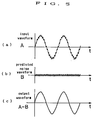
- Cancel means 7 subtracts the noise predicted by the noise prediction means 6 from the Fourier-transformed signal with a mingling of noise.
- the cancellation with the time as a basis is performed in a manner to subtract the predicted noise waveform (b) from the noise-contained voice signal (a) as shown in Fig. 5, thereby allowing only the signal to be taken out (c).
- the cancellation with the frequency as a basis is performed in such a manner that the noise-contained voice signal (a) is Fourier transformed (b), then from the signal thus transformed ,the predicted noise spectrum (c) is subtracted (d) , and the remain is inverse Fourier transformed to obtain a voice signal without noise (e).
- the portion without signal can be determined to be only noise, so that a signal obtained by inversing the output of the FFT means 3 is generated, and in the portion without signal, the inversed signal is added directly to the output of the FFT means 3 to eliminate completely noise.
- IFFT means 8 as an example of signal composition means, inverse-Fourier transforms the noise-eliminated signal obtained by the cancel means 7.
- D/A conversion means 9 converts the noise-eliminated voice signal being a digital signal obtained by the IFFT means 8 to an analog signal.
- the f in FIG.2 indicates the noise-eliminated signal being the analog signal.
- a voice recognizer 10 recognizes what word the noise-eliminated voice signal thus obtained is.
- the microphone 1 inputs therein a voice with a mingling of noise and outputs the voice signal with a mingling of noise (S + N) (see Fig.2, a ).
- the A/D conversion means 2 converts the voice signal with a mingling of noise being an analog signal to a digital signal.
- the FFT means 3 performs fast Fourier transfor-mation on the voice signal with a mingling of noise thus converted to the digital signal (see Fig.2, b ).
- the signal detection means 45 detects a signal portion from the signal with a mingling of noise thus Fourier transformed.
- the cepstrum analysis means 4 performs cepstrum analysis on the Fourier-transformed signal.
- the signal detection means 5 detects the signal portion utilizing the cepstrum thus analyzed (see Fig.2, c ).
- the means 5 detects the peak of the cepstrum to detect signal .
- the noise prediction means 6 inputs therein the Fourier-transformed signal with a mingling of noise, takes the data of p1 and p2 through pi at a frequency f1, and calculates the mean value of the noise portions p1 through pi to be made pj. Also, in the present embodiment, the noise prediction means 6 predicts the noise in the signal portion (see Fig.2, d ) , on the basis of the data of the noise portion at the nearest past when viewed from the point beginning with the signal portion when the signal is detected utilizing the signal portion information detected by the signal detection means 45 .
- the cancel means 7 subtracts the noise predicted by the noise prediction means 6 from the Fourier-transformed signal with a mingling of noise (see Fig.2, e ).
- the IFFT means 8 inverse-Fourier transforms the noise-eliminated signal obtained by the cancel means 7.
- the D/A conversion means 9 converts the noise-eliminated voice signal being a digital signal obtained by the IFFT means 8 to an analog signal (see Fig.2, f ).
- the voice recognizer 10 recognizes what word the noise-eliminated voice signal thus obtained is. Since the signal contains no noise, the recognition rate thereof becomes high.
- the noise detection means 6 of the present invention may be such means as to predict the noise component of the signal portion simply on the basis of the past noise information without utilizing the detected signal from the signal detection means 45. For example, the means 6 predicts simply that the past noise continues even in the signal portion.
- the present invention also can apply to the processing of other signals with a mingling of noise not limiting to that of voice signal.
- the present invention though implemented in software utilizing a computer, may also be implemented utilizing a dedicated hardware circuit.
- the signal processing device detects a signal portion from a frequency-analyzed signal with a mingling of noise, predicts a noise of the signal portion on the basis of the past noise information, and subtracts the predicted noise from the signal with a mingling of noise, thereby allowing a completely noise-eliminated signal to be generated.
- noise prediction means 6 uses a signal detected by signal detection means 45 as a trigger to predict a noise of the signal portion, the noise can more accurately predicted, whereby a signal from which the noise is more securely eliminated can be generated.
- Fig. 7 is a block diagram of a signal processing device in another embodiment of the preset invention.
- the numeral 71 indicates band division means for dividing a voice signal containing noise for each frequency band as an example of frequency analysis means for frequency analyzing a signal
- the numeral 72 does noise prediction means for inputting therein the output of the band division means 71 to predict a noise component
- the numeral 73 does cancel means for eliminating the noise in a such a manner as described later
- the numeral 74 does band composition means for composing a voice as an example of signal composition means for composing a signal.
- the band division means 71 is supplied with a voice containing noise/noise input, performs band division into m-channel frequency bands, and supplies them to the noise prediction means 72 and the cancel means 73.
- the noise prediction means 72 predicts noise component for each channel on the basis of the voice/noise input divided into m-channels, and supplies them to the cancel means 73. For example, the noise prediction is performed as described previously and as shown in Fig. 4.
- the cancel means 73 is supplied with a m-channel signal from the band division means 71 and the noise prediction means 72, cancels noise in a manner to subtract the noise for each channel in response to the cancel coefficient input, and supplies them to the band composition means 74.
- the cancellation is performed by multiplying the predicted noise component by the cancel coefficient.
- the cancellation with the time axis as an example of cancel method is performed as described previously and as shown in Fig. 5.
- the cancellation with the frequency as a basis is performed.
- the band composition means 74 composes the m-channel signal supplied from the cancel means 73 to obtain a voice output.
- a voice containing noise/noise input is band divided into m-channel signals by the band division means 71, and a noise component thereof is predicted for each channel by the noise prediction means 72.
- the noise component supplied for each channel from the noise prediction means 72 is eliminated.
- the noise elimination ratio at that time is properly set so as to improve articulation for each channel by the cancel coefficient input. For example, articulation is improved in such a manner that, where a voice signal exists, the cancel coefficient is made low even if a noise exists so as not to eliminate much the noise.
- the noise-eliminated m-channel signal obtained by the cancel means 73 is composed by the band composition means 73 to obtain a voice output.
- the noise elimination ratio of the cancel means 73 can be properly set for each band by the cancel coefficient input, and the cancel coefficient is accurately selected according to a voice, thereby allowing an articulation noise-suppressed voice output to be obtained.
- Fig. 8 is a block diagram of a signal processing device in an embodiment of another present invention.
- the same numeral is assigned to the same means as that of the embodiment in Fig. 7. That is, the numeral 71 indicates band division means, the numeral 72 does noise prediction means, the numeral 73 does cancel means, and the numeral 74 does band composition means.
- Pitch frequency detection means 87 detects a pitch frequency of the voice of the inputted voice/noise input and supplies it to channel coefficient setting means 88. The pitch frequency of the voice is determined by various method as shown in Table 1 and expresses the presence/absence and characteristic of a voice.
- the cancel coefficient setting means 88 is configured in a manner to set a number m of cancel coefficients on the basis of the pitch frequency supplied from the pitch frequency detection means 87 and supply them to the cancel means 73.
- a voice containing noise/noise input is band-divided into m-channel signals by the band division means 71, and a noise component thereof is predicted for each channel by the noise prediction means 72.
- the noise component supplied for each channel from the noise Table 1 Classification Pitch extraction method.
- I Waveform Processing (1)Parallel Processing Performs decision by majority of pitch periods extracted by 6-class simple waveform peak detector. (2)Data Reduction Casts away data other than pitch pulse candidates from waveform data by various logic operations. (3)Zero Crossing Count Aims at repeated pattern with respect to number of zero crosses of waveform.
- (8)Period Histogram Determines histogram of higher harmonic of basic frequency on spectrum, and decides pitch by common divisor of higher harmonics. prediction means 72 is eliminated.
- the noise elimination ratio at that time is set for each channel by the cancel coefficient supplied from the cancel coefficient setting means 88. That is, when the predicted noise component represents a i , signal containing noise b i and cancel coefficient alpha i , the output c i of the cancel means 73 becomes ( b i - alpha ⁇ i x a i ).
- the cancel coefficient thereof is determined on the basis of the information from the pitch frequency detection means 87. That is, the pitch frequency detection means 87 inputs therein a voice/noise input and detects the pitch frequency of the voice.
- the cancel coefficient setting means 88 sets cancel coefficients as shown in Fig.9 . That is, Fig. 9(a) shows cancel coefficients at each band, where the f0-f3 indicates the entire band of the voice/noise input. The f0-f3 is divided into m-channels to set the cancel coefficient. The f1-f2 indicates particularly a band containing voice obtained utilizing pitch frequency. Thus, in the voice band, the cancel coefficient is made low (close to zero) to eliminate noise as little as possible, thereby causing articulation to be improved. That is because human acoustic sense can hear a voice even though the voice has a little noise. In the non-voice bands f0-f1 and f2-f3, the cancel coefficient is made 1 to remove sufficiently noise.
- the cancel coefficient in Fig.9(b) is used when it is firmly found that no voice exists and only noise is considered to exist, and is made 1 to remove sufficiently noise. For example, where no vowel continues to exist from view of peak frequency, the signal cannot be determined to be voice signal, so that the signal is determined to be noise. It is preferable that the cancel coefficient in Fig.9 (a) and (b) can be properly changed over.
- the present invention can apply not only to voice signal but also to other signals processing.
- the present invention though implemented in software utilizing a computer, may also be implemented utilizing a dedicated hardware circuit.
- the signal processing device comprises noise prediction means for predicting a noise component, cancel means into which a noise-predicted output of the noise prediction means, a frequency analysis output of frequency analysis means and a cancel coefficient signal are inputted and which cancels the noise component considering the cancel ratio from the frequency analysis output, and signal composition means for composing the canceled output of the cancel means, so that, when the noise component is eliminated from a voice containing a noise, the degree of the elimination is properly controlled, thereby allowing the noise to be eliminated and articulation to be improved.
- Fig. 10 is a block diagram of a signal processing device in an embodiment of the present invention.
- the device is configured as shown in Fig. 10. That is, a noise prediction section 101 predicts a noise by a voice/noise input and by a control signal supplied by a voice detection section 103, and supplies a predicted noise to a cancel section 102.
- the cancel section 102 eliminates the noise from the voice/noise input in response to the predicted noise supplied from the noise prediction section 101 to obtain a voice output, and supplies the voice output to the voice detection section 103.
- the voice detection section 103 detects the presence/absence of actual voice by the voice output to obtain a voice-detected output, and supplies the voice-detected output as a control signal to the noise prediction section 101.
- a voice overlapping with noise/noise input is supplied to the cancel section 102 where the noise is eliminated in response to the predicted noise supplied from the noise prediction section 101 to obtain a voice output.
- the voice/noise input from which the noise is eliminated by the cancel section 102 is supplied to the voice detection section 103 where the presence/ absence of voice is detected to obtain a voice-detected output.
- the noise prediction section 101 operates such that the section uses as a control signal the voice-detected output indicating the presence/absence of a voice supplied from the voice detection section 103 to predict the noise of the voice/noise input signal, and supplies the voice-detected signal to the cancel section 102.
- voice detection is performed by the signal in which a noise is previously eliminated from a voice/noise input, thereby allowing the presence/absence of a voice to be accurately detected regardless of noise.
- noise prediction can also be performed accurately and the noise is eliminated effectively from the voice/noise input to obtain a clear voice output.
- Fig. 11 is a block diagram of a signal processing device in an embodiment of the present invention.
- the device is configured as shown in Fig. 11. That is, a first cancel section 105 eliminates a noise predicted by a first noise prediction section 104 from a voice/noise input, and supplies the noise-eliminated signal to a voice detection section 106, a second noise prediction section 107 and a second cancel section 108.
- the voice detection section 106 detects the presence/absence of the signal supplied from the first cancel section 105 to obtain a voice-detected output, and supplies the voice-detected output as a control signal to the first noise prediction section 104 and the second noise prediction section 107.
- the second cancel section 108 eliminates the noise predicted by the second noise prediction section 107 from the signal supplied from the first cancel section 105 to obtain a voice output.
- the first noise prediction section 104 and the second noise prediction section 107 both use the control signal from the voice detection section 106 to predict the noise of the voice/noise input and to predict the noise of the signal supplied from the first cancel section 105, respectively. Then, the second noise prediction section 107 supplies the predicted-result to the second cancel section 108 which in turn makes the canceled-result a voice output.
- a voice overlapping with noise/noise input is supplied to the first cancel section 105 where the noise is eliminated in response to a predicted noise supplied from the first noise prediction section 104.
- a first voice output from which the noise has been previously eliminated by the first cancel section 105 is supplied to the second cancel section 108 where the noise is further eliminated accurately in response to a second predicted noise supplied from the second, noise prediction section 107 to obtain a voice output.
- the first voice output from which the noise has been previously eliminated by the first cancel section 105 is supplied to the voice detection section 106 where the presence/absence is detected to obtain a voice-detected output (control signal).
- the first noise prediction section 104 uses the control signal indicating the presence/absence of a voice supplied from the voice detection section 106 to predict the noise of the voice/noise input, and supplies a first noise-predicted signal to the first cancel section 105.
- the second noise prediction section 107 operates such that the section 107 uses similarly the control signal indicating the presence/ absence of a voice supplied from the voice detection section 106 to further predict accurately the noise from the first voice output signal from which the noise has been previously eliminated by the first cancel section 105, and supplies the second predicted noise to the second cancel section 108.
- the presence/absence of a voice can be accurately detected regardless of noise, and the noise is further predicted accurately and eliminated from the first voice output from which the noise has been previously eliminated, thereby allowing a much lower level and rapidly fluctuated unsteady noise to be eliminated.
- Fig. 12 is a block diagram of a signal processing device in an embodiment of another present invention.
- the device is configured as shown in Fig. 12. That is, an FET processing section 121 transforms an input signal to a frequency-region signal, and supplies the transformed signal to a cepstrum peak detection section 122, a noise prediction section 125 and a cancel section 126.
- the cepstrum peak detection section 122 detects the cepstrum peak from the frequency-region signal obtained from the FET processing section 121, and supplies the detected cepstrum peak to a pitch frequency estimation section 123.
- the pitch frequency estimate section 123 estimates a pitch frequency from the cepstrum peak and supplies the pitch frequency to an window generation section 124 which in turn generates a window in response to the pitch frequency and supplies the window to a pitch frequency emphasis section 127.
- the noise prediction section 125 performs noise prediction for the signal supplied from the FET processing section 121 and supplies the noise-predicted signal to the cancel section 126 which in turn processes the signal supplied from the FET processing section 121 according to the predicted noise, and supplies the processed signal to the pitch frequency emphasis section 127.
- the pitch frequency emphasis section 127 performs pitch-frequency-emphasis-processing by the signals supplied from the window generation section 124 and the cancel section 126, and supplies the processed result to an IFFT section 128 which in turn transforms the signal to a time-region signal for output.
- an input signal to the present device is transformed to a frequency-region signal by the FET processing section 121.
- the input signal transformed to frequency region is detected for the cepstrum peak thereof by the cepstrum peak detection section 122, and further determined for the pitch frequency thereof by the pitch frequency estimate section 123.
- the window generation section 124 generates a proper window to perform voice emphasis as the frequency-region data, and supplies the window to the pitch frequency emphasis section 127.
- the noise prediction section 125 performs noise prediction for the input signal transformed to frequency region, determines the noise component in the frequency region, and supplies the noise component to the cancel section 126.
- the cancel section 126 eliminates accurately for each frequency component the noise component in the frequency region obtained by the noise prediction section 125 , from the input signal transformed to the frequency-region signal supplied from the FET processing section 121, and supplies the noise-eliminated signal to the pitch frequency emphasis section 127.
- the pitch frequency emphasis section 127 controls the noise-eliminated frequency signal obtained from the cancel section 126 in response to the window to perform voice emphasis obtained from the window generation section 124, performs voice emphasis, and supplies the voice-emphasized signal to the IFFT processing section 128.
- the IFFT processing section 128 transforms the signal from the pitch frequency emphasis section 127 to a time-region signal for output.
- a noise is eliminated from the signal in which a voice overlaps the noise, and the pitch frequency emphasis section is provided to emphasize the voice component, thereby allowing a voice signal with an excellent articulation to be obtained.
- the window generated by the window generation section 124 in the above embodiment represents a voice harmonic wave structure
- the window may be a comb filter and a low-pass filter.
- the pitch frequency emphasis section 127 can be simply implemented in a multiplication circuit.
- a device which eliminates a noise by transforming a signal to frequency-region comprises pitch frequency prediction means for predicting a pitch frequency, window generation means for generating a window in response to the pitch frequency, noise prediction means, cancel means for eliminating the noise in response to the output of the noise prediction means, and pitch frequency emphasis means for emphasizing the pitch of the canceled-output of the cancel means using the window of the window generation means, whereby the noise can be eliminated from the signal in which a voice overlaps the noise and further the voice component be emphasized to obtain a voice signal with a high articulation.
Applications Claiming Priority (13)
| Application Number | Priority Date | Filing Date | Title |
|---|---|---|---|
| JP2008593A JPH03212697A (ja) | 1990-01-18 | 1990-01-18 | 信号処理装置 |
| JP859390 | 1990-01-18 | ||
| JP2008594A JP2830276B2 (ja) | 1990-01-18 | 1990-01-18 | 信号処理装置 |
| JP859490 | 1990-01-18 | ||
| JP8594/90 | 1990-01-18 | ||
| JP8593/90 | 1990-01-18 | ||
| JP3320990 | 1990-02-13 | ||
| JP33209/90 | 1990-02-13 | ||
| JP33212/90 | 1990-02-13 | ||
| JP3321290 | 1990-02-13 | ||
| JP3321290 | 1990-02-13 | ||
| JP2033209A JP2836889B2 (ja) | 1990-02-13 | 1990-02-13 | 信号処理装置 |
| EP91100591A EP0438174B1 (fr) | 1990-01-18 | 1991-01-18 | Dispositif de traitement d'un signal |
Related Parent Applications (2)
| Application Number | Title | Priority Date | Filing Date |
|---|---|---|---|
| EP91100591A Division EP0438174B1 (fr) | 1990-01-18 | 1991-01-18 | Dispositif de traitement d'un signal |
| EP91100591A Division-Into EP0438174B1 (fr) | 1990-01-18 | 1991-01-18 | Dispositif de traitement d'un signal |
Publications (3)
| Publication Number | Publication Date |
|---|---|
| EP0637012A2 true EP0637012A2 (fr) | 1995-02-01 |
| EP0637012A3 EP0637012A3 (en) | 1995-03-01 |
| EP0637012B1 EP0637012B1 (fr) | 1999-12-29 |
Family
ID=27454980
Family Applications (2)
| Application Number | Title | Priority Date | Filing Date |
|---|---|---|---|
| EP94108160A Expired - Lifetime EP0637012B1 (fr) | 1990-01-18 | 1991-01-18 | Appareil de réduction de bruit |
| EP91100591A Expired - Lifetime EP0438174B1 (fr) | 1990-01-18 | 1991-01-18 | Dispositif de traitement d'un signal |
Family Applications After (1)
| Application Number | Title | Priority Date | Filing Date |
|---|---|---|---|
| EP91100591A Expired - Lifetime EP0438174B1 (fr) | 1990-01-18 | 1991-01-18 | Dispositif de traitement d'un signal |
Country Status (9)
| Country | Link |
|---|---|
| US (1) | US6038532A (fr) |
| EP (2) | EP0637012B1 (fr) |
| KR (1) | KR950011964B1 (fr) |
| AU (1) | AU633673B2 (fr) |
| CA (1) | CA2034354C (fr) |
| DE (2) | DE69131883T2 (fr) |
| FI (1) | FI104663B (fr) |
| HK (2) | HK184895A (fr) |
| NO (1) | NO306800B1 (fr) |
Cited By (8)
| Publication number | Priority date | Publication date | Assignee | Title |
|---|---|---|---|---|
| WO1998039768A1 (fr) * | 1997-03-03 | 1998-09-11 | Telefonaktiebolaget Lm Ericsson (Publ) | Procede de post-traitement a haute resolution pour decodeur vocal |
| WO1998047315A1 (fr) * | 1997-04-16 | 1998-10-22 | Dspfactory Ltd. | Procede et dispositif servant a limiter le bruit, en particulier, pour des protheses auditives |
| EP0969692A1 (fr) * | 1997-03-06 | 2000-01-05 | Asahi Kasei Kogyo Kabushiki Kaisha | Procede et dispositif de traitement de la parole |
| US6032114A (en) * | 1995-02-17 | 2000-02-29 | Sony Corporation | Method and apparatus for noise reduction by filtering based on a maximum signal-to-noise ratio and an estimated noise level |
| EP1081685A2 (fr) * | 1999-09-01 | 2001-03-07 | TRW Inc. | Procédé de réduction de bruit dans un signal de parole utilisant un microphone unique |
| DE10144076A1 (de) * | 2001-09-07 | 2003-03-27 | Daimler Chrysler Ag | Vorrichtung und Verfahren zur Früherkennung und Vorhersage von Aggregateschädigungen |
| US7593847B2 (en) * | 2003-10-25 | 2009-09-22 | Samsung Electronics Co., Ltd. | Pitch detection method and apparatus |
| EP3242295A1 (fr) * | 2016-05-06 | 2017-11-08 | Nxp B.V. | Un appareil de traitement de signal |
Families Citing this family (37)
| Publication number | Priority date | Publication date | Assignee | Title |
|---|---|---|---|---|
| EP0763812B1 (fr) * | 1990-05-28 | 2001-06-20 | Matsushita Electric Industrial Co., Ltd. | Dispositif de traitement d'un signal de parole pour la détection d'un signal de parole dans un signal de parole contenant du bruit |
| CA2125220C (fr) * | 1993-06-08 | 2000-08-15 | Joji Kane | Eliminateur de bruit pouvant empecher la degradation des signaux haute frequence apres l'elimination du bruit et des signaux d'un systeme emetteur de signaux symetriques |
| JP2739811B2 (ja) * | 1993-11-29 | 1998-04-15 | 日本電気株式会社 | 雑音抑圧方式 |
| FR2726392B1 (fr) * | 1994-10-28 | 1997-01-10 | Alcatel Mobile Comm France | Procede et dispositif de suppression de bruit dans un signal de parole, et systeme avec annulation d'echo correspondant |
| JP3591068B2 (ja) * | 1995-06-30 | 2004-11-17 | ソニー株式会社 | 音声信号の雑音低減方法 |
| FR2768546B1 (fr) * | 1997-09-18 | 2000-07-21 | Matra Communication | Procede de debruitage d'un signal de parole numerique |
| FR2768545B1 (fr) | 1997-09-18 | 2000-07-13 | Matra Communication | Procede de conditionnement d'un signal de parole numerique |
| FR2768544B1 (fr) | 1997-09-18 | 1999-11-19 | Matra Communication | Procede de detection d'activite vocale |
| FR2768547B1 (fr) | 1997-09-18 | 1999-11-19 | Matra Communication | Procede de debruitage d'un signal de parole numerique |
| US6269093B1 (en) | 1997-12-16 | 2001-07-31 | Nokia Mobile Phones Limited | Adaptive removal of disturbance in TDMA acoustic peripheral devices |
| US6480823B1 (en) * | 1998-03-24 | 2002-11-12 | Matsushita Electric Industrial Co., Ltd. | Speech detection for noisy conditions |
| DE19925046A1 (de) * | 1999-06-01 | 2001-05-03 | Alcatel Sa | Verfahren und Vorrichtung zur Unterdrückung von Rauschen und Echos |
| US7058572B1 (en) * | 2000-01-28 | 2006-06-06 | Nortel Networks Limited | Reducing acoustic noise in wireless and landline based telephony |
| DE10017646A1 (de) * | 2000-04-08 | 2001-10-11 | Alcatel Sa | Geräuschunterdrückung im Zeitbereich |
| US7139711B2 (en) * | 2000-11-22 | 2006-11-21 | Defense Group Inc. | Noise filtering utilizing non-Gaussian signal statistics |
| JP3574123B2 (ja) * | 2001-03-28 | 2004-10-06 | 三菱電機株式会社 | 雑音抑圧装置 |
| DE10126168A1 (de) * | 2001-05-30 | 2002-12-05 | Kostal Leopold Gmbh & Co Kg | Verfahren zum Bestimmen der Frequenz der im Ankerstromsignal eines kommutierten Gleichstrommotors enthaltenen Stromrippel |
| JP2003295899A (ja) * | 2002-03-28 | 2003-10-15 | Fujitsu Ltd | 音声入力装置 |
| JP2004297273A (ja) * | 2003-03-26 | 2004-10-21 | Kenwood Corp | 音声信号雑音除去装置、音声信号雑音除去方法及びプログラム |
| CA2454296A1 (fr) * | 2003-12-29 | 2005-06-29 | Nokia Corporation | Methode et dispositif d'amelioration de la qualite de la parole en presence de bruit de fond |
| US7692683B2 (en) * | 2004-10-15 | 2010-04-06 | Lifesize Communications, Inc. | Video conferencing system transcoder |
| US20060248210A1 (en) * | 2005-05-02 | 2006-11-02 | Lifesize Communications, Inc. | Controlling video display mode in a video conferencing system |
| JP4171922B2 (ja) * | 2006-04-12 | 2008-10-29 | 船井電機株式会社 | ミュート装置、液晶ディスプレイテレビ、及びミュート方法 |
| US8140325B2 (en) * | 2007-01-04 | 2012-03-20 | International Business Machines Corporation | Systems and methods for intelligent control of microphones for speech recognition applications |
| US20080312916A1 (en) * | 2007-06-15 | 2008-12-18 | Mr. Alon Konchitsky | Receiver Intelligibility Enhancement System |
| US8319814B2 (en) * | 2007-06-22 | 2012-11-27 | Lifesize Communications, Inc. | Video conferencing system which allows endpoints to perform continuous presence layout selection |
| US8139100B2 (en) * | 2007-07-13 | 2012-03-20 | Lifesize Communications, Inc. | Virtual multiway scaler compensation |
| US8514265B2 (en) * | 2008-10-02 | 2013-08-20 | Lifesize Communications, Inc. | Systems and methods for selecting videoconferencing endpoints for display in a composite video image |
| US20100110160A1 (en) * | 2008-10-30 | 2010-05-06 | Brandt Matthew K | Videoconferencing Community with Live Images |
| US8643695B2 (en) * | 2009-03-04 | 2014-02-04 | Lifesize Communications, Inc. | Videoconferencing endpoint extension |
| US8456510B2 (en) * | 2009-03-04 | 2013-06-04 | Lifesize Communications, Inc. | Virtual distributed multipoint control unit |
| US8350891B2 (en) * | 2009-11-16 | 2013-01-08 | Lifesize Communications, Inc. | Determining a videoconference layout based on numbers of participants |
| JP5589631B2 (ja) | 2010-07-15 | 2014-09-17 | 富士通株式会社 | 音声処理装置、音声処理方法および電話装置 |
| EP2619753B1 (fr) * | 2010-12-24 | 2014-05-21 | Huawei Technologies Co., Ltd. | Procédé et appareil destinés à une détection adaptative de l'activité vocale dans un signal audio d'entrée |
| JP5862349B2 (ja) * | 2012-02-16 | 2016-02-16 | 株式会社Jvcケンウッド | ノイズ低減装置、音声入力装置、無線通信装置、およびノイズ低減方法 |
| US9280984B2 (en) | 2012-05-14 | 2016-03-08 | Htc Corporation | Noise cancellation method |
| KR101428245B1 (ko) * | 2012-12-05 | 2014-08-07 | 현대자동차주식회사 | 음성 인식 장치 및 방법 |
Family Cites Families (8)
| Publication number | Priority date | Publication date | Assignee | Title |
|---|---|---|---|---|
| US4301329A (en) * | 1978-01-09 | 1981-11-17 | Nippon Electric Co., Ltd. | Speech analysis and synthesis apparatus |
| US4344150A (en) * | 1980-07-10 | 1982-08-10 | Newmont Mining Corporation | Coherent noise cancelling filter |
| US4454609A (en) * | 1981-10-05 | 1984-06-12 | Signatron, Inc. | Speech intelligibility enhancement |
| WO1985001586A1 (fr) * | 1983-09-26 | 1985-04-11 | Exploration Logging, Inc. | Filtre d'amortissement du bruit |
| US4630305A (en) * | 1985-07-01 | 1986-12-16 | Motorola, Inc. | Automatic gain selector for a noise suppression system |
| US4811404A (en) * | 1987-10-01 | 1989-03-07 | Motorola, Inc. | Noise suppression system |
| IL84948A0 (en) * | 1987-12-25 | 1988-06-30 | D S P Group Israel Ltd | Noise reduction system |
| US4912767A (en) * | 1988-03-14 | 1990-03-27 | International Business Machines Corporation | Distributed noise cancellation system |
-
1991
- 1991-01-07 AU AU68687/91A patent/AU633673B2/en not_active Ceased
- 1991-01-16 KR KR1019910000600A patent/KR950011964B1/ko not_active IP Right Cessation
- 1991-01-17 CA CA002034354A patent/CA2034354C/fr not_active Expired - Fee Related
- 1991-01-18 FI FI910292A patent/FI104663B/fi active
- 1991-01-18 NO NO910220A patent/NO306800B1/no unknown
- 1991-01-18 EP EP94108160A patent/EP0637012B1/fr not_active Expired - Lifetime
- 1991-01-18 DE DE69131883T patent/DE69131883T2/de not_active Expired - Fee Related
- 1991-01-18 DE DE69105760T patent/DE69105760T2/de not_active Expired - Fee Related
- 1991-01-18 EP EP91100591A patent/EP0438174B1/fr not_active Expired - Lifetime
-
1993
- 1993-07-23 US US08/095,179 patent/US6038532A/en not_active Expired - Fee Related
-
1995
- 1995-12-07 HK HK184895A patent/HK184895A/xx not_active IP Right Cessation
-
1998
- 1998-09-10 HK HK98110578A patent/HK1010009A1/xx not_active IP Right Cessation
Non-Patent Citations (4)
| Title |
|---|
| ELECTRONICS & COMMUNICATIONS IN JAPAN, vol.64, no.9, September 1981, MARYLAND, USA pages 21 - 30 H.NAGABUCHI ET AL. 'Quality improvement of synthesised speech in noisy speech analysis-synthesis processing' * |
| ICASSP 87, 6 April 1987, DALLAS pages 181 - 184 D.G.CHILDERS ET AL. 'Co-channel speech separation' * |
| ICASSP 89, vol.1, 23 May 1989, GLASGOW pages 211 - 214 W.M. KUSHNER ET AL. 'The effects of subtractive-type speech enhancement/noise reduction algorithms on parameter estimation for improved recognition and coding in high noise environments' * |
| IEEE COM. MAGAZINE, vol.27, no.2, February 1989, NEW YORK pages 46 - 52 D. O'SHAUGHNESSY 'Enhancing speech degraded by additive noise or interfering speakers' * |
Cited By (17)
| Publication number | Priority date | Publication date | Assignee | Title |
|---|---|---|---|---|
| US6032114A (en) * | 1995-02-17 | 2000-02-29 | Sony Corporation | Method and apparatus for noise reduction by filtering based on a maximum signal-to-noise ratio and an estimated noise level |
| WO1998039768A1 (fr) * | 1997-03-03 | 1998-09-11 | Telefonaktiebolaget Lm Ericsson (Publ) | Procede de post-traitement a haute resolution pour decodeur vocal |
| US6138093A (en) * | 1997-03-03 | 2000-10-24 | Telefonaktiebolaget Lm Ericsson | High resolution post processing method for a speech decoder |
| US7440891B1 (en) | 1997-03-06 | 2008-10-21 | Asahi Kasei Kabushiki Kaisha | Speech processing method and apparatus for improving speech quality and speech recognition performance |
| EP0969692A1 (fr) * | 1997-03-06 | 2000-01-05 | Asahi Kasei Kogyo Kabushiki Kaisha | Procede et dispositif de traitement de la parole |
| EP0969692A4 (fr) * | 1997-03-06 | 2005-03-09 | Asahi Chemical Ind | Procede et dispositif de traitement de la parole |
| EP1326479A2 (fr) * | 1997-04-16 | 2003-07-09 | DSPFactory Ltd. | Procédé et dispositif servant à réduire le bruit, en particulier pour des prothèses auditives |
| EP1326479A3 (fr) * | 1997-04-16 | 2005-03-23 | DSPFactory Ltd. | Procédé et dispositif servant à réduire le bruit, en particulier pour des prothèses auditives |
| US7016507B1 (en) | 1997-04-16 | 2006-03-21 | Ami Semiconductor Inc. | Method and apparatus for noise reduction particularly in hearing aids |
| WO1998047315A1 (fr) * | 1997-04-16 | 1998-10-22 | Dspfactory Ltd. | Procede et dispositif servant a limiter le bruit, en particulier, pour des protheses auditives |
| EP1081685A3 (fr) * | 1999-09-01 | 2002-04-24 | TRW Inc. | Procédé de réduction de bruit dans un signal de parole utilisant un microphone unique |
| EP1081685A2 (fr) * | 1999-09-01 | 2001-03-07 | TRW Inc. | Procédé de réduction de bruit dans un signal de parole utilisant un microphone unique |
| DE10144076A1 (de) * | 2001-09-07 | 2003-03-27 | Daimler Chrysler Ag | Vorrichtung und Verfahren zur Früherkennung und Vorhersage von Aggregateschädigungen |
| US7039557B2 (en) | 2001-09-07 | 2006-05-02 | Daimlerchrysler Ag | Device and method for the early recognition and prediction of unit damage |
| US7593847B2 (en) * | 2003-10-25 | 2009-09-22 | Samsung Electronics Co., Ltd. | Pitch detection method and apparatus |
| EP3242295A1 (fr) * | 2016-05-06 | 2017-11-08 | Nxp B.V. | Un appareil de traitement de signal |
| US10297272B2 (en) | 2016-05-06 | 2019-05-21 | Nxp B.V. | Signal processor |
Also Published As
| Publication number | Publication date |
|---|---|
| EP0438174A3 (en) | 1991-09-11 |
| FI910292A (fi) | 1991-07-19 |
| NO910220D0 (no) | 1991-01-18 |
| AU6868791A (en) | 1991-07-25 |
| EP0637012B1 (fr) | 1999-12-29 |
| HK1010009A1 (en) | 1999-06-11 |
| DE69131883T2 (de) | 2000-08-10 |
| DE69105760D1 (de) | 1995-01-26 |
| KR910015109A (ko) | 1991-08-31 |
| NO306800B1 (no) | 1999-12-20 |
| CA2034354C (fr) | 1999-09-14 |
| EP0438174B1 (fr) | 1994-12-14 |
| AU633673B2 (en) | 1993-02-04 |
| US6038532A (en) | 2000-03-14 |
| FI910292A0 (fi) | 1991-01-18 |
| HK184895A (en) | 1995-12-15 |
| NO910220L (no) | 1991-07-19 |
| KR950011964B1 (ko) | 1995-10-12 |
| DE69105760T2 (de) | 1995-04-27 |
| FI104663B (fi) | 2000-04-14 |
| EP0438174A2 (fr) | 1991-07-24 |
| CA2034354A1 (fr) | 1991-07-19 |
| DE69131883D1 (de) | 2000-02-03 |
| EP0637012A3 (en) | 1995-03-01 |
Similar Documents
| Publication | Publication Date | Title |
|---|---|---|
| EP0637012B1 (fr) | Appareil de réduction de bruit | |
| EP0459382B1 (fr) | Dispositif de traitement d'un signal de parole pour la détection d'un signal de parole dans un signal de parole contenant du bruit | |
| US6108610A (en) | Method and system for updating noise estimates during pauses in an information signal | |
| US6377637B1 (en) | Sub-band exponential smoothing noise canceling system | |
| US6363345B1 (en) | System, method and apparatus for cancelling noise | |
| US5742927A (en) | Noise reduction apparatus using spectral subtraction or scaling and signal attenuation between formant regions | |
| EP0459362B1 (fr) | Processeur de signal de parole | |
| EP1326479B1 (fr) | Procédé et dispositif servant à réduire le bruit, en particulier pour des prothèses auditives | |
| EP0809842B1 (fr) | Filtre vocal adaptatif | |
| EP1520395B1 (fr) | Systeme d'optimisation audio en fonction de l'energie spectrale fixe | |
| US6073152A (en) | Method and apparatus for filtering signals using a gamma delay line based estimation of power spectrum | |
| US5204906A (en) | Voice signal processing device | |
| EP0459384B1 (fr) | Processeur de signal de parole pour decouper un signal de parole d'un signal de parole bruité | |
| JP2836271B2 (ja) | 雑音除去装置 | |
| SE513892C2 (sv) | Spektral effekttäthetsestimering av talsignal Metod och anordning med LPC-analys | |
| JP3693022B2 (ja) | 音声認識方法及び音声認識装置 | |
| JP2979714B2 (ja) | 音声信号処理装置 | |
| JPH03212698A (ja) | 信号処理装置 | |
| JP3410789B2 (ja) | 音声認識装置 | |
| JP3205141B2 (ja) | 音声分析方式 | |
| JPH03236000A (ja) | 音声信号処理装置 | |
| JPH03180900A (ja) | 音声認識装置の雑音除去システム | |
| JPH0844390A (ja) | 音声認識装置 |
Legal Events
| Date | Code | Title | Description |
|---|---|---|---|
| PUAI | Public reference made under article 153(3) epc to a published international application that has entered the european phase |
Free format text: ORIGINAL CODE: 0009012 |
|
| PUAL | Search report despatched |
Free format text: ORIGINAL CODE: 0009013 |
|
| AC | Divisional application: reference to earlier application |
Ref document number: 438174 Country of ref document: EP |
|
| AK | Designated contracting states |
Kind code of ref document: A2 Designated state(s): CH DE FR GB LI NL SE |
|
| AK | Designated contracting states |
Kind code of ref document: A3 Designated state(s): CH DE FR GB LI NL SE |
|
| 17P | Request for examination filed |
Effective date: 19950119 |
|
| GRAG | Despatch of communication of intention to grant |
Free format text: ORIGINAL CODE: EPIDOS AGRA |
|
| 17Q | First examination report despatched |
Effective date: 19990113 |
|
| GRAG | Despatch of communication of intention to grant |
Free format text: ORIGINAL CODE: EPIDOS AGRA |
|
| GRAH | Despatch of communication of intention to grant a patent |
Free format text: ORIGINAL CODE: EPIDOS IGRA |
|
| GRAH | Despatch of communication of intention to grant a patent |
Free format text: ORIGINAL CODE: EPIDOS IGRA |
|
| GRAA | (expected) grant |
Free format text: ORIGINAL CODE: 0009210 |
|
| AC | Divisional application: reference to earlier application |
Ref document number: 438174 Country of ref document: EP |
|
| AK | Designated contracting states |
Kind code of ref document: B1 Designated state(s): CH DE FR GB LI NL SE |
|
| REG | Reference to a national code |
Ref country code: CH Ref legal event code: EP |
|
| REF | Corresponds to: |
Ref document number: 69131883 Country of ref document: DE Date of ref document: 20000203 |
|
| REG | Reference to a national code |
Ref country code: CH Ref legal event code: NV Representative=s name: BUECHEL & PARTNER AG PATENTBUERO |
|
| ET | Fr: translation filed | ||
| PLBE | No opposition filed within time limit |
Free format text: ORIGINAL CODE: 0009261 |
|
| STAA | Information on the status of an ep patent application or granted ep patent |
Free format text: STATUS: NO OPPOSITION FILED WITHIN TIME LIMIT |
|
| 26N | No opposition filed | ||
| REG | Reference to a national code |
Ref country code: GB Ref legal event code: IF02 |
|
| PGFP | Annual fee paid to national office [announced via postgrant information from national office to epo] |
Ref country code: SE Payment date: 20070104 Year of fee payment: 17 |
|
| PGFP | Annual fee paid to national office [announced via postgrant information from national office to epo] |
Ref country code: DE Payment date: 20070111 Year of fee payment: 17 |
|
| PGFP | Annual fee paid to national office [announced via postgrant information from national office to epo] |
Ref country code: NL Payment date: 20070115 Year of fee payment: 17 Ref country code: CH Payment date: 20070115 Year of fee payment: 17 |
|
| PGFP | Annual fee paid to national office [announced via postgrant information from national office to epo] |
Ref country code: GB Payment date: 20070117 Year of fee payment: 17 |
|
| PGFP | Annual fee paid to national office [announced via postgrant information from national office to epo] |
Ref country code: FR Payment date: 20070109 Year of fee payment: 17 |
|
| REG | Reference to a national code |
Ref country code: CH Ref legal event code: PL |
|
| EUG | Se: european patent has lapsed | ||
| GBPC | Gb: european patent ceased through non-payment of renewal fee |
Effective date: 20080118 |
|
| NLV4 | Nl: lapsed or anulled due to non-payment of the annual fee |
Effective date: 20080801 |
|
| PG25 | Lapsed in a contracting state [announced via postgrant information from national office to epo] |
Ref country code: NL Free format text: LAPSE BECAUSE OF NON-PAYMENT OF DUE FEES Effective date: 20080801 Ref country code: LI Free format text: LAPSE BECAUSE OF NON-PAYMENT OF DUE FEES Effective date: 20080131 Ref country code: DE Free format text: LAPSE BECAUSE OF NON-PAYMENT OF DUE FEES Effective date: 20080801 Ref country code: CH Free format text: LAPSE BECAUSE OF NON-PAYMENT OF DUE FEES Effective date: 20080131 |
|
| REG | Reference to a national code |
Ref country code: FR Ref legal event code: ST Effective date: 20081029 |
|
| PG25 | Lapsed in a contracting state [announced via postgrant information from national office to epo] |
Ref country code: GB Free format text: LAPSE BECAUSE OF NON-PAYMENT OF DUE FEES Effective date: 20080118 |
|
| PG25 | Lapsed in a contracting state [announced via postgrant information from national office to epo] |
Ref country code: SE Free format text: LAPSE BECAUSE OF NON-PAYMENT OF DUE FEES Effective date: 20080119 |
|
| PG25 | Lapsed in a contracting state [announced via postgrant information from national office to epo] |
Ref country code: FR Free format text: LAPSE BECAUSE OF NON-PAYMENT OF DUE FEES Effective date: 20080131 |