EP0636956A2 - Aufdatverfahren - Google Patents
Aufdatverfahren Download PDFInfo
- Publication number
- EP0636956A2 EP0636956A2 EP94110920A EP94110920A EP0636956A2 EP 0636956 A2 EP0636956 A2 EP 0636956A2 EP 94110920 A EP94110920 A EP 94110920A EP 94110920 A EP94110920 A EP 94110920A EP 0636956 A2 EP0636956 A2 EP 0636956A2
- Authority
- EP
- European Patent Office
- Prior art keywords
- automation system
- updating
- update
- time
- address
- Prior art date
- Legal status (The legal status is an assumption and is not a legal conclusion. Google has not performed a legal analysis and makes no representation as to the accuracy of the status listed.)
- Granted
Links
Images

Classifications
-
- G—PHYSICS
- G06—COMPUTING; CALCULATING OR COUNTING
- G06F—ELECTRIC DIGITAL DATA PROCESSING
- G06F11/00—Error detection; Error correction; Monitoring
- G06F11/07—Responding to the occurrence of a fault, e.g. fault tolerance
- G06F11/16—Error detection or correction of the data by redundancy in hardware
- G06F11/20—Error detection or correction of the data by redundancy in hardware using active fault-masking, e.g. by switching out faulty elements or by switching in spare elements
- G06F11/2053—Error detection or correction of the data by redundancy in hardware using active fault-masking, e.g. by switching out faulty elements or by switching in spare elements where persistent mass storage functionality or persistent mass storage control functionality is redundant
- G06F11/2056—Error detection or correction of the data by redundancy in hardware using active fault-masking, e.g. by switching out faulty elements or by switching in spare elements where persistent mass storage functionality or persistent mass storage control functionality is redundant by mirroring
- G06F11/2082—Data synchronisation
-
- G—PHYSICS
- G05—CONTROLLING; REGULATING
- G05B—CONTROL OR REGULATING SYSTEMS IN GENERAL; FUNCTIONAL ELEMENTS OF SUCH SYSTEMS; MONITORING OR TESTING ARRANGEMENTS FOR SUCH SYSTEMS OR ELEMENTS
- G05B19/00—Programme-control systems
- G05B19/02—Programme-control systems electric
- G05B19/04—Programme control other than numerical control, i.e. in sequence controllers or logic controllers
- G05B19/042—Programme control other than numerical control, i.e. in sequence controllers or logic controllers using digital processors
- G05B19/0428—Safety, monitoring
-
- G—PHYSICS
- G06—COMPUTING; CALCULATING OR COUNTING
- G06F—ELECTRIC DIGITAL DATA PROCESSING
- G06F11/00—Error detection; Error correction; Monitoring
- G06F11/07—Responding to the occurrence of a fault, e.g. fault tolerance
- G06F11/16—Error detection or correction of the data by redundancy in hardware
- G06F11/1658—Data re-synchronization of a redundant component, or initial sync of replacement, additional or spare unit
-
- G—PHYSICS
- G06—COMPUTING; CALCULATING OR COUNTING
- G06F—ELECTRIC DIGITAL DATA PROCESSING
- G06F8/00—Arrangements for software engineering
- G06F8/60—Software deployment
- G06F8/65—Updates
- G06F8/656—Updates while running
-
- G—PHYSICS
- G05—CONTROLLING; REGULATING
- G05B—CONTROL OR REGULATING SYSTEMS IN GENERAL; FUNCTIONAL ELEMENTS OF SUCH SYSTEMS; MONITORING OR TESTING ARRANGEMENTS FOR SUCH SYSTEMS OR ELEMENTS
- G05B2219/00—Program-control systems
- G05B2219/20—Pc systems
- G05B2219/24—Pc safety
- G05B2219/24185—After repair, update redundant system during non critical periods
-
- G—PHYSICS
- G06—COMPUTING; CALCULATING OR COUNTING
- G06F—ELECTRIC DIGITAL DATA PROCESSING
- G06F11/00—Error detection; Error correction; Monitoring
- G06F11/07—Responding to the occurrence of a fault, e.g. fault tolerance
- G06F11/16—Error detection or correction of the data by redundancy in hardware
- G06F11/1629—Error detection by comparing the output of redundant processing systems
- G06F11/1633—Error detection by comparing the output of redundant processing systems using mutual exchange of the output between the redundant processing components
-
- G—PHYSICS
- G06—COMPUTING; CALCULATING OR COUNTING
- G06F—ELECTRIC DIGITAL DATA PROCESSING
- G06F11/00—Error detection; Error correction; Monitoring
- G06F11/07—Responding to the occurrence of a fault, e.g. fault tolerance
- G06F11/16—Error detection or correction of the data by redundancy in hardware
- G06F11/20—Error detection or correction of the data by redundancy in hardware using active fault-masking, e.g. by switching out faulty elements or by switching in spare elements
- G06F11/202—Error detection or correction of the data by redundancy in hardware using active fault-masking, e.g. by switching out faulty elements or by switching in spare elements where processing functionality is redundant
- G06F11/2038—Error detection or correction of the data by redundancy in hardware using active fault-masking, e.g. by switching out faulty elements or by switching in spare elements where processing functionality is redundant with a single idle spare processing component
Definitions
- the present invention relates to an update method for an additional automation system which is coupled to an automation system consisting of at least one initial automation system and controlling a technical process or a technical system by means of a processed program.
- Redundant automation systems are widely used.
- the automation systems are usually single or double redundant, i.e. two or three automation systems are used to control one and the same technical process or the same technical system.
- a subsystem fails and the technical system or the technical process is led through the remaining subsystem (initial automation system) or the remaining subsystems.
- this subsystem must be coupled to the at least one initial automation system. So far this has been done e.g. in that the initial automation system currently controlling the technical system interrupts the program processing, the necessary operating data are transferred from the start to the additional automation system and then the initial and additional automation systems continue the program processing and thus take over the management of the technical system together.
- the object of the present invention is therefore to provide an update method in which these disadvantages do not occur.
- the object is achieved in that the updating process is carried out without gushing.
- a technical system 1 - shown only schematically - in which a technical process takes place is controlled by the initial automation system 2.
- the automation system 2 is referred to below as the initial system.
- the automation system 2 ' is also referred to as an additional system.
- the starting system 2 has a processor 3 which, to control the technical system 1, processes a program which is stored in the working memory 4.
- the technical system 1 is controlled via the system interface 5.
- the additional system 2 ' essentially consists of the same components: processor 3', main memory 4 'and system interface 5'.
- the initial system 2 controls the technical system 1 exclusively and that the additional system 2 'is to be coupled to the initial system 2 in order to be able to take over the control of the technical system 1 immediately in the event of a failure of the initial system 2.
- the program in the working memory 4 'be identical to the program in the working memory 4 but the process data in the two automation systems 2, 2' must also match.
- the work memory 4 stores which update time is required in order to be able to update the additional system 2 ′.
- This update time is of course dependent on the scope of the data to be updated and the performance of the communication between the automation systems 2, 2 '.
- the initial system 2 is given the data configurations of non-time-critical states and the associated time periods during which the reaction to process changes is time-uncritical.
- the starting system 2 can compare the current process data with the data configurations of non-time-critical states and thus recognize non-time-critical states. If such a condition has been recognized, the associated time period during which the reaction to changes in state is not time-critical, compared with the update time. If the duration of the time-uncritical state exceeds the update time, the processor 3 activates the communication interface 7 via the control line 6, which then calls the data to be updated from the working memory 4 via the bus 8 and transmits it via the communication line 9 to the communication interface 7 ' Additional system 2 '. This in turn saves them in the working memory 4 'and signals the end of the update process to the processor 3'. From this moment on, both automation systems 2, 2 'are able to take over the control of the technical system immediately (so-called hot stand-by mode).
- a memory area of 100H is saved from the starting system 2 to the additional system 2 ', for example the memory area from 3400H to 3500H.
- the memory area from 3300H to 3400H if the address cycle falls
- 3500H to 3600H if the address cycle increases
- the additional system 2 ' may of course not execute the program or write peripheral accesses during the update. Only read peripheral access is permitted. It is even advantageous to carry out reading peripheral accesses, since this also automatically updates the additional system 2 '.
- the present invention provides two possible procedures. If the communication interfaces 7, 7 'and the communication line 9 are powerful, the following method is advantageously carried out: A transmission address is initially set equal to the start address, in this example 3000H. When the first time slice is reached, the first 100H bytes are transferred from the starting system 2 to the additional system 2 '.
- the transfer address is increased by the number of the transmitted data increased, in this case set to 3100H.
- all write accesses to the memory area from 3000H to 3100H that the starting system 2 executes are recorded. They are reported immediately via the communication interface 7 to the communication interface 7 ', which stores the addresses and the values of the newly written data in the additional memory 10'.
- the additional memory 10 ' is organized as a circulation buffer. The processor 3 'is therefore able to read the circulation buffer 10' again immediately and thus update the memory area of the main memory 4 'that has already been updated or keep it up to date.
- the next 100H bytes with the addresses from 3100H to 3200H are transferred - according to the example above.
- the transmission address is then set to 3200H.
- all write accesses to the memory area from 3000H to 3200H are immediately reported to the additional system 2 ', so that the memory area which has already been updated can in turn be kept updated.
- the updating is preferably carried out as follows: Analogous to the case described above, 100H bytes are transferred from the starting system 2 to the additional system 2 '. There they are first stored in the additional memory 10 '. During the program cycle between two time slices, the data written into the additional memory 10 'are compared with the corresponding data in the working memory 4' and then written into the working memory 4 '. The processor 3 'notes whether the data is the same. If the data is the same, the value of the counter 11 'is incremented by one. Otherwise the counter 11 'is set to the value zero.
- the update runs take place alternately with increasing and decreasing address runs.
- the updating is deemed to have been carried out if, during a predetermined number of successive time slices, equality has been found in all comparison processes, i.e. the transmitted data do not differ from the data already in the working memory 4.
- a test variable is determined for the data to be updated or the updated.
- the check variables can be, for example, a checksum or a signature.
- the test variables determined are exchanged via the communication interfaces 7, 7 'and compared with one another. Are the If the test parameters are the same, the update is considered finished. Otherwise, the counter 11 'is set to zero and a new update process is carried out.
Abstract
Description
- Die vorliegende Erfindung betrifft ein Aufdatverfahren für ein Zusatzautomatisierungssystem, das an ein aus mindestens einem Anfangsautomatisierungssystem bestehenden, mittels eines abgearbeiteten Programms einen technischen Prozeß bzw. eine technische Anlage steuernden Automatisierungssystem angekoppelt ist.
- Redundante Automatisierungssysteme sind weit verbreitet. Meist sind die Automatisierungssysteme dabei einfach oder doppelt redundant, d.h. es werden zwei bzw. drei Automatisierungssysteme zur Steuerung ein und desselben technischen Prozesses bzw. ein und derselben technischen Anlage verwendet. Bei einer derartigen Konfiguration kann es vorkommen, daß ein Teilsystem ausfällt und die technische Anlage bzw. der technische Prozeß durch das verbleibende Teilsystem (Anfangsautomatisierungssystem) bzw. die verbleibenden Teilsysteme geführt wird. Nach dem Austausch bzw. der Reparatur des ausgefallenen Teilsystems muß dieses Teilsystem wieder an das mindestens eine Anfangsautomatisierungssystem angekoppelt werden. Bisher geschieht dies z.B. dadurch, daß das die technische Anlage momentan steuernde Anfangsautomatisierungssystem die Programmabarbeitung unterbricht, die nötigen Betriebsdaten vom Anfangszum Zusatzautomatisierungssystem übertragen werden und sodann das Anfangs- und das Zusatzautomatisierungssystem die Programmabarbeitung fortsetzen und so gemeinsam die Führung der technischen Anlage übernehmen.
- Diese Vorgehensweise ist insofern nicht optimal, als während des Aufdatens eine Kontrolle der technischen Anlage nicht gewährleistet ist. Andererseits kann es unter Umständen schwierig, gefährlich und zeitaufwendig sein, eine Anlage herunterzufahren und später wieder zu starten.
- Die Aufgabe der vorliegenden Erfindung besteht folglich darin, ein Aufdatverfahren zur Verfügung zu stellen, bei dem diese Nachteile nicht auftreten.
- Die Aufgabe wird dadurch gelöst, daß das Aufdatverfahren aufdatstoßfrei abläuft.
- Dabei ist es beispielsweise möglich, daß zum Aufdaten ein zeitunkritischer Zustand des technischen Prozesses bzw. der technischen Anlage abgewartet wird, wobei dann das Aufdaten vollständig während dieses zeitunkritischen Zustands erfolgt.
- Ferner ist es möglich, daß das Aufdaten in Zeitscheiben erfolgt, die in die Programmabarbeitung des Anfangsautomatisierungssystems eingefügt werden.
- Weitere Vorteile und Einzelheiten ergeben sich aus der nachfolgenden Beschreibung eines Ausführungsbeispiels, anhand der Zeichnungen und in Verbindung mit den weiteren Unteransprüchen. Dabei zeigen:
- FIG 1 ein Blockschaltbild eines Automatisierungssystems;
- FIG 2 das Prinzip des Einstreuens der Zeitscheiben und
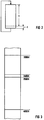
- FIG 3 einen Ausschnitt der Speicherbelegung der Teilsysteme.
- Gemäß FIG 1 wird eine - nur schematisch dargestellte - technische Anlage 1, in der ein technischer Prozeß abläuft, durch das Anfangsautomatisierungssystem 2 gesteuert. Das Automatisierungssystem 2 wird im folgenden kurz als Anfangssystem bezeichnet. Ebenso wird das Automatisierungssystem 2' als Zusatzsystem bezeichnet.
- Zur Steuerung der technischen Anlage 1 weist das Anfangssystem 2 einen Prozessor 3 auf, der zur Steuerung der technischen Anlage 1 ein Programm abarbeitet, das im Arbeitsspeicher 4 abgespeichert ist. Die Steuerung der technischen Anlage 1 erfolgt dabei über die Anlagenschnittstelle 5.
- Das Zusatzsystem 2' besteht im wesentlichen aus den gleichen Komponenten: Prozessor 3', Arbeitsspeicher 4' und Anlagenschnittstelle 5'.
- Im vorliegenden Fall ist angenommen, daß das Anfangssystem 2 die technische Anlage 1 ausschließlich steuert und daß das Zusatzsystem 2' an das Anfangssystem 2 angekoppelt werden soll, um bei einem Ausfall des Anfangssystems 2 die Steuerung der technischen Anlage 1 sofort übernehmen zu können. Hierzu muß nicht nur das Programm im Arbeitsspeicher 4' identisch mit dem Programm im Arbeitsspeicher 4 sein, sondern es müssen auch die Prozeßdaten in den beiden Automatisierungssystemen 2, 2' übereinstimmen.
- Um diese Übereinstimmung der Prozeßdaten aufdatstoßfrei zu erreichen, wird gemäß einer Ausführungsform der vorliegenden Erfindung im Arbeitsspeicher 4 abgelegt, welche Aufdatzeit benötigt wird, um das Aufdaten des Zusatzsystems 2' durchführen zu können. Diese Aufdatzeit ist selbstverständlich vom Umfang der aufzudatenden Daten und der Leistungsfähigkeit der Kommunikation zwischen den Automatisierungssystemen 2, 2' abhängig.
- Ferner sind dem Anfangssystem 2 die Datenkonfigurationen zeitunkritischer Zustände und die zugehörigen Zeitdauern, während derer das Reagieren auf Prozeßänderungen zeitunkritisch ist, vorgegeben. Dadurch kann das Anfangssystem 2 die momentanen Prozeßdaten mit den Datenkonfigurationen zeitunkritischer Zustände vergleichen und so zeitunkritische Zustände erkennen. Wenn ein derartiger Zustand erkannt worden ist, wird die zugehörige Zeitdauer, während derer die Reaktion auf Zustandsänderungen zeitunkritisch ist, mit der Aufdatzeit verglichen. Wenn die Dauer des zeitunkritischen Zustands die Aufdatzeit übersteigt, aktiviert der Prozessor 3 über die Steuerleitung 6 die Kommunikationsschnittstelle 7. Diese ruft dann über den Bus 8 die aufzudatenden Daten aus dem Arbeitsspeicher 4 ab und überträgt sie über die Kommunikationsleitung 9 an die Kommunikationsschnittstelle 7' des Zusatzsystems 2'. Dieses wiederum speichert sie im Arbeitsspeicher 4' ab und signalisiert das Beenden des Aufdatvorgangs dem Prozessor 3'. Von diesem Moment an sind beide Automatisierungssysteme 2, 2' in der Lage, sofort die Steuerung der technischen Anlage zu übernehmen (sogenannter hot stand by-Betrieb).
- Obenstehendes Verfahren ist optimal, wenn ein zeitunkritischer Zustand der technischen Anlage existiert, dessen Dauer die Aufdatzeit übersteigt. Wenn dagegen kein derartiger Zustand existiert, muß in Zeitscheiben aufgedatet werden, die zyklisch in die Programmbearbeitung eingefügt werden. Hierzu ist zu erwähnen, daß gemaß FIG 2 die Programmabarbeitung bei Automatisierungsgeräten in der Regel zyklisch erfolgt. Die Programmzykluszeit ist dabei in FIG 2 mit T bezeichnet. Am Ende eines Programmzyklus wird nun in kleinen Zeitscheiben, deren Dauer t beträgt, das Programmzusatzsystem 2' nach und nach aufgedatet. Die dadurch entstehende Verlängerung der Programmzykluszeit T ist dabei vernachlässigbar. Anstelle der Einfügung nur einer Zeitscheibe pro Zeitzyklus ist es selbstverständlich auch möglich, mehrere Zeitscheiben pro Programmzyklus einzufügen. Die Anzahl der Zeitscheiben ist dabei derart bemessen, daß sie mindestens einen vollständigen Aufdatdurchlauf entspricht.
- Gemäß FIG 3 umfassen die aufzudatenden Daten einen Speicherbereich mit der Anfangsadresse 3000H (H = hexadezimal) und der Endadresse 4000H. Während einer Zeitscheibe wird dabei jeweils ein Speicherbereich von 100H vom Anfangssystem 2 an das Zusatzsystem 2' übertragen, beispielsweise der Speicherbereich von 3400H bis 3500H. Bei der nächsten Zeitscheibe würde dann entweder der Speicherbereich von 3300H bis 3400H (bei fallendem Adreßdurchlauf) bzw. von 3500H bis 3600H übertragen werden (bei steigendem Adreßdurchlauf).
- Während jedes Programmzyklus werden mindestens einmal vom Anfangssystem 2 Eingangssignale von der technischen Anlage eingelesen und Ausgangssignale an die technische Anlage 1 ausgegeben. Das Zusatzsystem 2' dagegen darf wahrend des Aufdatens selbstverständlich weder das Programm noch schreibende Peripheriezugriffe ausführen. Nur lesende Peripheriezugriffe sind zugelassen. Das Mitausführen von lesenden Peripheriezugriffen ist sogar von Vorteil, da sich hierdurch das Zusatzsystem 2' zwangsweise mit aktualisiert.
- Wenn die Eingangssignale die einzigen Signale wären, deren Wert sich ändert, müßte der aufzudatende Speicherbereich nur einmal von Anfangssystem 2 an das Zusatzsystem 2' übertragen werden und ansonsten die Eingangssignale von der technischen Anlage 1 vom Zusatzsystem 2' mit eingelesen werden. Es ändern sich jedoch auch andere Signale, beispielsweise Zähler- und Timerwerte sowie die Ausgangssignale. Bevor der Aufdatvorgang als beendet angesehen wird, muß auch die Gleichheit dieser Daten sichergestellt sein. Hierzu werden durch die vorliegende Erfindung zwei mögliche Vorgehensweisen zur Verfügung gestellt. Wenn die Kommunikationsschnittstellen 7, 7' und die Kommunikationsleitung 9 leistungsfähig sind, wird mit Vorteil folgendes Verfahren ausgeführt:
Eine Übertragungsadresse wird zunächst gleich der Anfangsadresse gesetzt, im vorliegenden Beispiel also gleich 3000H. Bei Erreichen der ersten Zeitscheibe werden die ersten 100H Byte vom Anfangssystem 2 an das Zusatzsystem 2' übertragen. Sodann wird die Übertragungsadresse um die Anzahl der übertragenen Daten erhöht, im vorliegenden Fall also auf 3100H gesetzt. Während des nun folgenden Zyklus, also in der Zeit bis zum Erreichen der nächsten Zeitscheibe werden alle schreibenden Zugriffe auf den Speicherbereich von 3000H bis 3100H, die das Anfangssystem 2 ausführt, erfaßt. Sie werden über die Kommunikationsschnittstelle 7 sofort an die Kommunikationsschnittstelle 7' gemeldet, die die Adressen und die Werte der neu geschriebenen Daten im Zusatzspeicher 10' ablegt. Der Zusatzspeicher 10' ist in diesem Fall als Umlaufpuffer organisiert. Der Prozessor 3' ist daher in der Lage, den Umlaufpuffer 10' sofort wieder auszulesen und so den schon aufgedateten Speicherbereich des Arbeitsspeichers 4' zu aktualisieren bzw. auf dem aktuellen Stand zu halten. - Bei Erreichen der nächsten Zeitscheibe werden - gemäß obigem Beispiel - die nächsten 100H Byte mit den Adressen von 3100H bis 3200H übertragen. Die Übertragungsadresse wird sodann gleich 3200H gesetzt. Wahrend des nächsten Zyklus werden alle schreibenden Zugriffe auf den Speicherbereich von 3000H bis 3200H sofort an das Zusatzsystem 2' gemeldet, so daß wiederum der bereits aufgedatete Speicherbereich aktualisiert gehalten werden kann.
- Dieses Übertragen der Daten, Neusetzen der Übertragungsadresse und Aktualisieren des bereits aufgedatenen Speicherbereichs wird solange wiederholt, bis die Übertragungsadresse den Wert 4000H erreicht. Dann ist der Aufdatvorgang abgeschlossen und das Zusatzsystem 2' kann in den hot stand by-Betrieb übergehen.
- Wenn sich während des Aufdatens sehr viele Änderungen der bereits aufgedateten Datenbereiche ergeben, kann es geschehen, daß die Leistungsfähigkeit der Kommunikationseinrichtung zwischen den Automatisierungssystemen 2, 2' nicht ausreicht, um den bereits aufgedateten Speicherbereich aktualisiert zu halten. In diesem Fall muß das Anfangssystem 2 doch unterbrechen. Das Aufdaten kann in diesem Fall also doch nicht ganz aufdatstoßfrei erfolgen. In der bei weitem überwiegenden Mehrzahl der Fälle wird das Verfahren jedoch auch ohne Unterbrechung der Programmabarbeitung ausführbar sein.
- Wenn keine leistungsfähige Kommunikationseinrichtung zwischen den Automatisierungssystemen 2, 2' zur Verfügung steht, wird das Aufdaten vorzugsweise wie folgt ausgeführt:
Es werden, analog zum obenstehend beschriebenen Fall, jeweils 100H Byte vom Anfangssystem 2 an das Zusatzsystem 2' übertragen. Dort werden sie zunächst im Zusatzspeicher 10' abgespeichert. Wahrend des Programmzyklus zwischen zwei Zeitscheiben werden die in den Zusatzspeicher 10' eingeschriebenen Daten mit den korrespondierenden Daten im Arbeitsspeicher 4' verglichen und sodann in den Arbeitsspeicher 4' eingeschrieben. Dabei vermerkt der Prozessor 3', ob die Daten gleich sind. Wenn die Daten gleich sind, wird der Wert des Zählers 11' um Eins erhöht. Ansonsten wird der Zähler 11' auf den Wert Null gesetzt. - Die Aufdatdurchläufe erfolgen dabei gegebenenfalls abwechselnd mit steigendem und mit fallendem Adreßdurchlauf. Das Aufdaten gilt als durchgeführt, wenn während einer vorgegebenen Anzahl aufeinanderfolgenden Zeitscheiben bei allen Vergleichsvorgängen Gleichheit festgestellt wurde, d.h. sich die übertragenen Daten von den bereits im Arbeitsspeicher 4 befindlichen Daten nicht unterscheiden.
- Wenn das Aufdaten als durchgeführt gilt, wird bei Erreichen der nächsten Zeitscheibe in beiden Automatisierungssystemen 2, 2' eine Prüfgröße über die aufzudatenden bzw. die aufgedateten Daten ermittelt. Die Prüfgrößen können beispielsweise eine Prüfsumme oder eine Signatur sein. Die ermittelten Prüfgrößen werden über die Kommunikationsschnittstellen 7, 7' ausgetauscht und miteinander verglichen. Sind die Prüfgrößen gleich, gilt das Aufdaten als beendet. Ansonsten wird der Zähler 11' auf Null gesetzt und ein erneuter Aufdatvorgang vorgenommen.
Claims (12)
- Aufdatstoßfreies Aufdatverfahren für ein Zusatzautomatisierungssystem (2'), das an ein aus mindestens einem Anfangsautomatisierungssystem (2) bestehenden, mittels eines abgearbeiteten Programms einen technischen Prozeß bzw. eine technische Anlage (1) steuernden Automatisierungssystem (2) angekoppelt ist.
- Aufdatverfahren nach Anspruch 1, dadurch gekennzeichnet, daß zum Aufdaten ein zeitunkritischer Zustand des technischen Prozesses bzw. der technischen Anlage (1) abgewartet wird und daß das Aufdaten vollständig während dieses zeitunkritischen Zustands erfolgt.
- Aufdatverfahren nach Anspruch 2, dadurch gekennzeichnet, daß dem Anfangsautomatisierungssystem (2) Datenkonfigurationen zeitunkritischer Zustände vorgegeben werden, so daß zeitunkritische Zustände für das Anfangsautomatisierungssystem (2) erkennbar sind.
- Aufdatverfahren nach Anspruch 3, dadurch gekennzeichnet, daß dem Anfangsautomatisierungssystem (2) die benötigte Aufdatzeit vorgegeben wird, so daß für das Anfangsautomatisierungssystem (2) erkennbar ist, ob die Zeitdauer des zeitunkritischen Zustands die Aufdatzeit übersteigt.
- Aufdatverfahren nach Anspruch 1, dadurch gekennzeichnet, daß das Aufdaten in Zeitscheiben erfolgt, die in die Programmabarbeitung des Anfangsautomatisierungssystems (2) eingefügt werden.
- Aufdatverfahren nach Anspruch 5, dadurch gekennzeichnet, daß die Zeitscheiben zyklisch in die Programmabarbeitung eingefügt werden.
- Aufdatverfahren nach Anspruch 5 oder 6, dadurch gekennzeichnet, daß das Anfangsautomatisierungssystem (2) während des Aufdatens Eingangssignale von dem technischen Prozeß bzw. der technischen Anlage (1) einliest und Ausgangssignale an den technischen Prozeß bzw. die technische Anlage (1) ausgibt und daß das Zusatzautomatisierungssystem (2') während des Aufdatens allenfalls lesende Peripheriezugriffe ausführt.
- Aufdatverfahren nach Anspruch 5, 6 oder 7, dadurch gekennzeichnet, daß die vom Anfangsautomatisierungssystem (2) gelieferten Daten vor dem Einschreiben in das Zusatzautomatisierungssystem (2') mit den im Zusatzautomatisierungssystem (2') abgespeicherten Daten verglichen werden und daß das Aufdaten als durchgefuhrt gilt, wenn während einer vorgegebenen Anzahl aufeinanderfolgender Zeitscheiben bei allen Vergleichsvorgängen Gleichheit festgestellt wird.
- Aufdatverfahren nach Anspruch 8, dadurch gekennzeichnet, daß nach dem Durchführen des Aufdatens im Zusatzautomatisierungssystem (2') und im Anfangsautomatisierungssystem (2) je eine Prüfgröße über die aufzudatenden bzw. die aufgedateten Daten ermittelt wird und daß das Aufdaten nur bei Gleichheit der Prüfgröße als beendet gilt.
- Aufdatverfahren nach einem der Ansprüche 5 bis 9, dadurch gekennzeichnet, daß Aufdatdurchläufe abwechselnd mit steigendem und mit fallendem Adreßdurchlauf erfolgen.
- Aufdatverfahren nach Anspruch 5, 6 oder 7, bei dem die aufzudatenden Daten einen Speicherbereich mit einer Anfangs- und einer Endadresse umfassen, dadurch gekennzeichnet,- daß eine Übertragungsadresse gleich der Anfangsadresse gesetzt wird,- daß beim Erreichen der nächsten Zeitscheibe eine Anzahl von Daten, deren Adressen mit der Übertragungsadresse beginnen und mit einer Adresse zwischen der Übertragungsadresse und der Endadresse enden, vom Anfangsautomatisierungssystem (2) an das Zusatzautomatisierungssystem (2') übertragen wird,- daß die Übertragungsadresse nach dem Übertragen der Daten gleich der Adresse des nächsten zu übertragenden Datums gesetzt wird und- daß in der Zeit bis zur nächsten Zeitscheibe zumindest alle schreibenden Zugriffe auf den Speicherbereich von der Anfangsadresse bis zur Übertragungsadresse erfaßt und sofort dem Zusatzautomatisierungssystem (2') gemeldet werden, so daß das Zusatzautomatisierungssystem (2') den schon aufgedateten Speicherbereich aktualisieren kann,- wobei das Übertragen der Daten, das Neusetzen der Übertragungsadresse und das Aktualisieren des bereits aufgedateten Speicherbereichs solange wiederholt werden, bis die Übertragungsadresse gleich der Endadresse ist.
- Aufdatverfahren nach Anspruch 11, dadurch gekennzeichnet, daß das Programm zyklisch abgearbeitet wird und daß pro Programmzyklus nur eine Zeitscheibe eingefügt wird.
Applications Claiming Priority (2)
| Application Number | Priority Date | Filing Date | Title |
|---|---|---|---|
| DE4325326 | 1993-07-28 | ||
| DE4325326 | 1993-07-28 |
Publications (3)
| Publication Number | Publication Date |
|---|---|
| EP0636956A2 true EP0636956A2 (de) | 1995-02-01 |
| EP0636956A3 EP0636956A3 (de) | 1996-05-29 |
| EP0636956B1 EP0636956B1 (de) | 1999-06-02 |
Family
ID=6493922
Family Applications (1)
| Application Number | Title | Priority Date | Filing Date |
|---|---|---|---|
| EP94110920A Expired - Lifetime EP0636956B1 (de) | 1993-07-28 | 1994-07-13 | Aufdatverfahren |
Country Status (5)
| Country | Link |
|---|---|
| US (1) | US5579220A (de) |
| EP (1) | EP0636956B1 (de) |
| AT (1) | ATE180902T1 (de) |
| DE (1) | DE59408335D1 (de) |
| ES (1) | ES2134883T3 (de) |
Cited By (6)
| Publication number | Priority date | Publication date | Assignee | Title |
|---|---|---|---|---|
| WO1996033450A1 (de) * | 1995-04-19 | 1996-10-24 | Siemens Aktiengesellschaft | Verfahren zum betrieb einer numerischen steuerung mit zeitkritischen und nicht zeitkritischen prozessen in einem echtzeitsystem |
| EP0747820A2 (de) * | 1992-12-17 | 1996-12-11 | Tandem Computers Incorporated | Verfahren zur Synchronisation zweier zentraler Verarbeitungseinheiten für Duplex-Lock-Step-Operationen |
| DE19624302A1 (de) * | 1996-06-18 | 1998-01-02 | Siemens Ag | Aufdatverfahren |
| WO2001037058A1 (de) * | 1999-11-15 | 2001-05-25 | Siemens Aktiengesellschaft | Automatisierungsgerät und aufdat-verfahren |
| EP1906277A1 (de) * | 2006-09-29 | 2008-04-02 | Siemens Aktiengesellschaft | Verfahren zum Synchronisieren von zwei Steuereinrichtungen und redundant aufgebaute Automatisierungsvorrichtung |
| EP1136896A3 (de) * | 2000-03-23 | 2011-01-19 | Siemens Aktiengesellschaft | Hochverfügbares Rechnersystem und Verfahren zur Umschaltung von Bearbeitungsprogrammen eines hochverfügbaren Rechnersystems |
Families Citing this family (23)
| Publication number | Priority date | Publication date | Assignee | Title |
|---|---|---|---|---|
| EP0825506B1 (de) | 1996-08-20 | 2013-03-06 | Invensys Systems, Inc. | Verfahren und Gerät zur Fernprozesssteuerung |
| US6311289B1 (en) | 1998-11-03 | 2001-10-30 | Telefonaktiebolaget Lm Ericsson (Publ) | Explicit state copy in a fault tolerant system using a remote write operation |
| US6470462B1 (en) | 1999-02-25 | 2002-10-22 | Telefonaktiebolaget Lm Ericsson (Publ) | Simultaneous resynchronization by command for state machines in redundant systems |
| US6567376B1 (en) | 1999-02-25 | 2003-05-20 | Telefonaktiebolaget Lm Ericsson (Publ) | Using system frame number to implement timers in telecommunications system having redundancy |
| CA2369932A1 (en) * | 1999-04-05 | 2000-10-12 | Marathon Technologies Corporation | Background synchronization for fault-tolerant systems |
| US7089530B1 (en) | 1999-05-17 | 2006-08-08 | Invensys Systems, Inc. | Process control configuration system with connection validation and configuration |
| US6754885B1 (en) | 1999-05-17 | 2004-06-22 | Invensys Systems, Inc. | Methods and apparatus for controlling object appearance in a process control configuration system |
| AU5025600A (en) | 1999-05-17 | 2000-12-05 | Foxboro Company, The | Process control configuration system with parameterized objects |
| GB2367670B (en) * | 1999-06-11 | 2004-08-18 | Invensys Sys Inc | Peer-to-peer hosting of intelligent field devices |
| US6978294B1 (en) * | 2000-03-20 | 2005-12-20 | Invensys Systems, Inc. | Peer-to-peer hosting of intelligent field devices |
| US6501995B1 (en) * | 1999-06-30 | 2002-12-31 | The Foxboro Company | Process control system and method with improved distribution, installation and validation of components |
| AU5483900A (en) * | 1999-06-11 | 2001-01-02 | Foxboro Company, The | Control system with improved installation |
| US6788980B1 (en) | 1999-06-11 | 2004-09-07 | Invensys Systems, Inc. | Methods and apparatus for control using control devices that provide a virtual machine environment and that communicate via an IP network |
| US6510352B1 (en) | 1999-07-29 | 2003-01-21 | The Foxboro Company | Methods and apparatus for object-based process control |
| US6473660B1 (en) | 1999-12-03 | 2002-10-29 | The Foxboro Company | Process control system and method with automatic fault avoidance |
| US6779128B1 (en) | 2000-02-18 | 2004-08-17 | Invensys Systems, Inc. | Fault-tolerant data transfer |
| US6975914B2 (en) | 2002-04-15 | 2005-12-13 | Invensys Systems, Inc. | Methods and apparatus for process, factory-floor, environmental, computer aided manufacturing-based or other control system with unified messaging interface |
| US7761923B2 (en) | 2004-03-01 | 2010-07-20 | Invensys Systems, Inc. | Process control methods and apparatus for intrusion detection, protection and network hardening |
| US7860857B2 (en) | 2006-03-30 | 2010-12-28 | Invensys Systems, Inc. | Digital data processing apparatus and methods for improving plant performance |
| CN104407518B (zh) | 2008-06-20 | 2017-05-31 | 因文西斯系统公司 | 对用于过程控制的实际和仿真设施进行交互的系统和方法 |
| US8463964B2 (en) | 2009-05-29 | 2013-06-11 | Invensys Systems, Inc. | Methods and apparatus for control configuration with enhanced change-tracking |
| US8127060B2 (en) | 2009-05-29 | 2012-02-28 | Invensys Systems, Inc | Methods and apparatus for control configuration with control objects that are fieldbus protocol-aware |
| US20120047223A1 (en) * | 2010-08-20 | 2012-02-23 | Nokia Corporation | Method and apparatus for distributed storage |
Citations (3)
| Publication number | Priority date | Publication date | Assignee | Title |
|---|---|---|---|---|
| US4872106A (en) * | 1983-04-06 | 1989-10-03 | New Forney Corp. | Industrial process control system with back-up data processors to take over from failed primary data processors |
| EP0460307A1 (de) * | 1989-01-23 | 1991-12-11 | Honeywell Inc. | Vorrichtung zum Verfolgen von vorbestimmten Daten zur Aktualisierung einer sekundären Datenbank |
| EP0460308A1 (de) * | 1989-01-23 | 1991-12-11 | Honeywell Inc. | Verfahren zur Aktualisierung einer Kontrolldatenbank eines redundanten Prozessors in einem Prozessüberwachungssystem |
Family Cites Families (4)
| Publication number | Priority date | Publication date | Assignee | Title |
|---|---|---|---|---|
| DE1549397B2 (de) * | 1967-06-16 | 1972-09-14 | Chemische Werke Hüls AG, 4370 Mari | Verfahren zur automatischen steuerung chemischer anlagen |
| US4141066A (en) * | 1977-09-13 | 1979-02-20 | Honeywell Inc. | Process control system with backup process controller |
| US5155837A (en) * | 1989-03-02 | 1992-10-13 | Bell Communications Research, Inc. | Methods and apparatus for software retrofitting |
| US5088021A (en) * | 1989-09-07 | 1992-02-11 | Honeywell, Inc. | Apparatus and method for guaranteed data store in redundant controllers of a process control system |
-
1994
- 1994-07-13 EP EP94110920A patent/EP0636956B1/de not_active Expired - Lifetime
- 1994-07-13 AT AT94110920T patent/ATE180902T1/de not_active IP Right Cessation
- 1994-07-13 ES ES94110920T patent/ES2134883T3/es not_active Expired - Lifetime
- 1994-07-13 DE DE59408335T patent/DE59408335D1/de not_active Expired - Lifetime
- 1994-07-27 US US08/281,373 patent/US5579220A/en not_active Expired - Lifetime
Patent Citations (3)
| Publication number | Priority date | Publication date | Assignee | Title |
|---|---|---|---|---|
| US4872106A (en) * | 1983-04-06 | 1989-10-03 | New Forney Corp. | Industrial process control system with back-up data processors to take over from failed primary data processors |
| EP0460307A1 (de) * | 1989-01-23 | 1991-12-11 | Honeywell Inc. | Vorrichtung zum Verfolgen von vorbestimmten Daten zur Aktualisierung einer sekundären Datenbank |
| EP0460308A1 (de) * | 1989-01-23 | 1991-12-11 | Honeywell Inc. | Verfahren zur Aktualisierung einer Kontrolldatenbank eines redundanten Prozessors in einem Prozessüberwachungssystem |
Cited By (14)
| Publication number | Priority date | Publication date | Assignee | Title |
|---|---|---|---|---|
| EP0747820A3 (de) * | 1992-12-17 | 1999-08-18 | Tandem Computers Incorporated | Verfahren zur Synchronisation zweier zentraler Verarbeitungseinheiten für Duplex-Lock-Step-Operationen |
| EP0747820A2 (de) * | 1992-12-17 | 1996-12-11 | Tandem Computers Incorporated | Verfahren zur Synchronisation zweier zentraler Verarbeitungseinheiten für Duplex-Lock-Step-Operationen |
| WO1996033450A1 (de) * | 1995-04-19 | 1996-10-24 | Siemens Aktiengesellschaft | Verfahren zum betrieb einer numerischen steuerung mit zeitkritischen und nicht zeitkritischen prozessen in einem echtzeitsystem |
| US5909371A (en) * | 1995-04-19 | 1999-06-01 | Siemens Aktiengesellschaft | Process of operating a numerical control with critical-time and non-critical-time processes in a real time system |
| US6374335B1 (en) | 1996-06-18 | 2002-04-16 | Siemens Aktiengesellschaft | Data loading process |
| DE19624302A1 (de) * | 1996-06-18 | 1998-01-02 | Siemens Ag | Aufdatverfahren |
| WO2001037058A1 (de) * | 1999-11-15 | 2001-05-25 | Siemens Aktiengesellschaft | Automatisierungsgerät und aufdat-verfahren |
| US7168075B1 (en) | 1999-11-15 | 2007-01-23 | Siemens Aktiengesellschaft | Automation device and updating method |
| EP1136896A3 (de) * | 2000-03-23 | 2011-01-19 | Siemens Aktiengesellschaft | Hochverfügbares Rechnersystem und Verfahren zur Umschaltung von Bearbeitungsprogrammen eines hochverfügbaren Rechnersystems |
| EP1906277A1 (de) * | 2006-09-29 | 2008-04-02 | Siemens Aktiengesellschaft | Verfahren zum Synchronisieren von zwei Steuereinrichtungen und redundant aufgebaute Automatisierungsvorrichtung |
| WO2008037779A1 (de) * | 2006-09-29 | 2008-04-03 | Siemens Aktiengesellschaft | Verfahren zum synchronisieren zweier steuereinrichtungen und redundant aufgebaute automatisierungsvorrichtung |
| RU2461038C2 (ru) * | 2006-09-29 | 2012-09-10 | Сименс Акциенгезелльшафт | Способ синхронизации двух управляющих устройств и автоматическая система с резервированием |
| CN101542404B (zh) * | 2006-09-29 | 2012-10-31 | 西门子公司 | 同步两个控制装置的方法和冗余构造的自动化设备 |
| US8996139B2 (en) | 2006-09-29 | 2015-03-31 | Siemens Aktiengesellschaft | Method for synchronizing two control devices, and redundantly designed automation system |
Also Published As
| Publication number | Publication date |
|---|---|
| EP0636956B1 (de) | 1999-06-02 |
| EP0636956A3 (de) | 1996-05-29 |
| ES2134883T3 (es) | 1999-10-16 |
| DE59408335D1 (de) | 1999-07-08 |
| ATE180902T1 (de) | 1999-06-15 |
| US5579220A (en) | 1996-11-26 |
Similar Documents
| Publication | Publication Date | Title |
|---|---|---|
| EP0636956B1 (de) | Aufdatverfahren | |
| DE102005038850B4 (de) | Elektronische Steuereinheit innerhalb eines Fahrzeugs | |
| EP2067081A1 (de) | Verfahren zum synchronisieren zweier steuereinrichtungen und redundant aufgebaute automatisierungsvorrichtung | |
| WO2001037058A1 (de) | Automatisierungsgerät und aufdat-verfahren | |
| DE4223454A1 (de) | Datenuebertragungssystem fuer eine digitale signalverarbeitungsvorrichtung | |
| DE102007040038A1 (de) | Anordnung und Verfahren zur Übertragung und Aktivierung einer Mehrzahl von Steuerdaten | |
| DE4445651A1 (de) | Verfahren zur Steuerung von technischen Vorgängen | |
| EP0590175B1 (de) | Prozesssteuerungssystem | |
| DE2657897A1 (de) | Externes geraet, das die ureingabe fest gespeichert enthaelt, fuer elektronische datenverarbeitungsanlagen mit einem zentralen speicher | |
| EP2480940B1 (de) | Verfahren zum bereitstellen von sicherheitsfunktionen | |
| DE3840570C2 (de) | ||
| EP1019808B1 (de) | Responsives system und verfahren zur digitalen signalverarbeitung sowie verfahren zum betrieb eines responsiven systems | |
| DE4446958A1 (de) | Programmierbare Steuerung und zugehöriges Kommunikationsverfahren mit exklusiver Steuerung | |
| EP0952523B1 (de) | Funktionseinheit für eine speicherprogrammierbare Steuerung mit Redundanzfunktion | |
| DE4401468A1 (de) | Synchronisationsverfahren für Automatisierungssysteme | |
| EP2287742A1 (de) | Programmgesteuerte Einheit | |
| EP0299375B1 (de) | Verfahren zum Zuschalten eines Rechners in einem Mehrrechnersystem | |
| DE4223398C2 (de) | Verfahren und Vorrichtung zur Programmierung von nichtflüchtigen Speichern | |
| EP3948449B1 (de) | Verfahren und engineering-system zur änderung eines programms einer industriellen automatisierungskomponente | |
| EP2116911B1 (de) | Automatisierungssystem und Verfahren zur Wiederherstellung der Betriebsfähigkeit eines Automatisierungssytems | |
| EP1243989B1 (de) | Verfahren zur Verringerung des Programmieraufwandes bei einer speicherprogrammierbaren Steuerung mit Zentraleinheit und Bedienungsgerät | |
| EP1176508B1 (de) | Anordnung zur Überwachung des ordnungsgemässen Betriebes von die selben oder einander entsprechende Aktionen ausführenden Komponenten eines elektrischen Systems | |
| DE2607685B2 (de) | Verfahren zum Betrieb von Prozessoren in einem Multiprozessorsystem | |
| DE102010038484A1 (de) | Verfahren und Vorrichtung zum Steuern einer Anlage | |
| DE10251912A1 (de) | Synchronisation der Datenverarbeitung in redundanten Datenverarbeitungseinheiten eines Datenverarbeitungssystems |
Legal Events
| Date | Code | Title | Description |
|---|---|---|---|
| PUAI | Public reference made under article 153(3) epc to a published international application that has entered the european phase |
Free format text: ORIGINAL CODE: 0009012 |
|
| AK | Designated contracting states |
Kind code of ref document: A2 Designated state(s): AT BE CH DE ES FR GB IT LI NL SE |
|
| PUAL | Search report despatched |
Free format text: ORIGINAL CODE: 0009013 |
|
| RHK1 | Main classification (correction) |
Ipc: G05B 19/042 |
|
| AK | Designated contracting states |
Kind code of ref document: A3 Designated state(s): AT BE CH DE ES FR GB IT LI NL SE |
|
| 17P | Request for examination filed |
Effective date: 19960620 |
|
| 17Q | First examination report despatched |
Effective date: 19960821 |
|
| GRAG | Despatch of communication of intention to grant |
Free format text: ORIGINAL CODE: EPIDOS AGRA |
|
| GRAG | Despatch of communication of intention to grant |
Free format text: ORIGINAL CODE: EPIDOS AGRA |
|
| GRAH | Despatch of communication of intention to grant a patent |
Free format text: ORIGINAL CODE: EPIDOS IGRA |
|
| GRAH | Despatch of communication of intention to grant a patent |
Free format text: ORIGINAL CODE: EPIDOS IGRA |
|
| GRAA | (expected) grant |
Free format text: ORIGINAL CODE: 0009210 |
|
| AK | Designated contracting states |
Kind code of ref document: B1 Designated state(s): AT BE CH DE ES FR GB IT LI NL SE |
|
| PG25 | Lapsed in a contracting state [announced via postgrant information from national office to epo] |
Ref country code: SE Free format text: THE PATENT HAS BEEN ANNULLED BY A DECISION OF A NATIONAL AUTHORITY Effective date: 19990602 Ref country code: NL Free format text: LAPSE BECAUSE OF FAILURE TO SUBMIT A TRANSLATION OF THE DESCRIPTION OR TO PAY THE FEE WITHIN THE PRESCRIBED TIME-LIMIT Effective date: 19990602 Ref country code: IT Free format text: LAPSE BECAUSE OF FAILURE TO SUBMIT A TRANSLATION OF THE DESCRIPTION OR TO PAY THE FEE WITHIN THE PRE;WARNING: LAPSES OF ITALIAN PATENTS WITH EFFECTIVE DATE BEFORE 2007 MAY HAVE OCCURRED AT ANY TIME BEFORE 2007. THE CORRECT EFFECTIVE DATE MAY BE DIFFERENT FROM THE ONE RECORDED.SCRIBED TIME-LIMIT Effective date: 19990602 |
|
| REF | Corresponds to: |
Ref document number: 180902 Country of ref document: AT Date of ref document: 19990615 Kind code of ref document: T |
|
| REG | Reference to a national code |
Ref country code: CH Ref legal event code: NV Representative=s name: SIEMENS SCHWEIZ AG Ref country code: CH Ref legal event code: EP |
|
| GBT | Gb: translation of ep patent filed (gb section 77(6)(a)/1977) |
Effective date: 19990604 |
|
| REF | Corresponds to: |
Ref document number: 59408335 Country of ref document: DE Date of ref document: 19990708 |
|
| ET | Fr: translation filed | ||
| PG25 | Lapsed in a contracting state [announced via postgrant information from national office to epo] |
Ref country code: BE Free format text: LAPSE BECAUSE OF NON-PAYMENT OF DUE FEES Effective date: 19990731 |
|
| REG | Reference to a national code |
Ref country code: ES Ref legal event code: FG2A Ref document number: 2134883 Country of ref document: ES Kind code of ref document: T3 |
|
| BERE | Be: lapsed |
Owner name: SIEMENS A.G. Effective date: 19990731 |
|
| PLBE | No opposition filed within time limit |
Free format text: ORIGINAL CODE: 0009261 |
|
| STAA | Information on the status of an ep patent application or granted ep patent |
Free format text: STATUS: NO OPPOSITION FILED WITHIN TIME LIMIT |
|
| 26N | No opposition filed | ||
| REG | Reference to a national code |
Ref country code: GB Ref legal event code: IF02 |
|
| PGFP | Annual fee paid to national office [announced via postgrant information from national office to epo] |
Ref country code: AT Payment date: 20040623 Year of fee payment: 11 |
|
| PGFP | Annual fee paid to national office [announced via postgrant information from national office to epo] |
Ref country code: CH Payment date: 20041013 Year of fee payment: 11 |
|
| PG25 | Lapsed in a contracting state [announced via postgrant information from national office to epo] |
Ref country code: AT Free format text: LAPSE BECAUSE OF NON-PAYMENT OF DUE FEES Effective date: 20050713 |
|
| PG25 | Lapsed in a contracting state [announced via postgrant information from national office to epo] |
Ref country code: LI Free format text: LAPSE BECAUSE OF NON-PAYMENT OF DUE FEES Effective date: 20050731 Ref country code: CH Free format text: LAPSE BECAUSE OF NON-PAYMENT OF DUE FEES Effective date: 20050731 |
|
| REG | Reference to a national code |
Ref country code: CH Ref legal event code: PL |
|
| PGFP | Annual fee paid to national office [announced via postgrant information from national office to epo] |
Ref country code: ES Payment date: 20110810 Year of fee payment: 18 |
|
| REG | Reference to a national code |
Ref country code: ES Ref legal event code: FD2A Effective date: 20131021 |
|
| PG25 | Lapsed in a contracting state [announced via postgrant information from national office to epo] |
Ref country code: ES Free format text: LAPSE BECAUSE OF NON-PAYMENT OF DUE FEES Effective date: 20120714 |
|
| PGFP | Annual fee paid to national office [announced via postgrant information from national office to epo] |
Ref country code: DE Payment date: 20130918 Year of fee payment: 20 |
|
| PGFP | Annual fee paid to national office [announced via postgrant information from national office to epo] |
Ref country code: GB Payment date: 20130710 Year of fee payment: 20 Ref country code: FR Payment date: 20130724 Year of fee payment: 20 |
|
| REG | Reference to a national code |
Ref country code: DE Ref legal event code: R071 Ref document number: 59408335 Country of ref document: DE |
|
| REG | Reference to a national code |
Ref country code: GB Ref legal event code: PE20 Expiry date: 20140712 |
|
| PG25 | Lapsed in a contracting state [announced via postgrant information from national office to epo] |
Ref country code: DE Free format text: LAPSE BECAUSE OF EXPIRATION OF PROTECTION Effective date: 20140715 |
|
| PG25 | Lapsed in a contracting state [announced via postgrant information from national office to epo] |
Ref country code: GB Free format text: LAPSE BECAUSE OF EXPIRATION OF PROTECTION Effective date: 20140712 |