EP0636902A1 - Verfahren zum Bestimmen des Ortes eines sich bewegenden Fahrzeuges in einem begrenzten Raum und Vorrichtung zur Durchführung dieses Verfahrens - Google Patents
Verfahren zum Bestimmen des Ortes eines sich bewegenden Fahrzeuges in einem begrenzten Raum und Vorrichtung zur Durchführung dieses Verfahrens Download PDFInfo
- Publication number
- EP0636902A1 EP0636902A1 EP94830383A EP94830383A EP0636902A1 EP 0636902 A1 EP0636902 A1 EP 0636902A1 EP 94830383 A EP94830383 A EP 94830383A EP 94830383 A EP94830383 A EP 94830383A EP 0636902 A1 EP0636902 A1 EP 0636902A1
- Authority
- EP
- European Patent Office
- Prior art keywords
- signal
- vehicle
- transmitter
- emission
- decoder
- Prior art date
- Legal status (The legal status is an assumption and is not a legal conclusion. Google has not performed a legal analysis and makes no representation as to the accuracy of the status listed.)
- Granted
Links
Images

Classifications
-
- G—PHYSICS
- G01—MEASURING; TESTING
- G01S—RADIO DIRECTION-FINDING; RADIO NAVIGATION; DETERMINING DISTANCE OR VELOCITY BY USE OF RADIO WAVES; LOCATING OR PRESENCE-DETECTING BY USE OF THE REFLECTION OR RERADIATION OF RADIO WAVES; ANALOGOUS ARRANGEMENTS USING OTHER WAVES
- G01S17/00—Systems using the reflection or reradiation of electromagnetic waves other than radio waves, e.g. lidar systems
- G01S17/74—Systems using reradiation of electromagnetic waves other than radio waves, e.g. IFF, i.e. identification of friend or foe
-
- G—PHYSICS
- G01—MEASURING; TESTING
- G01S—RADIO DIRECTION-FINDING; RADIO NAVIGATION; DETERMINING DISTANCE OR VELOCITY BY USE OF RADIO WAVES; LOCATING OR PRESENCE-DETECTING BY USE OF THE REFLECTION OR RERADIATION OF RADIO WAVES; ANALOGOUS ARRANGEMENTS USING OTHER WAVES
- G01S13/00—Systems using the reflection or reradiation of radio waves, e.g. radar systems; Analogous systems using reflection or reradiation of waves whose nature or wavelength is irrelevant or unspecified
- G01S13/74—Systems using reradiation of radio waves, e.g. secondary radar systems; Analogous systems
-
- G—PHYSICS
- G01—MEASURING; TESTING
- G01S—RADIO DIRECTION-FINDING; RADIO NAVIGATION; DETERMINING DISTANCE OR VELOCITY BY USE OF RADIO WAVES; LOCATING OR PRESENCE-DETECTING BY USE OF THE REFLECTION OR RERADIATION OF RADIO WAVES; ANALOGOUS ARRANGEMENTS USING OTHER WAVES
- G01S17/00—Systems using the reflection or reradiation of electromagnetic waves other than radio waves, e.g. lidar systems
- G01S17/87—Combinations of systems using electromagnetic waves other than radio waves
Definitions
- the present invention concerns methods for determining the position of mobile vehicles and in particular a method, and a relevant device, for determining the position of mobile vehicles within a limited area.
- AGV Automatic Guidance Vehicles
- the operating areas of said AGVs may be buildings, also on various floors, or open spaces of limited size.
- Most of the problems concerning the AGVs control, safety and obstacle avoidance, autonomy, etc. have already been solved but their application in the different fields, especially outside the industry, is still limited due to the unsatisfying methods for determining the position.
- a first method used in the industry is the use of magnetic tracks built in the floor. This method assures a great precision but has two great drawbacks. First of all it is very onerous from an economical point of view, since it requires a serious intervention on the operation environment. Moreover, it does not allow any operating flexibility because the paths are fixed, so that the vehicles can not move out of the predetermined paths.
- a second method used in robotics is the odometric method, i.e. the integration of the paths of the wheels or of the motion revolving members.
- the application of said method is limited to areas with a maximum size in the tens of metres, beyond which the odometric calculation of the position has a greatly insufficient precision.
- absolute reference points detected by means of electromagnetic (radio, laser, visual) or magnetic signals are employed. These reference points may consist in bar codes, light sources, magnetic tracks, etc.
- this method has the drawback that the detection takes place only periodically and is subjected to environmental interferences caused, for example, by the light conditions, the reading distance, the electromagnetic pollution, interposed obstacles, etc.
- a further drawback of the odometric method is its applicability to means moving through motion revolving members. In the case of robots provided with articulated motion means ("legs"), towards which this field is evolving, said method is completely inapplicable.
- an object of the present invention is to provide a method for determining the position which overcomes the above-mentioned drawbacks.
- a further object of the present invention is to provide a device embodying said method.
- a first advantage of the method according to the present invention consists in the capability of determining the position with a great precision (of about 10 cm or less) in any point of the operation area.
- a second advantage is the greater immunity from environmental disturbances even at a greater distance from the absolute reference points.
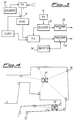
- a first element located on board the vehicle and called localizer hereafter, essentially includes the following members: a transmitter 1, revolving in an essentially horizontal plane, whose revolution is precisely controlled by a clock 2, e.g. a quartz clock, and detected by a synchronizer 3, at least in one point. Both members 2 and 3 supply a signal to a processing unit 4, which receives a further signal from a decoder 5 receiving the signal picked up by a receiver 6. The group of data supplied to unit 4 allows it to provide as an output the position of the vehicle on which the localizer shown in fig.1 is mounted, as it will be explained further on.
- a second element of the device fixed on the perimeter of the operation area and called active reflector hereafter, essentially including the following members: a receiver 7 connected to a signal generator 8 provided with a transmitter 9.
- a decoder 10 will also be present between members 7 and 8. If needed, said decoder 10 can send out a signal also to a net controller 11 connecting it to a local area network (LAN) for the purpose which will be made clear later on.
- LAN local area network
- the revolving transmitter 1 emits a continuous electromagnetic signal which can range from radio waves, to infrared and visible light. This signal is of the directional type, having a beam width limited both in the horizontal and vertical directions.
- the revolving speed of transmitter 1 defines the frequency of calculation of the vehicle position, and therefore may be adapted to the operating conditions and first of all to the travel speed.
- the emission of a laser beam in the visible or infrared band, with a horizontal width ⁇ 1°, a vertical width between 1° and 5°, and a revolving speed of 1 rev/sec, simply obtained by mechanically revolving transmitter 1 at a constant speed. Consequently, the laser beam emitted by the localizer sweeps the whole horizon at every second and during the revolution hits the receivers 7 (in this case photodetectors) of the active reflectors which are within the field of vision. Since the beam has a limited vertical width, it is obvious that the height of transmitter 1 must be near to that of receivers 7.
- receiver 7 When receiver 7 picks up the passage of the laser beam emitted by transmitter 1, it sends an impulse to the signal generator 8 so that the latter emits a reply signal by means of transmitter 9.
- This signal emitted by the active reflector is not of the directional type but diffused, and it contains a code which unambiguously identifies the source of emission, i.e. it contains the "name" of the reflector.
- the duration of the signal is very short, in the range of some ms, but sufficient to modulate the reflector's code and an error detection/correction code.
- Receiver 6 located on the vehicle picks up the signal emitted by the reflector and identifies the activated reflector by means of decoder 5, and then supplies said information to the processing unit 4. When said information is received by processor 4, it is combined with the time indicated by clock 2 and the reference point along the revolution obtained from synchronizer 3, so as to convert the time into an angle with respect to the vehicle axis.
- each revolution processor 4 receives the information about the angles under which the active reflectors located in the field of vision are seen. Therefore, it can perform a triangulation, usually on redundant data, for precisely determining the vehicle position on the base of the map of said reflectors contained in its memory. For example, if the reference point from synchronizer 3 coincides with the 0° direction and clock 2 indicates 0.25 seconds, this means that the reply signal arrived from the 90° direction, i.e.
- the localizer will always have enough active reflectors in its field of vision to obtain a sufficient amount of data for determining the position, even in the presence of disturbances preventing the activation of some reflectors and/or the reception of some replies.
- the "active" reply of the reflector allows the operation also at a distance greater than that allowed by the mere "passive" reading of the reference points.
- the above-described embodiment is clearly just an example susceptible of various modifications.
- the mechanical apparatus for revolving transmitter 1 may be replaced, for example, by an electromagnetic apparatus which varies the signal direction of emission.
- the revolving speed of transmitter 1 is not necessarily constant, though this increases the precision. For example, it could be adapted to the travel speed of the vehicle so as to carry out the position calculation at constant travel intervals.
- a further member may be provided suitable to break off the supply to transmitter 1 during the vehicle stops so as to increase the endurance thereof.
- the precision of the apparatus may be further increased by detecting with a higher frequency the position of the revolving transmitter 1 by means of a synchronizer 3 which carries out, for example, four detections at each revolution, or even by continuously detecting it directly from the revolving mechanism.
- a laser beam is preferably employed because it has a frequency higher than a radio signal thus obtaining a "cleaner" signal, less subject to interferences by electronic apparatuses and the like, which can be modulated at a higher frequency, therefore in a shorter time.
- signals in the band of radio waves or visible light can be employed, and the reply signal of the reflector is not necessarily of the same kind of the localizer signal which activated it.
- the important thing is the compatibility between the two transmitter/receiver pairs 1/7 and 9/6 which exchange signals. Ultrasonic signals do not produce satisfying results, for their greater slowness and the poor propagation characteristics.
- the limited horizontal width is useful to achieve a greater precision, in that a vertical "blade" having an horizontal width or 1° or less allows an exact determination of the time at which receiver 7 of the reflector is hit by the signal from the localizer.
- the lower limit of the beam horizontal width is given by the combination with the revolving speed of transmitter 1, since the time of passage across the receiver must be sufficient for the latter to read the signal.
- a localizer for operating in the presence of a plurality of vehicles simultaneously moving in the same operation area.
- This version of the localizer includes an encoder 12 which allows the modulation of the signal emitted by transmitter 1 so that said signal also contains the code of the emitting vehicle, in addition to the error detection/correction code as in the case of the signal emitted by the reflector.
- the active reflectors are provided with a decoder 10 (fig.2), as mentioned above, which decodes the localizer code in the signal picked up by receiver 7. This information is supplied to generator 8 so that the reflector emits a reply signal containing not only its own identification code but also the code of the localizer which activated it.
- each localizer can ascertain, still by means of decoder 5, whether the picked reply concerns one of its signals or that of another localizer. Decoder 5 can also verify the overlap of signals in the very rare cases, thanks to the duration of the reflector reply, in which two reflectors simultaneously have been activated and have replied to two different localizers. In such an instance, the signal will be simply neglected and not used for determining the position.
- the signals received by a localizer but concerning other vehicles may be simply ignored, or they can be used for determining the position of the other vehicles present in the same area by means of a specific processor 13. However, this determination of the other positions is obtained with a rougher approximation, since the localizer does not have precise information about the revolving speed of the other transmitters and the movements of the other vehicles.
- each active reflector located along the perimeter of said area can be provided with a net controller 11 (fig.2) which connects it to a local network.
- a central processor can obtain the map of the positions of the various vehicles, with a certain approximation in this case too.
- the localizer can also employ the data coming from an odometer 14, which are processed into a processor 15 in combination with the output of processor 4. In this way, the best estimate of the position is obtained, even in case of scarce or redundant information.
- the presence of odometer 14 allows a useful exploitation of only two or even one reply.
- Odometer 14 provides a further advantage in the initial setting up in case the localizer already has a map of the operation environment. In fact, in such a case it is possible to perform the self-calibration of the device instead of supplying the map of the reflectors obtained through an expensive and delicate survey procedure for determining the position of said reflectors.
- the vehicle carries out initial exploration movements in which the odometry is capable of providing very precise data which can be extrapolated, e.g. along a straight line, and the map of the positions of the reflectors is calculated on the basis of these data.
- fig.4 schematically shows how an adequate distribution of active reflectors 16 allows each localizer 17 to have always three to five of them in its field of vision, even in operation areas having a shape much more complicated than a simple rectangular room.
- said energy source consists in batteries which make the vehicle completely independent from the environment wherein it moves.
- the active reflectors may be supplied by batteries, or they may be directly connected to the electrical network, especially if they are connected to a local network.
Landscapes
- Engineering & Computer Science (AREA)
- Physics & Mathematics (AREA)
- Radar, Positioning & Navigation (AREA)
- Remote Sensing (AREA)
- Electromagnetism (AREA)
- Computer Networks & Wireless Communication (AREA)
- General Physics & Mathematics (AREA)
- Control Of Position, Course, Altitude, Or Attitude Of Moving Bodies (AREA)
- Automatic Assembly (AREA)
- Warehouses Or Storage Devices (AREA)
- Radar Systems Or Details Thereof (AREA)
- Body Structure For Vehicles (AREA)
- Steering Controls (AREA)
- Vehicle Body Suspensions (AREA)
- Measurement Of Velocity Or Position Using Acoustic Or Ultrasonic Waves (AREA)
Applications Claiming Priority (2)
| Application Number | Priority Date | Filing Date | Title |
|---|---|---|---|
| ITMI931708 | 1993-07-29 | ||
| ITMI931708A IT1272491B (it) | 1993-07-29 | 1993-07-29 | Metodo per il rilevamento della posizione di un veicolo mobile in un' aerea delimitata e dispositivo che realizza tale metodo |
Publications (2)
| Publication Number | Publication Date |
|---|---|
| EP0636902A1 true EP0636902A1 (de) | 1995-02-01 |
| EP0636902B1 EP0636902B1 (de) | 1999-05-19 |
Family
ID=11366726
Family Applications (1)
| Application Number | Title | Priority Date | Filing Date |
|---|---|---|---|
| EP94830383A Expired - Lifetime EP0636902B1 (de) | 1993-07-29 | 1994-07-26 | Verfahren zum Bestimmen des Ortes eines sich bewegenden Fahrzeuges in einem begrenzten Raum und Vorrichtung zur Durchführung dieses Verfahrens |
Country Status (5)
| Country | Link |
|---|---|
| EP (1) | EP0636902B1 (de) |
| AT (1) | ATE180331T1 (de) |
| DE (1) | DE69418544T2 (de) |
| ES (1) | ES2133522T3 (de) |
| IT (1) | IT1272491B (de) |
Citations (3)
| Publication number | Priority date | Publication date | Assignee | Title |
|---|---|---|---|---|
| EP0185816A1 (de) * | 1984-12-27 | 1986-07-02 | THE GENERAL ELECTRIC COMPANY, p.l.c. | Fahrzeugführungs- und Steuersystem |
| US4837575A (en) * | 1985-11-04 | 1989-06-06 | Motorola, Inc. | Identification system |
| EP0341890A2 (de) * | 1988-05-13 | 1989-11-15 | Cegelec Controls Ltd. | Automatische Fahrzeugsteuerung |
-
1993
- 1993-07-29 IT ITMI931708A patent/IT1272491B/it active IP Right Grant
-
1994
- 1994-07-26 ES ES94830383T patent/ES2133522T3/es not_active Expired - Lifetime
- 1994-07-26 EP EP94830383A patent/EP0636902B1/de not_active Expired - Lifetime
- 1994-07-26 AT AT94830383T patent/ATE180331T1/de not_active IP Right Cessation
- 1994-07-26 DE DE69418544T patent/DE69418544T2/de not_active Expired - Lifetime
Patent Citations (3)
| Publication number | Priority date | Publication date | Assignee | Title |
|---|---|---|---|---|
| EP0185816A1 (de) * | 1984-12-27 | 1986-07-02 | THE GENERAL ELECTRIC COMPANY, p.l.c. | Fahrzeugführungs- und Steuersystem |
| US4837575A (en) * | 1985-11-04 | 1989-06-06 | Motorola, Inc. | Identification system |
| EP0341890A2 (de) * | 1988-05-13 | 1989-11-15 | Cegelec Controls Ltd. | Automatische Fahrzeugsteuerung |
Also Published As
| Publication number | Publication date |
|---|---|
| IT1272491B (it) | 1997-06-23 |
| ATE180331T1 (de) | 1999-06-15 |
| DE69418544D1 (de) | 1999-06-24 |
| ES2133522T3 (es) | 1999-09-16 |
| DE69418544T2 (de) | 1999-11-25 |
| EP0636902B1 (de) | 1999-05-19 |
| ITMI931708A0 (it) | 1993-07-29 |
| ITMI931708A1 (it) | 1995-01-29 |
Similar Documents
| Publication | Publication Date | Title |
|---|---|---|
| EP2256573B1 (de) | Lokalisierungssystem | |
| US6799099B2 (en) | Material handling systems with high frequency radio location devices | |
| US6504610B1 (en) | Method and system for positioning an autonomous mobile unit for docking | |
| JP6973393B2 (ja) | 移動体誘導システム、移動体、誘導装置およびコンピュータプログラム | |
| EP1983397B1 (de) | Landmarkennavigation für Fahrzeuge über blinkende optische Baken | |
| US7054716B2 (en) | Sentry robot system | |
| US7860608B2 (en) | Method and apparatus for generating and tracing cleaning trajectory of home cleaning robot | |
| US5682313A (en) | Method for localization of beacons for an autonomous device | |
| JP2741403B2 (ja) | 自動式車両制御方法 | |
| US20070024845A1 (en) | Measuring device and measuring method for determining distance and/or position | |
| JP6662454B2 (ja) | 移動体誘導システム、移動体、誘導装置およびコンピュータプログラム | |
| DK169003B1 (da) | Fremgangsmåde til navigering af et førerløst køretøj | |
| Dobrev et al. | Steady delivery: Wireless local positioning systems for tracking and autonomous navigation of transport vehicles and mobile robots | |
| US5652593A (en) | Method and apparatus for guiding a machine | |
| EP0193985A1 (de) | Navigationssystem für ein nicht an eine Bahn gebundenes Fahrzeug | |
| EP2278357A2 (de) | Verfahren und Vorrichtung zur Bestimmung der Position eines Fahrzeugs zum autonomen Fahren eines Fahrzeugs, insbesondere eines computergesteuerten Fahrzeugs | |
| CN102135609B (zh) | 一种便携式定位系统 | |
| EP0701701B1 (de) | Verfahren zur bestimmung der genauen position eines frei beweglichen mobilen fahrzeuges und gerat zur anwendung dieses verfahrens fur die fahrzeugfernsteuerung | |
| CN106197396B (zh) | 一种基于光学信号发射和接收的定位导引系统及方法 | |
| EP0636902B1 (de) | Verfahren zum Bestimmen des Ortes eines sich bewegenden Fahrzeuges in einem begrenzten Raum und Vorrichtung zur Durchführung dieses Verfahrens | |
| EP1746477A2 (de) | System zum Führen eines beweglichen Objekts | |
| CN1879036B (zh) | 定位装置、特别是分批箱(batch box)定位系统,识别单元及用于确定位置的方法 | |
| JP3404151B2 (ja) | 位置認識システム | |
| Seki et al. | Positioning system for indoor mobile robot using active ultrasonic beacons | |
| RU2189053C2 (ru) | Способ определения местоположения подвижного объекта |
Legal Events
| Date | Code | Title | Description |
|---|---|---|---|
| PUAI | Public reference made under article 153(3) epc to a published international application that has entered the european phase |
Free format text: ORIGINAL CODE: 0009012 |
|
| AK | Designated contracting states |
Kind code of ref document: A1 Designated state(s): AT CH DE ES FR GB LI NL SE |
|
| 17P | Request for examination filed |
Effective date: 19950726 |
|
| 17Q | First examination report despatched |
Effective date: 19970428 |
|
| GRAG | Despatch of communication of intention to grant |
Free format text: ORIGINAL CODE: EPIDOS AGRA |
|
| GRAG | Despatch of communication of intention to grant |
Free format text: ORIGINAL CODE: EPIDOS AGRA |
|
| GRAH | Despatch of communication of intention to grant a patent |
Free format text: ORIGINAL CODE: EPIDOS IGRA |
|
| GRAH | Despatch of communication of intention to grant a patent |
Free format text: ORIGINAL CODE: EPIDOS IGRA |
|
| GRAA | (expected) grant |
Free format text: ORIGINAL CODE: 0009210 |
|
| AK | Designated contracting states |
Kind code of ref document: B1 Designated state(s): AT CH DE ES FR GB LI NL SE |
|
| PG25 | Lapsed in a contracting state [announced via postgrant information from national office to epo] |
Ref country code: SE Free format text: THE PATENT HAS BEEN ANNULLED BY A DECISION OF A NATIONAL AUTHORITY Effective date: 19990519 Ref country code: AT Free format text: LAPSE BECAUSE OF FAILURE TO SUBMIT A TRANSLATION OF THE DESCRIPTION OR TO PAY THE FEE WITHIN THE PRESCRIBED TIME-LIMIT Effective date: 19990519 |
|
| REF | Corresponds to: |
Ref document number: 180331 Country of ref document: AT Date of ref document: 19990615 Kind code of ref document: T |
|
| REG | Reference to a national code |
Ref country code: CH Ref legal event code: EP |
|
| REF | Corresponds to: |
Ref document number: 69418544 Country of ref document: DE Date of ref document: 19990624 |
|
| ET | Fr: translation filed | ||
| REG | Reference to a national code |
Ref country code: CH Ref legal event code: NV Representative=s name: ABATRON-PATENTBUERO AG |
|
| REG | Reference to a national code |
Ref country code: ES Ref legal event code: FG2A Ref document number: 2133522 Country of ref document: ES Kind code of ref document: T3 |
|
| PLBE | No opposition filed within time limit |
Free format text: ORIGINAL CODE: 0009261 |
|
| STAA | Information on the status of an ep patent application or granted ep patent |
Free format text: STATUS: NO OPPOSITION FILED WITHIN TIME LIMIT |
|
| 26N | No opposition filed | ||
| REG | Reference to a national code |
Ref country code: GB Ref legal event code: IF02 |
|
| PGFP | Annual fee paid to national office [announced via postgrant information from national office to epo] |
Ref country code: CH Payment date: 20130719 Year of fee payment: 20 Ref country code: ES Payment date: 20130729 Year of fee payment: 20 Ref country code: NL Payment date: 20130719 Year of fee payment: 20 Ref country code: DE Payment date: 20130722 Year of fee payment: 20 |
|
| PGFP | Annual fee paid to national office [announced via postgrant information from national office to epo] |
Ref country code: GB Payment date: 20130719 Year of fee payment: 20 Ref country code: FR Payment date: 20130722 Year of fee payment: 20 |
|
| REG | Reference to a national code |
Ref country code: DE Ref legal event code: R071 Ref document number: 69418544 Country of ref document: DE |
|
| REG | Reference to a national code |
Ref country code: DE Ref legal event code: R071 Ref document number: 69418544 Country of ref document: DE |
|
| REG | Reference to a national code |
Ref country code: CH Ref legal event code: PL |
|
| REG | Reference to a national code |
Ref country code: NL Ref legal event code: V4 Effective date: 20140726 |
|
| REG | Reference to a national code |
Ref country code: GB Ref legal event code: PE20 Expiry date: 20140725 |
|
| PG25 | Lapsed in a contracting state [announced via postgrant information from national office to epo] |
Ref country code: DE Free format text: LAPSE BECAUSE OF EXPIRATION OF PROTECTION Effective date: 20140729 |
|
| REG | Reference to a national code |
Ref country code: ES Ref legal event code: FD2A Effective date: 20141120 |
|
| PG25 | Lapsed in a contracting state [announced via postgrant information from national office to epo] |
Ref country code: GB Free format text: LAPSE BECAUSE OF EXPIRATION OF PROTECTION Effective date: 20140725 |
|
| PG25 | Lapsed in a contracting state [announced via postgrant information from national office to epo] |
Ref country code: ES Free format text: LAPSE BECAUSE OF EXPIRATION OF PROTECTION Effective date: 20140727 |