EP0636852A1 - Artillery rocket using canard fins for guiding - Google Patents
Artillery rocket using canard fins for guiding Download PDFInfo
- Publication number
- EP0636852A1 EP0636852A1 EP94110495A EP94110495A EP0636852A1 EP 0636852 A1 EP0636852 A1 EP 0636852A1 EP 94110495 A EP94110495 A EP 94110495A EP 94110495 A EP94110495 A EP 94110495A EP 0636852 A1 EP0636852 A1 EP 0636852A1
- Authority
- EP
- European Patent Office
- Prior art keywords
- rocket
- flight controller
- missile
- missile according
- rudder
- Prior art date
- Legal status (The legal status is an assumption and is not a legal conclusion. Google has not performed a legal analysis and makes no representation as to the accuracy of the status listed.)
- Granted
Links
- 241000272517 Anseriformes Species 0.000 title claims abstract description 13
- 230000007935 neutral effect Effects 0.000 claims description 2
- 230000007704 transition Effects 0.000 abstract description 2
- 238000001514 detection method Methods 0.000 description 2
- 238000004519 manufacturing process Methods 0.000 description 2
- 230000000087 stabilizing effect Effects 0.000 description 2
- 235000015842 Hesperis Nutrition 0.000 description 1
- 235000012633 Iberis amara Nutrition 0.000 description 1
- 230000008859 change Effects 0.000 description 1
- 238000011161 development Methods 0.000 description 1
- 230000018109 developmental process Effects 0.000 description 1
- 238000010586 diagram Methods 0.000 description 1
- 230000000694 effects Effects 0.000 description 1
- 230000000977 initiatory effect Effects 0.000 description 1
- 238000009434 installation Methods 0.000 description 1
- 230000010354 integration Effects 0.000 description 1
- 230000007246 mechanism Effects 0.000 description 1
- 230000009467 reduction Effects 0.000 description 1
- 230000000717 retained effect Effects 0.000 description 1
- 238000009420 retrofitting Methods 0.000 description 1
- 239000000523 sample Substances 0.000 description 1
- 239000007787 solid Substances 0.000 description 1
- 210000002435 tendon Anatomy 0.000 description 1
Images

Classifications
-
- F—MECHANICAL ENGINEERING; LIGHTING; HEATING; WEAPONS; BLASTING
- F42—AMMUNITION; BLASTING
- F42B—EXPLOSIVE CHARGES, e.g. FOR BLASTING, FIREWORKS, AMMUNITION
- F42B10/00—Means for influencing, e.g. improving, the aerodynamic properties of projectiles or missiles; Arrangements on projectiles or missiles for stabilising, steering, range-reducing, range-increasing or fall-retarding
- F42B10/60—Steering arrangements
- F42B10/62—Steering by movement of flight surfaces
- F42B10/64—Steering by movement of flight surfaces of fins
Definitions
- the invention relates to an artillery rocket according to the preamble of claim 1.
- Such a missile is introduced in the western world as the MLRS base missile for ballistic deployment of submunition warheads over a predetermined target area.
- the azimuth and elevation of the rocket's stowage and launch container determine the direction and distance to the target area during its ejection, which is followed by a short boost phase to accelerate into a ballistic trajectory, over which a time-liner programmed for a flight path determines a gas generator for ejecting the submunition warhead fires from the launch vehicle.
- the invention is therefore based on the object of increasing the precision of a rocket of the generic type while maintaining the system components introduced.
- the rocket is equipped with a flight controller, the technical complexity of which can be kept comparatively low because it is supported by a precise radio navigation system that not only provides a reference for the current orbit coordinates, but in particular also for the location and time of the payload delivery .
- the flight controller works on an actuating system that is located in front of the warhead in the front area of the ogive, without the usable one Noticeably restrict the volume of the warhead.
- the design of the rocket in the area of their rocket motor remains completely unaffected by the fact that the rudders on which the flight controller works are designed as comparatively strongly extended canards in the longitudinal direction of the rocket. Their small span enables them to be accommodated in the rocket's stowage and launch container without resorting to complex folding mechanisms to have to.
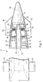
- the basic missile 11 of the MLRS artillery system (also as the medium one) which was introduced in the western world Artillery Missile System called MARS) (which does not appear visually as a result of the interrupted representation of FIG. 1) is a very slim, that is to say very long in relation to its diameter.
- the rocket 11 By means of its solid rocket motor 12, which extends approximately over the rear half of the missile length, the rocket 11 is accelerated in the order of magnitude of two seconds immediately after it has been ejected from the storage and launching container, in order then to be without drive on the ballistic path over the predetermined one
- the missile 11 is equipped according to the invention with an active inertial trajectory control system 13, to which a target trajectory is predefined in the target coordinates at the start and which can thereby correct influences of errors when approaching the target area, in particular on departure disorders and on disturbing wind influences decrease, which lead to an offset of the ballistic trajectory 14 (FIG. 3) in the case of an uncorrected flight.
- the active flight path control system 13 enables the position to be kept and the position controlled during the entire flight mission, with the detection of any deviations from the desired flight path and the correction of errors that have occurred by means of the flight controller 15, which, with the information about the control deviation 16 (FIG. 2), compensates for this on a control system 17 acts on the missile 11.
- the rocket 11 is also equipped with a roll position sensor 18 for acting on the flight controller 15.
- An initialization computer 19 transmits the specified target values with regard to the flight path and delivery point and the current actual values with respect to the flight controller 15 immediately before the launch of the rocket 11 Operating variables such as start coordinates and start elevation as well as current disturbance variables such as manufacturing-related misdirection when starting from the container and current cross wind strength.
- a radio-based navigation system such as ibs. of a global positioning system (GPS) receiver 20 in the function of the flight path control system 13 with the inertial flight controller 15 allows the ignition point for the initiation of the gas generator 21 for the lateral ejection of the payload with regard to the time period from the start of the rocket 11 and / or to determine very precisely with regard to the location coordinates of the target area reached by the flight path 14 and thus to achieve high precision in the defined payload delivery that would not be achievable with an autonomous runtime control from the rocket launch.
- GPS global positioning system
- the entire trajectory control system 13, including electrical energy supply 22 and actuating system 17, is integrated into the front section of the ogive of the missile 11 between the warhead and the gas generator 21 in the space immediately behind the front frame 23 and takes up only a minimal payload space there in comparison to the conventional equipment of the MLRS Basic rocket 11.
- the front main frame 23, which connects the gas generator section to the warhead shell, is thus retained in its form and function completely, but is incorporated as an integral part in the structural implementation of the additionally installed trajectory control system 13, especially with regard to the Storage of the control system 17 (see below).
- the flight controller 15 including the inertial package (consisting of pitch and yaw rate gyros, roll position sensor 18, navigation receiver 20, and data processing) and the energy supply 22 in the conically widening section of the ogive.
- the implementation effort for the inertial flight controller 15 can be kept comparatively low despite increased demands on the delivery accuracy, since it is updated with precise actual position coordinates from the GPS receiver 20 during the flight of the rocket 11 and the current flight speed is also always very high can be determined exactly from the GPS information (change in position over the system time difference).
- the stabilizing fins 24 emerging at the tail of the rocket 11 after leaving the start canister are not readily available for retrofitting to control the flight path because the articulation area of the rocket motor 12 intervenes in this area should be.
- the mechanically highly stressable area behind the front main frame 23 in the ogive of the missile 11 is selected for the positioning system storage, as a result of which the control rudders 25 are realized as canards.
- the rear stabilizing flaps 24, which are spring-loaded only after the start, are mounted without employment.
- the canard rudders 25 also have no position when the start is as swirl-free as possible in order to first fly through the undisturbed ballistic path 14 (left in FIG. 3) during and after the boost phase.
- the height h of the railway apogee 34 which depends on the elevation e, this would lead to a range R which can only be varied to a limited extent and, if the start is too steep, even reduced.
- the rudders 25 are turned on by the flight path control system 13 after apogee 34 has been reached in order to intervene correctively in the path, then the originally ballistic flight path 14 is left because the lifting effect of the now turned rudders 25 leads to an elongated path 14 'and thus to one Increasing the distance d leads to approximately twice the range 2R (FIG. 3). Because of the aerodynamic buoyancy of the canard rudders 25, the rocket 11 then flies along the latter with an almost constant glide angle precisely over the target area specified in terms of coordinates.
- the radial dimensions of the canard oars 25 in the conically tapering ogive area in front of the warhead do not require expensive folding wings, because the clear width of the storage and launch container is sufficient to accommodate sufficiently protruding canard wings.
- the control system 17 is not yet active during the boost phase. Then the rocket 11 is accelerated to multiple speeds of sound, but this is not a problem for the canard rudders 25 because they do not have to be unfolded first, but are held in their functional position without play.
Landscapes
- Physics & Mathematics (AREA)
- Fluid Mechanics (AREA)
- Engineering & Computer Science (AREA)
- General Engineering & Computer Science (AREA)
- Radar Systems Or Details Thereof (AREA)
- Aiming, Guidance, Guns With A Light Source, Armor, Camouflage, And Targets (AREA)
Abstract
Description
Die Erfindung betrifft eine Artillerie-Rakete gemäß dem Oberbegriff des Anspruches 1.The invention relates to an artillery rocket according to the preamble of claim 1.
Eine solche Rakete ist in der westlichen Welt als die MLRS-Basisrakete zum ballistischen Verbringen von Submunitions-Gefechtsköpfen über ein vorgegebenes Zielgebiet eingeführt. Azimut und Elevation des Stau- und Startbehälters der Rakete bestimmen bei ihrem Ausstoß, auf den eine kurze Boost-Phase zur Beschleunigung in eine ballistische Flugbahn folgt, Richtung und Distanz zum Zielgebiet, über dem ein flugbahnabhängig programmierter Zeitzünder einen Gasgenerator zum Ausstoßen des Submunitions-Gefechtskopfes aus der Trägerrakete zündet. Systembedingte Fehler, insoweit sie überhaupt quantitativ erfaßbar sind, können nur vor dem Raketenstart berücksichtigt werden; wie etwa ein fertigungsbedingter individueller Abgangsfehler der jeweiligen Rakete oder die momentanen Boden-Querwindeinflüsse, die mittels einer Sonde gemäß DE-OS 41 20 367 ermittelbar sind. Aber auch solche Störgrößen-Berücksichtigung ist fehleranfällig, und Störeinflüsse beim Durchfliegen der ballistischen Bahn nach dem Start können gar nicht mehr berücksichtigt werden. Daraus resultiert eine gewisse Ungenauigkeit bei der Abgabe der Nutzlast über dem vorbestimmten Zielgebiet, die insofern hinnehmbar ist, als es sich bei der eingeführten Nutzlast um Streumunition (Bomblets und Streuminen) handelt. Gerade deshalb ist allerdings der Einsatz dieser eingeführten ballistisch fliegenden Artillerie-Rakete in verzahnten Konfliktgebieten kaum vertretbar, weil es dort auf sehr präzise Bekämpfung definierter Zielgebiete ankommt.Such a missile is introduced in the western world as the MLRS base missile for ballistic deployment of submunition warheads over a predetermined target area. The azimuth and elevation of the rocket's stowage and launch container determine the direction and distance to the target area during its ejection, which is followed by a short boost phase to accelerate into a ballistic trajectory, over which a time-liner programmed for a flight path determines a gas generator for ejecting the submunition warhead fires from the launch vehicle. System-related errors, insofar as they can be recorded quantitatively, can only be taken into account before the rocket is launched; such as a manufacturing-related individual departure error of the respective rocket or the current ground cross-wind influences, which can be determined by means of a probe according to DE-OS 41 20 367. However, such disturbance variables are also susceptible to errors, and disturbances when flying through the ballistic trajectory after take-off can no longer be taken into account. This results in a certain inaccuracy in the delivery of the payload over the predetermined target area, which is acceptable insofar as it is with the introduced payload cluster munitions (bomblets and cluster mines). Precisely for this reason, however, the use of this ballistic flying artillery missile in interlocking conflict areas is hardly justifiable because it is very important to combat defined target areas there.
In Erkenntnis dieser Gegebenheiten liegt der Erfindung deshalb die Aufgabe zugrunde, eine Rakete gattungsgemäßer Art unter Beibehaltung der eingeführten Systemkomponenten in ihrer Präzision zu steigern.In recognition of these circumstances, the invention is therefore based on the object of increasing the precision of a rocket of the generic type while maintaining the system components introduced.
Diese Aufgabe ist bei einer gattungsgemäßen Rakete dadurch gelöst, daß sie gemäß den Merkmalen des Patentanspruches 1 ausgestattet ist.This object is achieved in a generic rocket in that it is equipped according to the features of claim 1.
Nach dieser Lösung wird die Rakete mit einem Flugregler ausgestattet, dessen technischer Aufwand vergleichsweise gering gehalten bleiben kann, weil er aus einem präzisen Funknavigationssystem gestützt wird, das nicht nur eine Referenz für die aktuellen Bahnkoordinaten, sondern insbesondere auch für Ort bzw. Zeitpunkt der Nutzlastabgabe liefert.According to this solution, the rocket is equipped with a flight controller, the technical complexity of which can be kept comparatively low because it is supported by a precise radio navigation system that not only provides a reference for the current orbit coordinates, but in particular also for the location and time of the payload delivery .
Um nicht nur ohne wesentliche Eingriffe in das eingeführte MLRS-System, sondern auch ohne gravierende Eingriffe in die Struktur der Basisrakete diese Präzisionssteigerung zu erreichen, arbeitet der Flugregler auf ein Stellsystem, das vor dem Gefechtskopf im vorderen Bereich der Ogive untergebracht ist, ohne das nutzbare Volumen für den Gefechtskopf spürbar einzuschränken. Die Raktenauslegung im Bereiche ihres Raketenmotors bleibt also völlig unbeeinflußt, indem die Ruder, auf die der Flugregler arbeitet, als vergleichsweise stark in Raketen-Längsrichtung gestreckte Canards ausgelegt sind. Deren geringe Spannweite ermöglicht die Unterbringung im Stau- und Startkontainer der Rakete, ohne auf konstruktiv aufwendige Klappmechanismen zurückgreifen zu müssen. Wenn die Canard-Ruder nach Durchfliegen des ballistischen Apogäums aus ihrer anfänglichen neutralen Stellung angestellt werden, um vom Flugregler ermittelte Bahnkorrekturen für das zuverlässige Erreichen der vorgegebenen zielkoordinaten zu ermöglichen, ergibt sich dadurch ein zusätzlicher aerodynamischer Auftrieb, der zu einer Streckung der Bahnkurve und dadurch zusätzlich zur Präzisionssteigerung auch noch zu einer wesentlichen Reichweitensteigerung führt, so daß die daraus resultierende Senkung der logistischen Kosten den höheren Ausstattungsaufwand der Basisrakete weit überkompensiert.In order to achieve this increase in precision not only without significant interventions in the introduced MLRS system, but also without serious interventions in the structure of the base rocket, the flight controller works on an actuating system that is located in front of the warhead in the front area of the ogive, without the usable one Noticeably restrict the volume of the warhead. The design of the rocket in the area of their rocket motor remains completely unaffected by the fact that the rudders on which the flight controller works are designed as comparatively strongly extended canards in the longitudinal direction of the rocket. Their small span enables them to be accommodated in the rocket's stowage and launch container without resorting to complex folding mechanisms to have to. If the canard rudders are turned from their initial neutral position after flying through the ballistic apogee in order to enable the flight controller to determine the corrected path for reliably reaching the specified target coordinates, this results in additional aerodynamic lift, which leads to a stretching of the path curve and thereby additionally the increase in precision also leads to a substantial increase in range, so that the resulting reduction in logistic costs more than compensates for the higher outlay on the basic rocket.
Zusätzliche Alternativen und Weiterbildungen sowie weitere Merkmale und Vorteile der Erfindung ergeben sich aus den weiteren Ansprüchen und, auch unter Berücksichtigung der Darlegungen in der Zusammenfassung, aus nachstehender Beschreibung eines in der Zeichnung unter Beschränkung auf das Wesentliche nicht ganz maßstäblich und stark abstrahiert skizzierten bevorzugten Realisierungsbeispiels zur erfindungsgemäßen Lösung. In der Zeichnung zeigt:
- Fig. 1
- in unterbrochener Darstellung, teilweise als Axial-Längsschnitt, eine mit satellitennavigationsgestütztem Flugregler für die Ansteuerung von Canard-Rudern ausgestattete Rakete,
- Fig. 2
- im Blockschaltbild eine stark vereinfachte Lenkschleife für eine typische Steuerung der erfindungsgemäß ausgestatteten Rakete nach Fig. 1 und
- Fig. 3
- das Flugbahnprofil über der Reichweite in Abhängigkeit von der Startelevation der Rakete mit einer Flugbahn-Beeinflussung etwa gemäß Fig. 2.
- Fig. 1
- in interrupted representation, partially as an axial longitudinal section, a rocket equipped with satellite navigation-supported flight controller for the control of canard oars,
- Fig. 2
- in the block diagram a greatly simplified steering loop for a typical control of the missile equipped according to the invention according to FIGS. 1 and
- Fig. 3
- the trajectory profile over the range as a function of the launch elevation of the rocket with a trajectory influence, for example according to FIG. 2.
Bei der Basis-Rakete 11 des in der westlichen Welt eingeführten MLRS-Artillerieraketensystems (auch als mittleren Artillerieraketensystem MARS bezeichnet) handelt es sich (was infolge der unterbrochenen Darstellung der Fig. 1 visuell nicht in Erscheinung tritt) um einen sehr schlanken, also im Verhältnis zu seinem Durchmesser sehr langen Flugkörper. Mittels seines sich etwa über die rückwärtige Hälfte der Flugkörper-Länge erstreckenden Feststoff-Raketenmotors 12 wird die Rakete 11 unmittelbar nach ihrem Ausstoß aus dem Stau- und Startbehälter in der Größenordnung von kanpp zwei Sekunden lang beschleunigt, um dann antriebslos auf ballistischer Bahn über das vorbestimmte Zielgebiet zu fliegen und dort ihre Wirkkörper (Bomblets, Abwurfminen oder endphasenlenkende Submunitionsflugkörper) durch seitliches Aufbrechen der Raketenhülle abzuliefern.In the case of the
Um dieses vorbestimmte Zielgebiet zuverlässiger zu erreichen, ist die Rakete 11 erfindungsgemäß mit einem aktiven Inertial-Flugbahnsteuersystem 13 ausgestattet, dem beim Start eine Sollflugbahn in die Zielkoordinaten vorgegeben wird und das dadurch beim Anflug auf das Zielgebiet Fehlereinflüsse korrigieren kann, die insbesondere auf Abgangsstörungen und auf störende Windeinflüsse zurückgehen, welche bei unkorrigiertem Flug zu einem Versatz der ballistischen Flugbahn 14 (Fig. 3) führen. Das aktive Flugbahnsteuersystem 13 dagegen ermöglicht eine Lagehaltung und Lageregelung während der gesamten Flugmission unter Feststellung etwaiger Abweichungen von der Sollflugbahn und Korrektur aufgetretener Fehler mittels des Flugreglers 15, der mit der Information über die Regelabweichung 16 (Fig. 2) zu deren Kompensation auf ein Stellsystem 17 an der Rakete 11 einwirkt. Um das Stellsystem 17 für definierte Bewegungen im Raum ansteuern zu können, ist die Rakete 11 ferner mit einem Roll-Lagesensor 18 zur Beaufschlagung des Flugreglers 15 ausgestattet. Ein Initialisierungsrechner 19 überträgt unmittelbar vor dem Start der Rakete 11 in den Flugregler 15 die vorgegebenen Sollwerte hinsichtlich Flugbahn und Ablieferungspunkt sowie die aktuellen Istwerte hinsichtlich Betriebsgrößen wie Startkoordinaten und Startelevation e sowie aktuelle Störgrößen wie fertigungsbedingte Fehlweisung beim Start aus dem Behälter und aktuelle Querwindstärke.In order to reach this predetermined target area more reliably, the
Die Einbindung eines funkgestützten Navigationssystemes wie ibs. eines Global Positioning System- (GPS-)Empfängers 20 in die Funktion des Flugbahnsteuersystemes 13 mit dem Inertial-Flugregler 15 erlaubt es, für die Initiierung des Gasgenerators 21 zum seitlichen Ausstoß der Nutzlast den Zündpunkt hinsichtlich der Zeitspanne ab dem Start der Rakete 11 und/oder hinsichtlich der Ortskoordinaten des von der Flugbahn 14 erreichten Zielgebietes sehr genau zu bestimmen und damit eine hohe Präzision bei der definierten Nutzlast-Ablieferung zu erzielen, wie sie mit einer autonomen Laufzeitsteuerung ab Raketenstart nicht erreichbar wäre.The integration of a radio-based navigation system such as ibs. of a global positioning system (GPS)
Das gesamte Flugbahnsteuersystem 13 einschließlich elektrischer Energieversorgung 22 und Stellsystem 17 ist in die vordere Sektion der Ogive der Rakete 11 zwischen Gefechtskopf und Gasgenerator 21 im Raum unmittelbar hinter dem vorderen Spant 23 integriert und beansprucht dort nur einen minimalen Nutzlastraum im Vergleich zur herkömmlichen Ausstattung der MLRS-Basisrakete 11. Der vordere Haupt-Spant 23, der die Gasgenerator-Sektion mit der Gefechtskopfhülle verbindet, bleibt so in seiner Form und Funktion vollständig erhalten, wird aber als integraler Bestandteil in die strukturelle Realisierung des zusätzlich eingebauten Flugbahnsteuersystemes 13 einbezogen, vor allem hinsichtlich der Lagerung des Stellsystemes 17 (s. unten). Hinter diesem schließen sich der Flugregler 15 samt Inertialpaket (bestehend aus Nick- und Gierraten-Kreiseln, Roll-Lagesensor 18, Navigations-Empfänger 20, und Datenverarbeitung) sowie die Energieversorgung 22 in der konisch sich aufweitenden Sektion der Ogive an.The entire
Der Realisierungs-Aufwand für den Inertial-Flugregler 15 kann trotz erhöhter Anforderungen an die Abliefergenauigkeit vergleichsweise gering gehalten werden, da er während des Fluges der Rakete 11 mit genauen Ist-Positionskoordinaten aus dem GPS-Empfänger 20 aktualisiert wird und auch die aktuelle Fluggeschwindigkeit stets sehr genau aus den GPS-Informationen (Positionsänderung über der Systemzeitdifferenz) ermittelbar ist.The implementation effort for the
Die am Heck der Rakete 11 sich nach dem Verlassen des Startkanisters ausstellenden Stabilisierungsflossen 24 stehen für eine Umrüstung zu Rudern für die Flugbahnbeeinflussung nicht ohne weiteres zur Verfügung, weil dafür in ihrem Anlenkungsbereich in die Konstruktion und somit auch in die Funktion des Raketen-Motors 12 eingegriffen werden müßte. Deshalb wird der mechanisch hoch beanspruchbare Bereich hinter dem vorderen Haupt-Spant 23 in der Ogive der Rakete 11 für die Stellsystem-Lagerung gewählt, wodurch sich die Realisierung der Steuer-Ruder 25 als Canards ergibt. Diese greifen mit Wellenstümpfen 26 in die Ogiven-Hülle 27 radial bezüglich der Raketen-Längsachse 28 hinein und sind dort jeweils vor einem Stellgetriebe 29 auf einem Zapfen 30 gelagert, der von der rohrförmigen Innenstruktur 31 im Gefechtskopf-Bereich der Rakete 11 gehaltert ist.The stabilizing
Im Interesse guten Regelverhaltens und hoher Dynamik sind für das Stellsystem 17 vier unabhängig voneinander ansteuerbare Ruder 25 orthogonal zueinander vorgesehen, und damit vier Servoantriebe 32, die zwischen den Stellgetrieben 29 und einem zusätzlich eingebauten Zwischenspant 33 auf der rohrförmigen Innenstruktur 31 vor dem Elektronikteil montiert sind. Diese Auslegung erlaubt den Einbau kleiner Stellmotore für die Realisierung hoher Stellsystemdynamik für die Nick- und Giersteuerung zusätzlich zur Roll-Lagebeeinflussung der Rakete 11. Eine besonders hohe Zuverlässigkeit auch nach langer Lagerzeit verspricht ein potentiometerfreier Servorantrieb 32 gemäß DE-PS 35 01 156. Für das Stellgetriebe 29 ist wegen der definierten und störungsfreien Hubbegrenzung eine Einrichtung nach der DE-OS 40 19 482 zu bevorzugen.In the interest of good control behavior and high dynamics, four independently
Die rückwärtigen, sich erst nach dem Start federbelastet aufstellenden Stabilisierungsklappen 24 sind ohne Anstellung montiert. Auch die Canard-Ruder 25 weisen beim möglichst drallfreien Start noch keine Anstellung auf, um während und nach der Boost-Phase zunächst die ungestörte ballistische Bahn 14 (in Fig. 3 links) zu durchfliegen. Die würde allerdings je nach der von der Elevation e abhängigen Höhe h des Bahn-Apogäums 34 zu einer nur beschränkt variierbaren und bei zu steilem Start sogar reduzierten Reichweite R führen. Wenn jedoch die Ruder 25 nach Erreichen des Apogäums 34 vom Flugbahnsteuersystem 13 angestellt werden, um korrigierend in die Bahn einzugreifen, dann wird die ursprünglich ballistische Flugbahn 14 verlassen, weil die Auftriebswirkung der nun angestellten Ruder 25 zu einer gestreckten Bahn 14' und damit zu einer Vergrößerung der Distanz d auf etwa die doppelte Reichweite 2R führt (Fig. 3). Längs dieser fliegt dann die Rakete 11 aufgrund des aerodynamischen Auftriebes der Canard-Ruder 25 mit nahezu konstantem Gleitwinkel genau über das koordinatenmäßig vorgegebene Zielgebiet.The rear stabilizing
Die radiale Abmessung der Canard-Ruder 25 im konisch sich verjüngenden Ogiven-Bereich vor dem Gefechtskopf bedingt keine teueren Klappflügel, weil die lichte Weite des Lager- und Startkontainers zur Aufnahme hinreichend ausladender Canard-Flügel ausreicht. Während der Boost-Phase ist das Stellsystem 17 noch nicht aktiv. Danach ist die Rakete 11 auf mehrfache Schallgeschwindigkeit beschleunigt, was aber für die Canard-Ruder 25 unproblematisch ist, weil diese ja nicht erst ausgeklappt werden müssen, sondern schon spielfrei in ihrer Funktionsstellung gehaltert sind. Die im Vergleich zur Gesamtlänge der Rakete 11 geringe Länge der Canard-Ruder 25 bei hoher Pfeilung ihrer Vorderkanten stellt sicher, daß selbst bei hohen Anstellwinkeln zum Übergang von der ballistischen Bahn 14 in die gestreckte Bahn 14' ein Strömungsabriß nicht zu befürchten ist, sondern stabile und reproduzierbare aerodynamische Verhältnisse beibehalten bleiben.The radial dimensions of the
So liefert die höhere Ablieferungs-Präzision dieses an sich als ballistische Rakete eingeführten Waffensystems zugleich in wünschenswerter Weise eine ganz erhebliche Reichweitensteigerung. Das ermöglicht es, den Werfer in sicherere Positionen in größerem Abstand hinter die Front zurückzunehmen und dennoch mit dem gleichen Werfer-Azimutschwenk aufgrund der wesentlich vergrößerten Reichweite einen Sektor mit längerer Sehne im Frontbereich zu überdecken. Daraus wiederum resultiert, daß der seitliche Abstand zwischen einzelnen Werfern vergrößert werden kann, ohne daß Lücken in der Fronterfassung auftreten. Somit sind für vergleichbare Leistungen wegen der höheren Ablieferungsgenauigkeit nicht nur weniger Raketen 11 erforderlich, sondern auch weniger Starteinrichtungen, was die höheren Ausstattungskosten einer solchen präziseren und reichweitengesteigerten Artillerierakete 11 ohne weiteres rechtfertigt.The higher delivery precision of this weapon system, which was introduced as a ballistic missile, also provides a very substantial increase in range. This makes it possible to take the launcher back into the safer positions at a greater distance behind the front and still cover a sector with a longer tendon in the front area with the same launcher azimuth swivel due to the significantly increased range. This in turn means that the lateral distance between individual throwers can be increased without gaps in the front detection. Thus, because of the higher delivery accuracy, not only
Claims (9)
dadurch gekennzeichnet,
die Rakete (11) mit einem Flugregler (15) für die Steuerung eines Ruder-Stellsystemes (17) ausgestattet ist, der aus einem Navigations-Empfänger (20) mit aktuellen Ortskoordinaten aktualisierbar ist.Artillery rocket (11) with an engine (12) for launching into a ballistic trajectory (14) over a predetermined target area over which the payload is to be released,
characterized,
the rocket (11) is equipped with a flight controller (15) for controlling a rudder positioning system (17), which can be updated with current location coordinates from a navigation receiver (20).
dadurch gekennzeichnet,
daß ein drallfreier Start der Rakete (11) vorgesehen ist und dem Flugregler (15) ein Roll-Lagesensor (18) aufgeschaltet ist.Rocket according to claim 1,
characterized,
that a swirl-free start of the rocket (11) is provided and the flight controller (15) has a roll position sensor (18) connected to it.
dadurch gekennzeichnet,
daß der Flugregler (15) samt Ruder-Stellsystem (17), Navigations-Empfänger (20), Lagesensor (18) und Energieversorgung (22) in der Hülle (27) der Raketen-Ogive vor dem Gefechtskopf angeordnet ist.Missile according to claim 1 or 2,
characterized,
that the flight controller (15) together with the rudder positioning system (17), navigation receiver (20), position sensor (18) and energy supply (22) is arranged in the shell (27) of the missile ogive in front of the warhead.
dadurch gekennzeichnet,
daß das Stellsystem (17) samt Stellgetriebe (29) für Ruder (25) zwischen dem vorderen Haupt-Spant (23) der Raketenstruktur und einem zusätzlich eingesetzten Zwischenspant (33) montiert ist.Rocket according to claim 3,
characterized,
that the control system (17) together with the control gear (29) for rudder (25) is mounted between the front main frame (23) of the rocket structure and an additional intermediate frame (33).
dadurch gekennzeichnet,
daß mehrere Canard-Ruder (25) vorgesehen sind.Missile according to one of the preceding claims
characterized,
that several canard oars (25) are provided.
dadurch gekennzeichnet,
daß die Ruder (25) mit Wellenstümpfen (26) in die Hülle (27) radial bezüglich ihrer Längsachse (28) eingreifen.Missile according to one of the preceding claims,
characterized,
that the rudders (25) with stub shafts (26) engage radially with respect to their longitudinal axis (28) in the casing (27).
dadurch gekennzeichnet,
daß mehrere unabhängig voneinander einstellbare Ruder (25) mit eigenen Stellgetrieben (29) vorgesehen sind.Missile according to one of the preceding claims,
characterized,
that several independently adjustable rudders (25) are provided with their own actuators (29).
dadurch gekennzeichnet,
daß in der Startphase eine Übergabe von Zielkoordinaten an den Flugregler (15) und von Startkoordinaten an den Navigations-Empfänger (20) aus einem Initialisierungsrechner (19) zusätzlich zu aktuellen Störgrößeninformationen vorgesehen ist.Missile according to one of the preceding claims,
characterized,
that in the start phase a transfer of target coordinates to the flight controller (15) and of start coordinates to the navigation receiver (20) from an initialization computer (19) is provided in addition to current disturbance variable information.
dadurch gekennzeichnet,
daß der Flugregler (15) dafür ausgelegt ist, erst nach dem Durchfliegen des Apogäums (34) der ballistischen Start-Flugbahn (14) durch Anstellen der Ruder (25) aus der anfänglich neutralen Stellung in eine gestreckte Bahn (14') wesentlich vergrößerter Reichweite (2R) mit nahezu konstantem Gleitwinkel überzugehen.Missile according to one of the preceding claims,
characterized,
that the flight controller (15) is designed only after the apogee (34) has flown through the ballistic take-off trajectory (14) by turning the rudder (25) from the initially neutral position into an elongated path (14 ') with a substantially increased range (2R) with an almost constant glide angle.
Applications Claiming Priority (2)
| Application Number | Priority Date | Filing Date | Title |
|---|---|---|---|
| DE4325218 | 1993-07-28 | ||
| DE4325218A DE4325218C2 (en) | 1993-07-28 | 1993-07-28 | Artillery missile and method for increasing the performance of an artillery missile |
Publications (2)
| Publication Number | Publication Date |
|---|---|
| EP0636852A1 true EP0636852A1 (en) | 1995-02-01 |
| EP0636852B1 EP0636852B1 (en) | 1996-10-02 |
Family
ID=6493850
Family Applications (1)
| Application Number | Title | Priority Date | Filing Date |
|---|---|---|---|
| EP94110495A Expired - Lifetime EP0636852B1 (en) | 1993-07-28 | 1994-07-06 | Artillery rocket using canard fins for guiding |
Country Status (3)
| Country | Link |
|---|---|
| US (1) | US5467940A (en) |
| EP (1) | EP0636852B1 (en) |
| DE (2) | DE4325218C2 (en) |
Cited By (3)
| Publication number | Priority date | Publication date | Assignee | Title |
|---|---|---|---|---|
| DE19624187C1 (en) * | 1996-06-18 | 1998-01-15 | Diehl Gmbh & Co | rocket |
| DE19635847A1 (en) * | 1996-09-04 | 1998-03-12 | Daimler Benz Aerospace Ag | Guided missile with ramjet drive |
| US6685134B2 (en) | 2001-08-22 | 2004-02-03 | Diehl Munitionssystems Gmbh & Co. Kg | Artillery rocket |
Families Citing this family (34)
| Publication number | Priority date | Publication date | Assignee | Title |
|---|---|---|---|---|
| DE19500993A1 (en) * | 1995-01-14 | 1996-07-18 | Contraves Gmbh | Establishing roll attitude of rolling flying object, e.g rocket or other projectile |
| US5775636A (en) * | 1996-09-30 | 1998-07-07 | The United States Of America As Represented By The Secretary Of The Army | Guided artillery projectile and method |
| DE19645496C2 (en) * | 1996-11-05 | 2001-05-17 | Diehl Stiftung & Co | Rocket rotating around its longitudinal axis with satellite navigation receiver |
| US6237496B1 (en) * | 1997-02-26 | 2001-05-29 | Northrop Grumman Corporation | GPS guided munition |
| US5943009A (en) * | 1997-02-27 | 1999-08-24 | Abbott; Anthony Steven | GPS guided munition |
| DE19922693A1 (en) * | 1999-05-18 | 2000-11-23 | Diehl Stiftung & Co | Control device for the rudder of a missile |
| ITMI20010648A1 (en) * | 2001-03-27 | 2002-09-27 | Finmeccanica S P A Alenia Dife | CONTROL GROUP FOR MISSILE AND / OR PROJECTILE DIRECTIONAL FLIGHTS |
| GB0111171D0 (en) * | 2001-05-08 | 2001-06-27 | Special Cartridge Company Ltd | Projictile |
| DE10134785A1 (en) * | 2001-07-17 | 2003-02-06 | Diehl Munitionssysteme Gmbh | Procedure for correcting the trajectory of ballistic missile-stabilized artillery ammunition |
| DE10147837A1 (en) * | 2001-09-27 | 2003-04-24 | Rheinmetall Landsysteme Gmbh | Warhead throwing system with a mine neutralizer |
| DE10236157A1 (en) | 2002-08-07 | 2004-02-26 | Junghans Feinwerktechnik Gmbh & Co. Kg | Fuse for artillery ammunition, comprises infrared interface at its cap, for recording large amounts of data in form of prediction data as initializing information for onboard satellite navigation |
| US6685143B1 (en) * | 2003-01-03 | 2004-02-03 | Orbital Research Inc. | Aircraft and missile forebody flow control device and method of controlling flow |
| US7121210B2 (en) * | 2003-02-18 | 2006-10-17 | Kdi Precision Products, Inc. | Accuracy fuze for airburst cargo delivery projectiles |
| US8661980B1 (en) | 2003-05-08 | 2014-03-04 | Lone Star Ip Holdings, Lp | Weapon and weapon system employing the same |
| US7530315B2 (en) | 2003-05-08 | 2009-05-12 | Lone Star Ip Holdings, Lp | Weapon and weapon system employing the same |
| IL162027A (en) * | 2004-05-17 | 2009-05-04 | Rafael Advanced Defense Sys | Method and system for adjusting the flight path of an unguided projectile, with compensation for jittering deviation of the launcher |
| US7503521B2 (en) * | 2005-02-07 | 2009-03-17 | Bae Systems Information And Electronic Systems Integration Inc. | Radiation homing tag |
| US20080029641A1 (en) * | 2005-02-07 | 2008-02-07 | Bae Systems Information And Electronic Systems | Three Axis Aerodynamic Control of Guided Munitions |
| WO2007089243A2 (en) * | 2005-02-07 | 2007-08-09 | Bae Systems Information And Electronic Systems Integration Inc. | Optically guided munition control system and method |
| US7533849B2 (en) * | 2005-02-07 | 2009-05-19 | Bae Systems Information And Electronic Systems Integration Inc. | Optically guided munition |
| WO2006086528A2 (en) * | 2005-02-07 | 2006-08-17 | Bae Systems Information And Electronic Systems Integration Inc. | Ballistic guidance control for munitions |
| US7690304B2 (en) * | 2005-09-30 | 2010-04-06 | Lone Star Ip Holdings, Lp | Small smart weapon and weapon system employing the same |
| US7895946B2 (en) * | 2005-09-30 | 2011-03-01 | Lone Star Ip Holdings, Lp | Small smart weapon and weapon system employing the same |
| US8541724B2 (en) | 2006-09-29 | 2013-09-24 | Lone Star Ip Holdings, Lp | Small smart weapon and weapon system employing the same |
| IL178840A0 (en) * | 2006-10-24 | 2007-09-20 | Rafael Advanced Defense Sys | System |
| US8117955B2 (en) | 2006-10-26 | 2012-02-21 | Lone Star Ip Holdings, Lp | Weapon interface system and delivery platform employing the same |
| US7926402B2 (en) * | 2006-11-29 | 2011-04-19 | Alliant Techsystems Inc. | Method and apparatus for munition timing and munitions incorporating same |
| US7947938B2 (en) * | 2007-03-15 | 2011-05-24 | Raytheon Company | Methods and apparatus for projectile guidance |
| US8546736B2 (en) | 2007-03-15 | 2013-10-01 | Raytheon Company | Modular guided projectile |
| US7791007B2 (en) * | 2007-06-21 | 2010-09-07 | Woodward Hrt, Inc. | Techniques for providing surface control to a guidable projectile |
| SE534614C2 (en) * | 2010-02-25 | 2011-10-25 | Bae Systems Bofors Ab | Garnet provided with folding wings and control device |
| US8933383B2 (en) * | 2010-09-01 | 2015-01-13 | The United States Of America As Represented By The Secretary Of The Army | Method and apparatus for correcting the trajectory of a fin-stabilized, ballistic projectile using canards |
| US9068803B2 (en) | 2011-04-19 | 2015-06-30 | Lone Star Ip Holdings, Lp | Weapon and weapon system employing the same |
| US12050085B2 (en) * | 2022-12-13 | 2024-07-30 | Bae Systems Information And Electronic Systems Integration Inc. | Ballistic guidance system |
Citations (8)
| Publication number | Priority date | Publication date | Assignee | Title |
|---|---|---|---|---|
| US3067681A (en) * | 1960-01-04 | 1962-12-11 | Telecomputing Corp | Guided missile |
| US3272124A (en) * | 1960-11-28 | 1966-09-13 | Pneumo Dynamics Corp | Solid propellant actuation system |
| US4438893A (en) * | 1973-08-10 | 1984-03-27 | Sanders Associates, Inc. | Prime power source and control for a guided projectile |
| GB2184414A (en) * | 1985-12-21 | 1987-06-24 | Plessey Co Plc | Rocket propelled vehicle |
| GB2190636A (en) * | 1986-05-22 | 1987-11-25 | Short Brothers Plc | Flight vehicle |
| FR2611886A1 (en) * | 1987-03-06 | 1988-09-09 | Diehl Gmbh & Co | METHOD AND DEVICE FOR AUTONOMOUS DETERMINATION OF AN INTERTIAL REFERENCE OF A PLATE ON BOARD A GUIDED PROJECTILE |
| FR2623280A1 (en) * | 1987-11-13 | 1989-05-19 | Diehl Gmbh & Co | GUIDED ARTILLERY PROJECTILE COMPRISING A TRAJECTORY REGULATOR |
| EP0547637A1 (en) * | 1991-12-19 | 1993-06-23 | Hughes Aircraft Company | Autonomous precision weapon delivery using synthetic array radar |
Family Cites Families (14)
| Publication number | Priority date | Publication date | Assignee | Title |
|---|---|---|---|---|
| FR1528934A (en) * | 1966-06-21 | 1968-06-14 | Gen Dynamics Corp | Improved control device for flying objects, especially missiles |
| DE2853779C3 (en) * | 1978-12-13 | 1988-02-11 | Diehl GmbH & Co, 8500 Nürnberg | Rollage knife for spin-stabilized missiles and projectiles |
| DE3013405C2 (en) * | 1980-04-05 | 1983-10-20 | GRS Gesellschaft für Raketen-Systeme mbH, 5300 Bonn | Method of avoiding messaging from ballistic missile launchers |
| US4394997A (en) * | 1980-04-14 | 1983-07-26 | General Dynamics, Pomona Division | Sequential time discrimination system for sub-delivery systems |
| US4530476A (en) * | 1981-08-12 | 1985-07-23 | E-Systems, Inc. | Ordnance delivery system and method including remotely piloted or programmable aircraft with yaw-to-turn guidance system |
| US4606514A (en) * | 1984-08-10 | 1986-08-19 | Martin-Marietta Corporation | Method for homing a projectile onto a target and for determining the ballistic trajectory thereof as well as arrangements for implementing the method |
| US4662580A (en) * | 1985-06-20 | 1987-05-05 | The United States Of America As Represented By The Secretary Of The Navy | Simple diver reentry method |
| DE3645093C2 (en) * | 1986-02-27 | 1991-06-13 | Messerschmitt-Boelkow-Blohm Gmbh, 8012 Ottobrunn, De | Flying body steering system with connected motor |
| DE3716606A1 (en) * | 1987-05-18 | 1988-12-08 | Diehl Gmbh & Co | METHOD AND DEVICE FOR DETERMINING THE APOGAE PASSAGE |
| FR2622966B1 (en) * | 1987-11-06 | 1993-05-07 | Thomson Brandt Armements | GYROSCOPIC STABILIZATION DEVICE FOR A PROJECTILE HANDLING MEMBER |
| KR910010183B1 (en) * | 1988-12-22 | 1991-12-20 | 삼성전자 주식회사 | How to set the recording stop time |
| DE3904684A1 (en) * | 1989-02-16 | 1990-09-20 | Asea Brown Boveri | Method for the correction of the trajectory (flight path) of an explosive projectile which is fired from a tube weapon or is self-propelled, as well as a projectile on which the method is used |
| DE4120367A1 (en) * | 1991-06-20 | 1992-12-24 | Diehl Gmbh & Co | DEVICE FOR MEASURING THE ALTITUDE PROFILE OF A GROUND WIND |
| US5322243A (en) * | 1992-06-25 | 1994-06-21 | Northrop Corporation | Separately banking maneuvering aerodynamic control surfaces, system and method |
-
1993
- 1993-07-28 DE DE4325218A patent/DE4325218C2/en not_active Expired - Fee Related
-
1994
- 1994-07-06 EP EP94110495A patent/EP0636852B1/en not_active Expired - Lifetime
- 1994-07-06 DE DE59400761T patent/DE59400761D1/en not_active Expired - Fee Related
- 1994-07-22 US US08/278,779 patent/US5467940A/en not_active Expired - Lifetime
Patent Citations (8)
| Publication number | Priority date | Publication date | Assignee | Title |
|---|---|---|---|---|
| US3067681A (en) * | 1960-01-04 | 1962-12-11 | Telecomputing Corp | Guided missile |
| US3272124A (en) * | 1960-11-28 | 1966-09-13 | Pneumo Dynamics Corp | Solid propellant actuation system |
| US4438893A (en) * | 1973-08-10 | 1984-03-27 | Sanders Associates, Inc. | Prime power source and control for a guided projectile |
| GB2184414A (en) * | 1985-12-21 | 1987-06-24 | Plessey Co Plc | Rocket propelled vehicle |
| GB2190636A (en) * | 1986-05-22 | 1987-11-25 | Short Brothers Plc | Flight vehicle |
| FR2611886A1 (en) * | 1987-03-06 | 1988-09-09 | Diehl Gmbh & Co | METHOD AND DEVICE FOR AUTONOMOUS DETERMINATION OF AN INTERTIAL REFERENCE OF A PLATE ON BOARD A GUIDED PROJECTILE |
| FR2623280A1 (en) * | 1987-11-13 | 1989-05-19 | Diehl Gmbh & Co | GUIDED ARTILLERY PROJECTILE COMPRISING A TRAJECTORY REGULATOR |
| EP0547637A1 (en) * | 1991-12-19 | 1993-06-23 | Hughes Aircraft Company | Autonomous precision weapon delivery using synthetic array radar |
Non-Patent Citations (2)
| Title |
|---|
| F.J. REGAN: "Aeroballistics of a terminally corrcted spinning projectile (TCSP)", JOURNAL OF SPACECRAFT AND ROCKETS, vol. 12, no. 12, December 1975 (1975-12-01), NEW-YORK, pages 733 - 738 * |
| R. PENGELLEY: "Europe and US vie in 155mm artillery ammunition innovation", INTERNATIONAL DEFENSE REVIEW, vol. 26, no. 7, July 1993 (1993-07-01), SURREY, pages 563 - 568 * |
Cited By (6)
| Publication number | Priority date | Publication date | Assignee | Title |
|---|---|---|---|---|
| DE19624187C1 (en) * | 1996-06-18 | 1998-01-15 | Diehl Gmbh & Co | rocket |
| DE19635847A1 (en) * | 1996-09-04 | 1998-03-12 | Daimler Benz Aerospace Ag | Guided missile with ramjet drive |
| DE19635847C2 (en) * | 1996-09-04 | 1998-07-16 | Daimler Benz Aerospace Ag | Guided missile with ramjet drive |
| US5904319A (en) * | 1996-09-04 | 1999-05-18 | Daimler-Benz Aerospace Ag | Guided missile with ram jet drive |
| EP0838656A3 (en) * | 1996-09-04 | 2000-01-19 | LFK Lenkflugkörpersysteme GmbH | Guided missile with ram jet engine |
| US6685134B2 (en) | 2001-08-22 | 2004-02-03 | Diehl Munitionssystems Gmbh & Co. Kg | Artillery rocket |
Also Published As
| Publication number | Publication date |
|---|---|
| DE4325218A1 (en) | 1995-02-02 |
| EP0636852B1 (en) | 1996-10-02 |
| DE4325218C2 (en) | 1998-10-22 |
| DE59400761D1 (en) | 1996-11-07 |
| US5467940A (en) | 1995-11-21 |
Similar Documents
| Publication | Publication Date | Title |
|---|---|---|
| EP0636852B1 (en) | Artillery rocket using canard fins for guiding | |
| DE19740888C2 (en) | Method for autonomously steering a spin-stabilized artillery projectile and autonomously guided artillery projectile for carrying out the method | |
| EP1399706B1 (en) | Artillery projectile comprising an interchangeable payload | |
| EP1407218B1 (en) | Method for correcting the flight path of ballistically fired spin-stabilised artillery ammunition | |
| EP2594891B1 (en) | Method for defence against an approaching ballistic rocket and interception system | |
| DE3323685A1 (en) | DEVICE FOR COMBATING GROUND TARGETS FROM THE AIR | |
| EP1640686B1 (en) | Mean to bring a load, particularly for neutralizing a mine or the like | |
| DE3013405C2 (en) | Method of avoiding messaging from ballistic missile launchers | |
| DE3522154A1 (en) | SEARCH SUBMUNITION | |
| EP3667226A1 (en) | Projectile steering system with activatable brake unit | |
| DE102005042484B4 (en) | Unmanned gliding missile | |
| DE102014010109A1 (en) | missile | |
| DE19845611A1 (en) | Flight path correction method for artillery shell uses correction elements deployed during flight incorporated in body of shell, shell detonator, or correction unit | |
| EP1286128B1 (en) | Satellite controlloed artillery rocket with side thrust corrector | |
| EP0049778B1 (en) | Method for the distribution of ammunition | |
| DE19540252C2 (en) | Procedure for guiding submunitions into a target and carrier therefor | |
| EP0187900B1 (en) | Pilotless aircraft for fighting ground targets | |
| DE3911576C2 (en) | ||
| EP4227634B1 (en) | Guiding of spinning projectiles by cyclical oscillation of steering surfaces | |
| DE1944152A1 (en) | Ammunition, consisting of a launch tube and a missile located therein | |
| DE3529897A1 (en) | Missile for engaging targets when overflying them | |
| DE2815206C2 (en) | Procedure, guided missile and weapon system for combating ground targets | |
| DE10236987A1 (en) | Aircraft launched rocket munition has rings behind warhead with reaction drives to correct flight alignment | |
| EP0267474B1 (en) | Rocket launch tubes | |
| DE2455687C2 (en) | Remote-controlled missile |
Legal Events
| Date | Code | Title | Description |
|---|---|---|---|
| PUAI | Public reference made under article 153(3) epc to a published international application that has entered the european phase |
Free format text: ORIGINAL CODE: 0009012 |
|
| 17P | Request for examination filed |
Effective date: 19941114 |
|
| AK | Designated contracting states |
Kind code of ref document: A1 Designated state(s): DE FR GB IT SE |
|
| 17Q | First examination report despatched |
Effective date: 19950407 |
|
| GRAG | Despatch of communication of intention to grant |
Free format text: ORIGINAL CODE: EPIDOS AGRA |
|
| GRAH | Despatch of communication of intention to grant a patent |
Free format text: ORIGINAL CODE: EPIDOS IGRA |
|
| GRAH | Despatch of communication of intention to grant a patent |
Free format text: ORIGINAL CODE: EPIDOS IGRA |
|
| GRAA | (expected) grant |
Free format text: ORIGINAL CODE: 0009210 |
|
| AK | Designated contracting states |
Kind code of ref document: B1 Designated state(s): DE FR GB IT SE |
|
| REF | Corresponds to: |
Ref document number: 59400761 Country of ref document: DE Date of ref document: 19961107 |
|
| ITF | It: translation for a ep patent filed | ||
| GBT | Gb: translation of ep patent filed (gb section 77(6)(a)/1977) |
Effective date: 19961204 |
|
| ET | Fr: translation filed | ||
| PLBE | No opposition filed within time limit |
Free format text: ORIGINAL CODE: 0009261 |
|
| STAA | Information on the status of an ep patent application or granted ep patent |
Free format text: STATUS: NO OPPOSITION FILED WITHIN TIME LIMIT |
|
| 26N | No opposition filed | ||
| REG | Reference to a national code |
Ref country code: FR Ref legal event code: CD |
|
| PGFP | Annual fee paid to national office [announced via postgrant information from national office to epo] |
Ref country code: SE Payment date: 20010726 Year of fee payment: 8 |
|
| REG | Reference to a national code |
Ref country code: GB Ref legal event code: IF02 |
|
| PG25 | Lapsed in a contracting state [announced via postgrant information from national office to epo] |
Ref country code: SE Free format text: LAPSE BECAUSE OF NON-PAYMENT OF DUE FEES Effective date: 20020707 |
|
| PGFP | Annual fee paid to national office [announced via postgrant information from national office to epo] |
Ref country code: DE Payment date: 20020925 Year of fee payment: 9 |
|
| EUG | Se: european patent has lapsed | ||
| PG25 | Lapsed in a contracting state [announced via postgrant information from national office to epo] |
Ref country code: DE Free format text: LAPSE BECAUSE OF NON-PAYMENT OF DUE FEES Effective date: 20040203 |
|
| PGFP | Annual fee paid to national office [announced via postgrant information from national office to epo] |
Ref country code: FR Payment date: 20050629 Year of fee payment: 12 |
|
| PGFP | Annual fee paid to national office [announced via postgrant information from national office to epo] |
Ref country code: GB Payment date: 20050704 Year of fee payment: 12 |
|
| PG25 | Lapsed in a contracting state [announced via postgrant information from national office to epo] |
Ref country code: IT Free format text: LAPSE BECAUSE OF NON-PAYMENT OF DUE FEES Effective date: 20050706 |
|
| PG25 | Lapsed in a contracting state [announced via postgrant information from national office to epo] |
Ref country code: GB Free format text: LAPSE BECAUSE OF NON-PAYMENT OF DUE FEES Effective date: 20060706 |
|
| GBPC | Gb: european patent ceased through non-payment of renewal fee |
Effective date: 20060706 |
|
| REG | Reference to a national code |
Ref country code: FR Ref legal event code: ST Effective date: 20070330 |
|
| PG25 | Lapsed in a contracting state [announced via postgrant information from national office to epo] |
Ref country code: FR Free format text: LAPSE BECAUSE OF NON-PAYMENT OF DUE FEES Effective date: 20060731 |