EP0636847A1 - Rotary drum furnace for the heat treatment of free flowing materials - Google Patents
Rotary drum furnace for the heat treatment of free flowing materials Download PDFInfo
- Publication number
- EP0636847A1 EP0636847A1 EP94109777A EP94109777A EP0636847A1 EP 0636847 A1 EP0636847 A1 EP 0636847A1 EP 94109777 A EP94109777 A EP 94109777A EP 94109777 A EP94109777 A EP 94109777A EP 0636847 A1 EP0636847 A1 EP 0636847A1
- Authority
- EP
- European Patent Office
- Prior art keywords
- leakage protection
- rotary kiln
- jacket
- outlet
- materials
- Prior art date
- Legal status (The legal status is an assumption and is not a legal conclusion. Google has not performed a legal analysis and makes no representation as to the accuracy of the status listed.)
- Granted
Links
Images


Classifications
-
- F—MECHANICAL ENGINEERING; LIGHTING; HEATING; WEAPONS; BLASTING
- F27—FURNACES; KILNS; OVENS; RETORTS
- F27B—FURNACES, KILNS, OVENS, OR RETORTS IN GENERAL; OPEN SINTERING OR LIKE APPARATUS
- F27B7/00—Rotary-drum furnaces, i.e. horizontal or slightly inclined
- F27B7/20—Details, accessories, or equipment peculiar to rotary-drum furnaces
- F27B7/22—Rotary drums; Supports therefor
- F27B7/224—Discharge ends
Definitions
- the invention is directed to a rotary kiln for the heat treatment of flowable materials, in particular bulk materials, with a rotary kiln jacket which is designed as a double jacket at its outlet end and with leakage protection segments which form the end of this double jacket and the outlet edge of the rotary kiln.
- outlet end of rotary kilns are therefore known in practice, and it has proven particularly useful to design the outlet end in the form of a double jacket, the front end of which is closed by outlet protection segments, while the opposite end of this double jacket is open, so that cooling air enters the cavity of the Double jacket can be blown.
- DE-A-31 46 320 describes a rotary kiln, the outlet end of which is designed as a double jacket, the end segments of which are drawn against the front sides of the double jacket by fastening screws running in the direction of the drum axis.
- DE-A-30 11 012 proposes arranging a large number of flexible spacer strips in the space between the outer periphery of the furnace jacket and the inner surface of the outer ring.
- the spacer strips are made of steel and have spring-like properties, so that they can move to accommodate different expansions due to different temperatures of the rotary kiln jacket and the outer ring during operation of the rotary kiln.
- the rotary kiln jacket is extended by outlet protection segments at its outlet end to its drain edge.
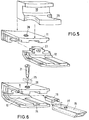
- the leakage protection segments are arranged on support arms which are attached to the outside of the rotary kiln jacket and distributed evenly over the circumference and project beyond the end of the rotary kiln jacket.
- the stress-free connection of the segment parts to one another and to the support arms enables the measure to be made from particularly heat-resistant and abrasion-resistant materials, for example from materials such as corundum or ceramic materials from the Group of hard materials, i.e. materials that normally show brittle behavior and are particularly sensitive to tensile stresses, which means that the service life can be increased considerably compared to normal metallic materials.
- the stress-free assembly of the segment parts into leakage protection segments also makes it possible to manufacture the segment parts from different materials depending on the expected load, since differences in material behavior, e.g. B. the coefficient of thermal expansion, not disadvantageous, for. B. in the form of tension.
- the segment parts are designed in accordance with the invention in such a way that, despite the tension-free assembly, there is a high level of mechanical cohesion with largely gas and dust-tight joints.
- Fig. 1 the furnace outlet area (9) of a rotary kiln (8) is shown schematically, which protrudes with its end edge (20) into the furnace head (7) of a cooler (6) downstream of the rotary kiln (8).
- the area of the furnace outlet which is shown in the following figures, is drawn with II in FIG. 1.
- the furnace outlet area (9) is designed as a double jacket, the inner wall of which is formed by the rotary kiln jacket (16) and the outer wall of which is formed by a tube (18).
- this double jacket is closed by leakage protection segments, which are formed from the outlet protection segment parts (11, 11 ', 12, 12') and which extend the rotary kiln (8) by the amount of its length.
- the leakage protection segment parts (11, 11 ', 12, 12') are designed and inserted into one another in such a way that only by securing by means of a bolt-shaped body, in the drawing figures this bolt-shaped body is a screw (21 ) is shown, a non-positive and largely dust and gas-tight connection is made in their joints.
- the leakage protection segment parts (11, 11 ', 12, 12') are also interlocked in the circumferential direction in order to provide gas and dust-tight joints between the leakage protection segment parts (11, 11 'and 12, 12 ').
- connection of the leakage protection segments with the rotary kiln jacket (16) is established via support arms (15).
- the support arms (15) which are hollow box-shaped in this embodiment, are fastened (for example welded) so that they over the end of the rotary kiln jacket (16).
- the leakage protection segments are pushed onto this protruding part of the support arms (15) with the aid of a molded body (19), one end of the molded body (19) into the correspondingly shaped recess (23) of the leakage protection segment part (12 or 12 ') and the other end of the shaped body (19) is inserted into the cavity of the support arm (15) which is in the form of a hollow box.
- the leakage protection segments are locked onto the support arms (15) in the exemplary embodiment shown with the aid of a screw (21) which passes from above through the recess (28) in the leakage protection segment part (11 or 11 ') and further through the recess (27) of the support arms (15) is performed.
- the screw (21) is held by a screw nut (25) which is arranged in a correspondingly designed groove in the leakage protection segment parts (12 or 12 ') and is prevented from rotating when the screw rotates.
- the leakage protection segment parts (10) are placed flush on top of the leakage protection segment parts (11 or 11 '), so that a common end edge (20) is formed with the leakage protection segment parts (11 or 11').
- This leakage protection segment part (10) is held by the refractory ramming compound (17), which adapts to the contours of the vertical part of this leakage protection segment part (10) and by anchors (22), which are welded onto the screws (21) and by which of the Dovetail-shaped horizontal parts of the leakage protection segment parts (10) formed recesses, which are filled with refractory ramming compound (17).
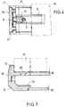
- FIG. 7 Another embodiment of leakage protection segments that is particularly suitable for the use of refractory stones (instead of refractory ramming paste) is shown in FIG. 7.
- the leakage protection segment parts (10 and 11 or 11 ') described in the exemplary embodiments in FIGS. 2 to 6 are combined to form a leakage protection segment part (13) with otherwise the same design of the other structural parts.
- the combination of the leakage protection segment parts (10 and 11 or 11 ') into one unit is necessary when using refractory bricks, since the anchors that are possible with refractory ramming compounds, for example the anchoring of the refractory lining with an anchor (22), are not in this form with bricks are possible or can only be carried out with considerable effort.
- the illustrated application examples only represent possible examples with regard to the design of the leakage protection segments with regard to the number and shape of the teeth, which can be replaced or supplemented by other types of teeth according to the invention.
- the number of leakage protection segment parts from which the leakage protection segments are formed can also differ from the number shown in the exemplary embodiments in accordance with the invention.
Landscapes
- Engineering & Computer Science (AREA)
- Mechanical Engineering (AREA)
- General Engineering & Computer Science (AREA)
- Muffle Furnaces And Rotary Kilns (AREA)
Abstract
Description
Die Erfindung ist auf einen Drehrohrofen zur Wärmebehandlung fließfähiger Materialien, insbesondere von Schüttgütern, mit einem Drehrohrofenmantel, der an seinem auslaufseitigen Ende als Doppelmantel ausgebildet ist, und mit Auslaufschutzsegmenten, die den Abschluß dieses Doppelmantels und die Auslaufkante des Drehrohrofens bilden, gerichtet.The invention is directed to a rotary kiln for the heat treatment of flowable materials, in particular bulk materials, with a rotary kiln jacket which is designed as a double jacket at its outlet end and with leakage protection segments which form the end of this double jacket and the outlet edge of the rotary kiln.
Das Auslaufende eines Drehrohrofens zur Wärmebehandlung fließfähiger Materialien, insbesondere von Schüttgütern, z. B. ein Drehrohrofen zur Produktion von Zementklinker, unterliegt im wesentlichen Beanspruchungen, die gleichzeitig und in unterschiedlichen Anteilen auftreten:
- □ thermische Beanspruchungen
- durch Kontakt mit dem hießen Produkt
- durch Kontakt mit der aus dem Kühler in den Ofen einströmenden Sekundärluft
- durch die Strahlung der Brennerflamme
- □ chemische Beanspruchungen
- durch Kontakt mit Produktbestandteilen
- durch Kontakt mit den im Gasstrom enthaltenden festen und gasförmigen Bestandteilen
- □ mechanische Beanspruchungen
- durch Oberflächenverschleiß infolge des über die Auslaufkante überlaufenden Produkts und durch vorbeiströmende feste Bestandteile des Gasstromes
- durch Verformungen des Drehrohrofenmantels
- □ thermal stress
- through contact with the product
- by contact with the secondary air flowing into the furnace from the cooler
- by the radiation of the burner flame
- □ chemical stress
- through contact with product components
- by contact with the solid and gaseous components contained in the gas stream
- □ mechanical stress
- by surface wear due to the product overflowing over the outlet edge and by solid components of the gas stream flowing past
- due to deformation of the rotary kiln shell
Aus der Praxis sind daher verschiedene Ausführungsformen des Auslaufendes von Drehrohröfen bekannt, wobei sich insbesondere bewährt hat, das Auslaufende in Form eines Doppelmantels auszubilden, dessen Stirnende durch Auslaufchutzsegmente abgeschlossen ist, während das entgegengesetzte Ende dieses Doppelmantels offen ist, so daß Kühlluft in den Hohlraum des Doppelmantels eingeblasen werden kann.Various embodiments of the outlet end of rotary kilns are therefore known in practice, and it has proven particularly useful to design the outlet end in the form of a double jacket, the front end of which is closed by outlet protection segments, while the opposite end of this double jacket is open, so that cooling air enters the cavity of the Double jacket can be blown.
So wird in der DE-A-31 46 320 ein Drehrohrofen beschrieben, dessen Auslaufende als Doppelmantel ausgebildet ist, dessen stirnseitige Abschlußsegmente durch in Trommelachsrichtung verlaufende Befestigungsschrauben gegen die Stirnseiten des Doppelmantels gezogen werden.DE-A-31 46 320 describes a rotary kiln, the outlet end of which is designed as a double jacket, the end segments of which are drawn against the front sides of the double jacket by fastening screws running in the direction of the drum axis.
Um den Außenring des Doppelmantels im wesentlichen konzentrisch um den Außenumfang des Ofenmantels zu halten, wird in der DE-A-30 11 012 vorgeschlagen, in den Zwischenraum zwischen dem Außenumfang des Ofenmantels und der Innenfläche des Außenrings eine Vielzahl flexibler Abstandsleisten anzuordnen. Die Abstandsleisten sind aus Stahl gefertigt und haben federähnliche Eigenschaften, so daß sie sich zur Aufnahme von unterschiedlichen Ausdehnungen infolge von unterschiedlichen Temperaturen des Drehrohrofenmantels und des Außenrings beim Betrieb des Drehrohrofens bewegen können.In order to keep the outer ring of the double jacket essentially concentric around the outer periphery of the furnace jacket, DE-A-30 11 012 proposes arranging a large number of flexible spacer strips in the space between the outer periphery of the furnace jacket and the inner surface of the outer ring. The spacer strips are made of steel and have spring-like properties, so that they can move to accommodate different expansions due to different temperatures of the rotary kiln jacket and the outer ring during operation of the rotary kiln.
In den letzten Jahren sind erhebliche Anstrengungen unternommen worden, die Wärmerückgewinnung in den den Drehrohröfen nachgeschalteten Kühlern zu steigern. Dies hat zu höheren Temperaturen der von den Kühlern in die Drehrohröfen strömende Sekundärluft geführt und damit zu einer höheren thermischen Beanspruchung des Auslaufbereichs, wodurch die Standzeiten der den Auslauf bildenden Materialien reduziert werden:
- Hitzebeständige Stahlgußwerkstoffe geraten an die Grenze ihrer Beanspruchbarkeit. Das Ausweichen auf höher zu beanspruchende metallische Werkstoffe erhöht drastisch die Anschaffungskosten.
- Die Luftkühlung läßt sich nicht in beliebiger Weise und den Erfordernissen entsprechend steigern.
- Heat-resistant cast steel materials reach the limits of their durability. Switching to more demanding metallic materials drastically increases the purchase costs.
- Air cooling cannot be increased in any way and according to requirements.
Es ist Aufgabe der Erfindung, die bekannten Ausführungsformen des Auslaufendes von Drehrohröfen weiterzubilden, und eine konstruktive und werkstofftechnische Lösung für die Gestaltung des Drehrohrofenauslaufs zu schaffen, die den gesteigerten Anforderungen gerecht wird und zu einer Standzeitverlängerung des Drehrohrofenauslaufs führt.It is an object of the invention to further develop the known embodiments of the outlet end of rotary kilns and to provide a constructive and material-related solution for the design of the rotary kiln outlet that meets the increased requirements and leads to an extension of the service life of the rotary kiln outlet.
Diese Aufgabe wird mit den Maßnahmen des Kennzeichnungsteils des Anspruchs 1 gelöst. Vorteilhafte Ausgestaltungen der Erfindung sind in den Unteransprüchen angegeben.This object is achieved with the measures of the characterizing part of
Gemäß der Erfindung wird der Drehrohrofenmantel durch Auslaufschutzsegmente an seinem auslaufseitigen Ende bis zu seiner Ablaufkante verlängert. Die Auslaufschutzsegmente sind hierzu auf Tragarme angeordnet, die gleichmäßig über den Umfang außen am Drehrohrofenmantel verteilt befestigt sind und über das Ende des Drehrohrofenmantels hinauskragen. Der Effekt dieser Konstruktion ist, daß bei Überhitzung im Bereich des Auslaufendes kein geschlossener Drehrohrofenmantel in diesem Bereich vorhanden ist, der trompetenförmig austrichtern kann, sondern ein aus Auslaufschutzsegmente gebildetes Drehrohrofenende, das weitgehend seine zylindrische Form beibehält.According to the invention, the rotary kiln jacket is extended by outlet protection segments at its outlet end to its drain edge. For this purpose, the leakage protection segments are arranged on support arms which are attached to the outside of the rotary kiln jacket and distributed evenly over the circumference and project beyond the end of the rotary kiln jacket. The effect of this construction is that in the event of overheating in the area of the outlet end, there is no closed rotary kiln jacket in this area that can funnel in a trumpet shape, but a rotary kiln end formed from leakage protection segments, which largely retains its cylindrical shape.
Durch das Merkmal der Erfindung, die Auslaufschutzsegmente mehrteilig auszuführen und die einzelnen Teile spannungsfrei miteinander und mit den Tragarmen lösbar in Form von Steckverbindungen zu verbinden, ergeben sich folgende weitere Vorteile:The feature of the invention of designing the leakage protection segments in several parts and releasably connecting the individual parts to one another and detachably with the support arms in the form of plug-in connections results in the following further advantages:
Zunächst ist es in einfacher Weise möglich, einzelne Segmentteile, die verschlissen oder sonstwie zerstört sind und deshalb durch neue Segmentteile ersetzt werden müssen, aus dem Auslaufschutzsegmenten herauszulösen, ohne das gesamte Segment ausbauen zu müssen. Weiterhin gestattet die spannungsfreie Verbindung der Segmentteile untereinander und mit den Tragarmen die Maßnahme, die Segmentteile aus besonders hitzebeständigen und abriebfesten Materialien zu fertigen, beispielsweise aus Materialien wie Korund oder keramische Materialien aus der Gruppe der Hartstoffe, also Werkstoffe, die normalerweise sprödes Verhalten zeigen und insbesondere gegenüber Zugspannungen empfindlich sind, wodurch die Standzeit gegenüber normale metallische Werkstoffe erheblich gesteigert werden kann.First of all, it is possible in a simple manner to remove individual segment parts that are worn or otherwise destroyed and therefore have to be replaced by new segment parts from the leakage protection segments without having to remove the entire segment. Furthermore, the stress-free connection of the segment parts to one another and to the support arms enables the measure to be made from particularly heat-resistant and abrasion-resistant materials, for example from materials such as corundum or ceramic materials from the Group of hard materials, i.e. materials that normally show brittle behavior and are particularly sensitive to tensile stresses, which means that the service life can be increased considerably compared to normal metallic materials.
Der spannungsfreie Zusammenbau der Segmentteile zu Auslaufschutzsegmenten gestattet es auch, die Segmentteile je nach der zu erwartenden Beanspruchung aus unterschiedlichen Werkstoffen zu fertigen, da Unterschiede im Werkstoffverhalten, z. B. des thermischen Ausdehnungskoeffizienten, sich nicht nachteilig, z. B. in Form von Verspannungen, auswirken kann. Die Segmentteile sind gemäß der Erfindung so gestaltet, daß trotz des spannungsfreien Zusammenbaus ein hoher mechanischer Zusammenhalt gegeben ist mit weitgehend gas- und staubdichten Trennfugen.The stress-free assembly of the segment parts into leakage protection segments also makes it possible to manufacture the segment parts from different materials depending on the expected load, since differences in material behavior, e.g. B. the coefficient of thermal expansion, not disadvantageous, for. B. in the form of tension. The segment parts are designed in accordance with the invention in such a way that, despite the tension-free assembly, there is a high level of mechanical cohesion with largely gas and dust-tight joints.
Weitere Vorteile, Einzelheiten und Merkmale der Erfindung werden für zwei Ausführungsbeispiele von möglichen Auslaufschutzsegmentteilen anhand von schematischen Zeichnungsfiguren näher erläutert.Further advantages, details and features of the invention are explained in more detail for two exemplary embodiments of possible leakage protection segment parts on the basis of schematic drawing figures.
Es zeigen:
- Fig. 1 :
- Seitenansicht des Drehrohrofenauslaufbereichs mit Doppelmantel eines Drehrohrofens;
- Fig. 2:
- ein Längsschnitt durch den aus Auslaufschutzsegmenten gebildeten Abschluß des Doppelmantels;
- Fig. 3:
- eine Ansicht entsprechend III-III der Fig. 2;
- Fig. 4:
- eine Draufsicht (geschnitten) entsprechen IV-IV der Fig. 2;
- Fig. 5:
- eine perspektivische Explosionszeichnung der Auslaufschutzsegmente entsprechend der Fig. 2;
- Fig. 6:
- eine perspektivische Explosionszeichnung der ineinandergeschobenen Auslaufschutzsegmente entsprechend Fig. 2;
- Fig. 7:
- einen Längsschnitt durch den aus Auslaufschutzsegmenten gebildeten Abschluß des Doppelmantels in einem weiteren möglichen Ausführungsbeispiel.
- Fig. 1:
- Side view of the rotary kiln outlet area with double jacket of a rotary kiln;
- Fig. 2:
- a longitudinal section through the end of the double jacket formed from leakage protection segments;
- Fig. 3:
- a view corresponding to III-III of Fig. 2;
- Fig. 4:
- a plan view (sectioned) corresponds to IV-IV of Fig. 2;
- Fig. 5:
- a perspective exploded view of the leakage protection segments corresponding to FIG. 2;
- Fig. 6:
- a perspective exploded view of the nested leakage protection segments corresponding to FIG. 2;
- Fig. 7:
- a longitudinal section through the end of the double jacket formed from leakage protection segments in a further possible embodiment.
In der Fig. 1 ist schematisch der Ofenauslaufbereich (9) eines Drehrohrofens (8) dargestellt, der mit seiner Abschlußkante (20) in den Ofenkopf (7) eines dem Drehrohrofen (8) nachgeschalteten Kühlers (6) hineinragt. Mit II ist in Fig. 1 der Bereich des Ofenauslaufs eingezeichnet, der in den nachfolgenden Figuren dargestellt ist.In Fig. 1 the furnace outlet area (9) of a rotary kiln (8) is shown schematically, which protrudes with its end edge (20) into the furnace head (7) of a cooler (6) downstream of the rotary kiln (8). The area of the furnace outlet, which is shown in the following figures, is drawn with II in FIG. 1.
Wie die Fig. 2 bis 6 zeigen, ist der Ofenauslaufbereich (9) als Doppelmantel ausgebildet, dessen innere Wandung vom Drehrohrofenmantel (16) und dessen äußere Wandung von einem Rohr (18) gebildet wird. Zum Auslaufende des Drehrohrofens hin wird dieser Doppelmantel von Auslaufschutzsegmenten abgeschlossen, die aus den Auslaufschutzsegmentteilen (11, 11', 12, 12') gebildet werden und die den Drehrohrofen (8) um den Betrag ihrer Länge nach verlängern.As shown in FIGS. 2 to 6, the furnace outlet area (9) is designed as a double jacket, the inner wall of which is formed by the rotary kiln jacket (16) and the outer wall of which is formed by a tube (18). At the outlet end of the rotary kiln, this double jacket is closed by leakage protection segments, which are formed from the outlet protection segment parts (11, 11 ', 12, 12') and which extend the rotary kiln (8) by the amount of its length.
Wie insbesondere die Fig. 3 bis 6 zeigen, sind die Auslaufschutzsegmentteile (11, 11', 12, 12') so gestaltet und so ineinandergesteckt, daß nur durch Sicherung mittels eines bolzenförmigen Körpers, in den Zeichnungsfiguren ist dieser bolzenförmige Körper als Schraube (21) dargestellt, eine kraftschlüssige und in ihren Trennfugen weitgehende staub- und gasdichte Verbindung untereinander hergestellt ist.As shown in FIGS. 3 to 6 in particular, the leakage protection segment parts (11, 11 ', 12, 12') are designed and inserted into one another in such a way that only by securing by means of a bolt-shaped body, in the drawing figures this bolt-shaped body is a screw (21 ) is shown, a non-positive and largely dust and gas-tight connection is made in their joints.
Wie in den Fig. 3 und 4 dargestellt ist, sind auch in Umfangsrichtung die Auslaufschutzsegmentteile (11, 11', 12, 12') miteinander verzahnt angeordnet, um gas- und staubdichte Trennfugen zwischen den Auslaufschutzsegmentteilen (11, 11' bzw. 12, 12') zu gewährleisten.As shown in FIGS. 3 and 4, the leakage protection segment parts (11, 11 ', 12, 12') are also interlocked in the circumferential direction in order to provide gas and dust-tight joints between the leakage protection segment parts (11, 11 'and 12, 12 ').
Die Verbindung der Auslaufschutzsegmente mit dem Drehrohrofenmantel (16) ist über Tragarme (15) hergestellt.The connection of the leakage protection segments with the rotary kiln jacket (16) is established via support arms (15).
Unterhalb des Drehrohrofenmantels (16), der mit Abstand von der Abschlußkante (20) des Drehrohrofens (8) endet, sind die Tragarme (15), die in diesem Ausführungsbeispiel hohlkastenförmig ausgebildet sind, so befestigt (beispielsweise angeschweißt), daß sie über das Ende des Drehrohrofenmantels (16) hinauskragen.Below the rotary kiln jacket (16), which ends at a distance from the end edge (20) of the rotary kiln (8), the support arms (15), which are hollow box-shaped in this embodiment, are fastened (for example welded) so that they over the end of the rotary kiln jacket (16).
Auf diesem überstehenden Teil der Tragarme (15) sind die Auslaufschutzsegmente mit Hilfe eines Formkörpers (19) aufgeschoben, wobei ein Ende des Formkörpers (19) in die entsprechend gestaltete Ausnehmung (23) des Auslaufschutzsegmentteils (12 bzw. 12') und das andere Ende des Formkörpers (19) in den Hohlraum des hohlkastenförmig ausgebildeten Tragarms (15) hineingesteckt ist.The leakage protection segments are pushed onto this protruding part of the support arms (15) with the aid of a molded body (19), one end of the molded body (19) into the correspondingly shaped recess (23) of the leakage protection segment part (12 or 12 ') and the other end of the shaped body (19) is inserted into the cavity of the support arm (15) which is in the form of a hollow box.
Die Arretierung der Auslaufschutzsegmente auf den Tragarmen (15) geschieht im dargestellten Ausführungsbeispiel mit Hilfe einer Schraube (21), die von oben durch die Ausnehmung (28) im Auslaufschutzsegmentteil (11 bzw. 11') und weiter durch die Ausnehmung (27) der Tragarme (15) geführt ist. Die Schraube (21) wird von einer Schraubenmutter (25) gehalten, die in einer entsprechend gestalteten Nut der Auslaufschutzsegmentteile (12 bzw. 12') angeordnet ist und auf diese Weise bei Drehung der Schraube an einer Drehung gehindert ist.The leakage protection segments are locked onto the support arms (15) in the exemplary embodiment shown with the aid of a screw (21) which passes from above through the recess (28) in the leakage protection segment part (11 or 11 ') and further through the recess (27) of the support arms (15) is performed. The screw (21) is held by a screw nut (25) which is arranged in a correspondingly designed groove in the leakage protection segment parts (12 or 12 ') and is prevented from rotating when the screw rotates.
Oben auf die Auslaufschutzsegmentteile (11 bzw. 11') sind die Auslaufschutzsegmentteile (10) bündig aufgesetzt, so daß mit den Auslaufschutzsegmentteilen (11 bzw. 11') eine gemeinsame Abschlußkante (20) gebildet wird. Gehalten wird dieses Auslaufschutzsegmentteil (10) durch die feuerfeste Stampfmasse (17), die sich den Konturen des vertikalen Teils dieses Auslaufschutzsegmentteils (10) anpaßt sowie durch Anker (22), die auf den Schrauben (21) angeschweißt sind und die durch die von den schwalbenschwanzförmigen horizontalen Teilen der Auslaufschutzsegmentteilen (10) gebildeten Ausnehmungen, die mit feuerfester Stampfmasse (17) gefüllt sind, hineinragen.The leakage protection segment parts (10) are placed flush on top of the leakage protection segment parts (11 or 11 '), so that a common end edge (20) is formed with the leakage protection segment parts (11 or 11'). This leakage protection segment part (10) is held by the refractory ramming compound (17), which adapts to the contours of the vertical part of this leakage protection segment part (10) and by anchors (22), which are welded onto the screws (21) and by which of the Dovetail-shaped horizontal parts of the leakage protection segment parts (10) formed recesses, which are filled with refractory ramming compound (17).
Eine weitere, besonders für die Verwendung von feuerfesten Steinen (anstelle von feuerfester Stampfmasse) geeignete Ausführungsform von Auslaufschutzsegmenten ist in der Fig. 7 dargestellt. In diesem Ausführungsbeispiel sind die in den Ausführungsbeispielen der Fig. 2 bis 6 beschriebenen Auslaufschutzsegmentteile (10 und 11 bzw. 11') zu einem Auslaufschutzsegmentteil (13) zusammengefaßt bei sonst gleicher Ausbildung der übrigen Konstruktionsteile. Die Zusammenfassung der Auslaufschutzsegmentteile (10 und 11 bzw. 11') zu einer Einheit ist bei Verwendung feuerfester Steine erforderlich, da die bei feuerfesten Stampfmassen möglichen Verankerungen, beispielsweise die Verankerung der feuerfesten Ausmauerung mittels eines Ankers (22), bei Steinen in dieser Form nicht möglich oder nur mit erheblichem Aufwand durchführbar sind.Another embodiment of leakage protection segments that is particularly suitable for the use of refractory stones (instead of refractory ramming paste) is shown in FIG. 7. In this exemplary embodiment, the leakage protection segment parts (10 and 11 or 11 ') described in the exemplary embodiments in FIGS. 2 to 6 are combined to form a leakage protection segment part (13) with otherwise the same design of the other structural parts. The combination of the leakage protection segment parts (10 and 11 or 11 ') into one unit is necessary when using refractory bricks, since the anchors that are possible with refractory ramming compounds, for example the anchoring of the refractory lining with an anchor (22), are not in this form with bricks are possible or can only be carried out with considerable effort.
Die dargestellten Anwendungsbeispiele stellen hinsichtlich der Gestaltung der Auslaufschutzsegmente bezüglich der Anzahl und der Form der Verzahnungen nur mögliche Beispiele dar, die entsprechend der Erfindung durch andere Verzahnungsformen ersetzt oder ergänzt werden können. Auch die Anzahl der Auslaufschutzsegmentteile, aus die die Auslaufschutzsegmente gebildet sind, können von der in den Ausführungsbeispielen gezeigten Anzahl entsprechend der Erfindung abweichen.The illustrated application examples only represent possible examples with regard to the design of the leakage protection segments with regard to the number and shape of the teeth, which can be replaced or supplemented by other types of teeth according to the invention. The number of leakage protection segment parts from which the leakage protection segments are formed can also differ from the number shown in the exemplary embodiments in accordance with the invention.
Claims (4)
Applications Claiming Priority (2)
| Application Number | Priority Date | Filing Date | Title |
|---|---|---|---|
| DE19934325303 DE4325303A1 (en) | 1993-07-28 | 1993-07-28 | Rotary tube furnace for the heat treatment of flowable materials |
| DE4325303 | 1993-07-28 |
Publications (2)
| Publication Number | Publication Date |
|---|---|
| EP0636847A1 true EP0636847A1 (en) | 1995-02-01 |
| EP0636847B1 EP0636847B1 (en) | 1999-03-24 |
Family
ID=6493907
Family Applications (1)
| Application Number | Title | Priority Date | Filing Date |
|---|---|---|---|
| EP19940109777 Expired - Lifetime EP0636847B1 (en) | 1993-07-28 | 1994-06-24 | Rotary drum furnace for the heat treatment of free flowing materials |
Country Status (3)
| Country | Link |
|---|---|
| EP (1) | EP0636847B1 (en) |
| DE (2) | DE4325303A1 (en) |
| DK (1) | DK0636847T3 (en) |
Cited By (2)
| Publication number | Priority date | Publication date | Assignee | Title |
|---|---|---|---|---|
| ES2144330A1 (en) * | 1996-04-24 | 2000-06-01 | Fundiciones Del Estanda S A | Furnace output segments for cement-making plants |
| CN101701765A (en) * | 2009-09-22 | 2010-05-05 | 洛阳新安电力集团炭素有限公司 | Method for improving and strengthening kiln head guard plate of rotary kiln |
Families Citing this family (2)
| Publication number | Priority date | Publication date | Assignee | Title |
|---|---|---|---|---|
| DE102004014872A1 (en) * | 2004-03-26 | 2005-10-13 | Khd Humboldt Wedag Ag | Outlet end of a rotary kiln |
| CN113074540B (en) * | 2020-09-18 | 2023-09-12 | 南京利卡维智能科技有限公司 | Multi-section ceramic furnace tube rapid assembling structure and material progressive method |
Citations (6)
| Publication number | Priority date | Publication date | Assignee | Title |
|---|---|---|---|---|
| US3016236A (en) * | 1960-06-22 | 1962-01-09 | Allis Chalmers Mfg Co | Rotary kiln discharge end construction |
| FR1559891A (en) * | 1967-02-21 | 1969-03-14 | ||
| DE2329061A1 (en) * | 1973-06-07 | 1975-01-02 | Kloeckner Humboldt Deutz Ag | Rotary kiln discharge ring is segmental - each segment divided into robust inner part and outer part |
| DE2852362A1 (en) * | 1977-12-05 | 1979-07-12 | Fives Cail Babcock | Protection for opening of rotating oven - uses multipart ring fixed to oven end air cooled hollow supports and concentric ring |
| EP0012660A1 (en) * | 1978-12-07 | 1980-06-25 | FIVES-CAIL BABCOCK, Société anonyme | Protection device for the discharge end of a rotary-drum furnace |
| US4212632A (en) * | 1979-05-02 | 1980-07-15 | Allis-Chalmers Corporation | Cooling arrangement for rotary kiln |
Family Cites Families (4)
| Publication number | Priority date | Publication date | Assignee | Title |
|---|---|---|---|---|
| DE900671C (en) * | 1951-01-27 | 1953-12-28 | Miag Vertriebs Gmbh | Cooled outlet for rotary furnaces |
| DE2160300C3 (en) * | 1971-12-04 | 1975-05-07 | Kloeckner-Humboldt-Deutz Ag, 5000 Koeln | Spacers between the jackets of a double-walled pipe or container exposed to temperature differences |
| DE3146320A1 (en) * | 1981-11-23 | 1983-08-04 | Krupp Polysius Ag, 4720 Beckum | Rotary drum for hot material |
| SU1408179A1 (en) * | 1986-07-30 | 1988-07-07 | Карагандинский металлургический комбинат | Unloading end of rotary furnace |
-
1993
- 1993-07-28 DE DE19934325303 patent/DE4325303A1/en not_active Withdrawn
-
1994
- 1994-06-24 DE DE59407992T patent/DE59407992D1/en not_active Expired - Lifetime
- 1994-06-24 EP EP19940109777 patent/EP0636847B1/en not_active Expired - Lifetime
- 1994-06-24 DK DK94109777T patent/DK0636847T3/en active
Patent Citations (6)
| Publication number | Priority date | Publication date | Assignee | Title |
|---|---|---|---|---|
| US3016236A (en) * | 1960-06-22 | 1962-01-09 | Allis Chalmers Mfg Co | Rotary kiln discharge end construction |
| FR1559891A (en) * | 1967-02-21 | 1969-03-14 | ||
| DE2329061A1 (en) * | 1973-06-07 | 1975-01-02 | Kloeckner Humboldt Deutz Ag | Rotary kiln discharge ring is segmental - each segment divided into robust inner part and outer part |
| DE2852362A1 (en) * | 1977-12-05 | 1979-07-12 | Fives Cail Babcock | Protection for opening of rotating oven - uses multipart ring fixed to oven end air cooled hollow supports and concentric ring |
| EP0012660A1 (en) * | 1978-12-07 | 1980-06-25 | FIVES-CAIL BABCOCK, Société anonyme | Protection device for the discharge end of a rotary-drum furnace |
| US4212632A (en) * | 1979-05-02 | 1980-07-15 | Allis-Chalmers Corporation | Cooling arrangement for rotary kiln |
Cited By (3)
| Publication number | Priority date | Publication date | Assignee | Title |
|---|---|---|---|---|
| ES2144330A1 (en) * | 1996-04-24 | 2000-06-01 | Fundiciones Del Estanda S A | Furnace output segments for cement-making plants |
| CN101701765A (en) * | 2009-09-22 | 2010-05-05 | 洛阳新安电力集团炭素有限公司 | Method for improving and strengthening kiln head guard plate of rotary kiln |
| CN101701765B (en) * | 2009-09-22 | 2012-12-26 | 洛阳新安电力集团炭素有限公司 | Method for improving and strengthening kiln head guard plate of rotary kiln |
Also Published As
| Publication number | Publication date |
|---|---|
| DE4325303A1 (en) | 1995-02-02 |
| DE59407992D1 (en) | 1999-04-29 |
| DK0636847T3 (en) | 2000-06-05 |
| EP0636847B1 (en) | 1999-03-24 |
Similar Documents
| Publication | Publication Date | Title |
|---|---|---|
| DE3228902C2 (en) | ||
| EP1741981A1 (en) | Ceramic heatshield element and high temperature gas reactor lined with such a heatshield | |
| DE2459180B2 (en) | COMPENSATOR CONNECTION FOR HOT MEDIA, IN PARTICULAR FOR THE HOT WIND NOZZLE IN A BURST FURNACE | |
| EP2175219B1 (en) | Fire-proof cladding element | |
| DE4420450C2 (en) | Coolable delivery for a high-temperature gasification reactor | |
| EP0636847A1 (en) | Rotary drum furnace for the heat treatment of free flowing materials | |
| EP0440899A1 (en) | Refractory nozzle | |
| EP3177743B1 (en) | Burner-lance unit | |
| EP1602889B1 (en) | Industrial furnace | |
| DE2703064A1 (en) | Expansion bellows pipe coupling - has bending loads absorbed by protective external bellow housing | |
| DE900671C (en) | Cooled outlet for rotary furnaces | |
| DE2329061A1 (en) | Rotary kiln discharge ring is segmental - each segment divided into robust inner part and outer part | |
| WO2005090620A1 (en) | Rotary drum-type kiln comprising fireproof stirring bodies for remelting aluminium | |
| DE602004004645T2 (en) | Elongated stopper rod | |
| DE1442759C3 (en) | Pipe connection between a tubular part made of metal and a tubular part made of heat-resistant material | |
| DE102010015842A1 (en) | Hot blast nozzle stick for a shaft furnace, in particular blast furnace | |
| DE3639001C1 (en) | Seal of a ceramic pipe | |
| EP0091422B1 (en) | Shaft furnace tuyere connection | |
| DE2702876B2 (en) | Rotary kiln with a number of planetary cooling tubes | |
| DE2803297B1 (en) | Wall duct for the connecting pipes of blast furnace radiators | |
| AT270708B (en) | Multi-part nozzle assembly for shaft furnaces, especially for blast furnaces | |
| DD150907A5 (en) | GAS GENERATOR FOR FINE-COAL CARBON FUELS | |
| DE102008046992A1 (en) | Tilting, rotary drum-type furnace for melting of e.g. aluminum, has drum with drum body, where flexible rotating body is provided in inner space at front side of drum and extends from front side of drum in axial direction | |
| AT215454B (en) | Immersion tube for the vacuum degassing of molten metal, especially molten steel | |
| WO2024056721A1 (en) | Seal for a rotary kiln |
Legal Events
| Date | Code | Title | Description |
|---|---|---|---|
| PUAI | Public reference made under article 153(3) epc to a published international application that has entered the european phase |
Free format text: ORIGINAL CODE: 0009012 |
|
| 17P | Request for examination filed |
Effective date: 19940906 |
|
| AK | Designated contracting states |
Kind code of ref document: A1 Designated state(s): DE DK FR IT |
|
| 17Q | First examination report despatched |
Effective date: 19970219 |
|
| RAP1 | Party data changed (applicant data changed or rights of an application transferred) |
Owner name: DEUTZ AKTIENGESELLSCHAFT |
|
| GRAG | Despatch of communication of intention to grant |
Free format text: ORIGINAL CODE: EPIDOS AGRA |
|
| GRAG | Despatch of communication of intention to grant |
Free format text: ORIGINAL CODE: EPIDOS AGRA |
|
| GRAH | Despatch of communication of intention to grant a patent |
Free format text: ORIGINAL CODE: EPIDOS IGRA |
|
| GRAH | Despatch of communication of intention to grant a patent |
Free format text: ORIGINAL CODE: EPIDOS IGRA |
|
| GRAA | (expected) grant |
Free format text: ORIGINAL CODE: 0009210 |
|
| AK | Designated contracting states |
Kind code of ref document: B1 Designated state(s): DE DK FR IT |
|
| PG25 | Lapsed in a contracting state [announced via postgrant information from national office to epo] |
Ref country code: IT Free format text: LAPSE BECAUSE OF FAILURE TO SUBMIT A TRANSLATION OF THE DESCRIPTION OR TO PAY THE FEE WITHIN THE PRE;WARNING: LAPSES OF ITALIAN PATENTS WITH EFFECTIVE DATE BEFORE 2007 MAY HAVE OCCURRED AT ANY TIME BEFORE 2007. THE CORRECT EFFECTIVE DATE MAY BE DIFFERENT FROM THE ONE RECORDED.SCRIBED TIME-LIMIT Effective date: 19990324 |
|
| REF | Corresponds to: |
Ref document number: 59407992 Country of ref document: DE Date of ref document: 19990429 |
|
| ET | Fr: translation filed | ||
| PLBE | No opposition filed within time limit |
Free format text: ORIGINAL CODE: 0009261 |
|
| STAA | Information on the status of an ep patent application or granted ep patent |
Free format text: STATUS: NO OPPOSITION FILED WITHIN TIME LIMIT |
|
| 26N | No opposition filed | ||
| REG | Reference to a national code |
Ref country code: DK Ref legal event code: T3 |
|
| PGFP | Annual fee paid to national office [announced via postgrant information from national office to epo] |
Ref country code: DK Payment date: 20120620 Year of fee payment: 19 Ref country code: DE Payment date: 20120616 Year of fee payment: 19 |
|
| PGFP | Annual fee paid to national office [announced via postgrant information from national office to epo] |
Ref country code: FR Payment date: 20120705 Year of fee payment: 19 |
|
| REG | Reference to a national code |
Ref country code: DK Ref legal event code: EBP Effective date: 20130630 |
|
| REG | Reference to a national code |
Ref country code: FR Ref legal event code: ST Effective date: 20140228 |
|
| REG | Reference to a national code |
Ref country code: DE Ref legal event code: R119 Ref document number: 59407992 Country of ref document: DE Effective date: 20140101 |
|
| PG25 | Lapsed in a contracting state [announced via postgrant information from national office to epo] |
Ref country code: DE Free format text: LAPSE BECAUSE OF NON-PAYMENT OF DUE FEES Effective date: 20140101 |
|
| PG25 | Lapsed in a contracting state [announced via postgrant information from national office to epo] |
Ref country code: FR Free format text: LAPSE BECAUSE OF NON-PAYMENT OF DUE FEES Effective date: 20130701 |
|
| PG25 | Lapsed in a contracting state [announced via postgrant information from national office to epo] |
Ref country code: DK Free format text: LAPSE BECAUSE OF NON-PAYMENT OF DUE FEES Effective date: 20130630 |