EP0636732B1 - Washing machine equipped for drying - Google Patents
Washing machine equipped for drying Download PDFInfo
- Publication number
- EP0636732B1 EP0636732B1 EP94111073A EP94111073A EP0636732B1 EP 0636732 B1 EP0636732 B1 EP 0636732B1 EP 94111073 A EP94111073 A EP 94111073A EP 94111073 A EP94111073 A EP 94111073A EP 0636732 B1 EP0636732 B1 EP 0636732B1
- Authority
- EP
- European Patent Office
- Prior art keywords
- cooling water
- washing machine
- water
- hollow body
- inlet
- Prior art date
- Legal status (The legal status is an assumption and is not a legal conclusion. Google has not performed a legal analysis and makes no representation as to the accuracy of the status listed.)
- Expired - Lifetime
Links
Images
Classifications
-
- D—TEXTILES; PAPER
- D06—TREATMENT OF TEXTILES OR THE LIKE; LAUNDERING; FLEXIBLE MATERIALS NOT OTHERWISE PROVIDED FOR
- D06F—LAUNDERING, DRYING, IRONING, PRESSING OR FOLDING TEXTILE ARTICLES
- D06F58/00—Domestic laundry dryers
- D06F58/20—General details of domestic laundry dryers
- D06F58/24—Condensing arrangements
-
- D—TEXTILES; PAPER
- D06—TREATMENT OF TEXTILES OR THE LIKE; LAUNDERING; FLEXIBLE MATERIALS NOT OTHERWISE PROVIDED FOR
- D06F—LAUNDERING, DRYING, IRONING, PRESSING OR FOLDING TEXTILE ARTICLES
- D06F25/00—Washing machines with receptacles, e.g. perforated, having a rotary movement, e.g. oscillatory movement, the receptacle serving both for washing and for centrifugally separating water from the laundry and having further drying means, e.g. using hot air
-
- D—TEXTILES; PAPER
- D06—TREATMENT OF TEXTILES OR THE LIKE; LAUNDERING; FLEXIBLE MATERIALS NOT OTHERWISE PROVIDED FOR
- D06F—LAUNDERING, DRYING, IRONING, PRESSING OR FOLDING TEXTILE ARTICLES
- D06F58/00—Domestic laundry dryers
- D06F58/20—General details of domestic laundry dryers
- D06F58/22—Lint collecting arrangements
Definitions
- the invention relates to a washing machine set up for drying with a condenser which consists of a hollow body through which moist process air can flow from bottom to top and which is flushed with tap water for cooling purposes via a switchable valve in the inlet.
- Such a so-called washer dryer is known from German Offenlegungsschrift 41 04 760.
- a condenser arranged therein it has proven to be a problem that laundry fluff carried along in the process air during the drying section in particular can settle on the inner wall of the condenser and can dry out after the end of the drying section. This danger is particularly favored by limiting the flow of the cooling water to the smallest possible value in order to save fresh cooling water.
- the invention has for its object to improve the washing machine described above so that the lint settling in the condenser can be rinsed out again.
- the amount of water required for the condensation process should be kept as small as possible, whereas a large stream of water is required to rinse out the fluff. Both functions are to be implemented with just one inlet valve.
- this object is achieved in that the inflow is dimensioned for a water flow which is suitable for flushing the fluff of the hollow body and can be operated intermittently for supplying cooling water.
- a lint rinsing section can be inserted at suitable times during the washing and / or drying process, for which only a suitably long switch-on phase of the feed valve is required.
- the invention is further developed in that the inlet is aimed at a baffle plate which distributes the rinsing or cooling water in a bell shape on all sides.
- a uniform flushing of the inner walls of the hollow condenser body can be achieved, so that during the lint rinsing section, the strong flow of the cooling water reaches all surface sections of the condenser on which lint may have settled.
- the bell-shaped distribution causes a largely intensive contact of the cooling water with the process air flow, so that the lint entrained by the process air does not reach the blower.
- a further improvement of the washing machine set up according to the invention can be achieved in that projections projecting into the process air flow are arranged in the lower region of the hollow body and lead cooling water flowing down the walls into the air flow. As a result, large portions of the cooling water are directed directly into the air flow, which comes into more intensive contact with the cooling water. This measure increases the chance of being able to wash out almost all of the fluff carried in the process air stream. It also has a positive effect on the condensation effect.
- a storage space for the cooling water is arranged in the upper region of the hollow body in the outflow region of the inlet, said storage space being provided with outflow openings which allow the delayed outflow of the cooling water.
- the storage space arrangement is advantageously made such that its drainage openings are directed into the process air stream. As a result, the intimate contact between the process air stream and the cooling water can be intensified.
- the hollow condenser body 1 is shaped in accordance with the free spaces remaining in the washing machine and the flow of moist process air flows from the supply air opening 2 arranged at the bottom to the fan connection opening 3 arranged at the top, essentially from bottom to top. This is indicated by the large, hollow arrows.
- the supply air opening 2 arranged at the bottom is connected in a manner not shown to a tub of the washing machine and also serves as a drain opening for rinsing or cooling water supplied from above and used as such in the hollow body. It is pumped out of the tub in the usual way by a tub pump.
- the inlet 4 contains a solenoid valve, not shown, and opens onto a baffle plate 5, which distributes the incoming water in a bell shape in the cavity of the condenser. It flows down the inner walls of the hollow body 1 to the inlet and outlet openings 2 and is partially caught by a protrusion protruding into the process air stream.
- the projection consists of a distributor plate 6 which contains flow openings 7 for the process air. As a result, the cooling water is additionally brought into intensive contact with the process air flow. On the way up, the process air can touch several such projections in a manner not shown here, which force the process air into a meandering path, for example.
- the cooling water is fed intermittently through the inlet 4. So that the interior of the condenser does not dry out during the feed pauses, as a result of which neither condensation nor lint washing would take place, a storage space 8 is arranged in the upper part in the inflow area of the water supply 4, the baffle wall 9 having drain openings 10.
- the size of the drainage openings is such that they allow the delayed drainage of the pent-up cooling water at a time which corresponds approximately to the pause in the water supply.
- the drain openings 10 can be arranged as in the example shown on the sides of the baffle 9 or only on the lower side or in the form of holes.
- the storage space 8 can, in contrast to the case shown here, be arranged in a ring or U-shape around the cross section of the hollow body and direct its drainage openings into the process air flow from three or four sides. Decisive for the design of the hollow body and the storage space are essentially the local conditions in a washing machine in which this capacitor is to be arranged.
- the fresh water inlet with its valve, not shown here, is designed for a large water flow rate for flushing out the fluff. Since only a small amount of water flow is required for condensing, the valve for the condensation process can be switched on in cycles.
- the baffle plate 5 under the water inlet forces part of the fresh water to run down the walls. It also rinses the walls free of fluff during the condensation process. Due to the intensive swirling of part of the cooling water at the projections 6, fluff is washed out of the process air particularly effectively and the condensation effect is improved. In the intervals between the water supply, the water supply in the Storage space 8, the washing of the inner walls of the hollow body 1 and the feeding of the projections 6 for the purpose of swirling the cooling water.
- the hollow body of the condenser is generally designed in such a way that the water runs at least partially down all walls from the highest point via a baffle plate.
- the water accumulating during the lint rinsing process and flowing out through the supply air opening 2 into the tub of the washing machine is expediently pumped out by the drain pump so that no lint can get to the laundry. These fluff are then removed at the same time as the water to be pumped out.
- condenser flushings are advantageously carried out when there is a low water level in the tub which does not reach the supply air opening 2 of the condenser.
- the blower and the pump can be run while the fresh water is being supplied intermittently.
- the upper part of the hollow condenser body is freed from fluff by directly washing the walls and the vertical part of the hollow body by swirling the water. With regular automatic use during the washing process, a small amount of water is sufficient to flush the fluff.
- the measures according to the invention only require an inlet valve and a hose to the condenser inlet 4. Also, no further components are required for a second valve, since the water flow rates can be controlled by switching the valve on for different lengths or in cycles.
Description
Die Erfindung betrifft eine zum Trocknen eingerichtete Waschmaschine mit einem Kondensator, der aus einem im wesentlichen von unten nach oben mit feuchter Prozeßluft durchströmbaren Hohlkörper besteht und zu Kühlzwecken über ein schaltbares Ventil im Zulauf mit Leitungswasser bespült wird.The invention relates to a washing machine set up for drying with a condenser which consists of a hollow body through which moist process air can flow from bottom to top and which is flushed with tap water for cooling purposes via a switchable valve in the inlet.
Ein solcher sogenannter Waschtrockner ist aus der deutschen Offenlegungsschrift 41 04 760 bekannt. In einem darin angeordneten Kondensator hat sich als Problem erwiesen, daß vor allem während des Trocknungsabschnittes in der Prozeßluft mitgetragene Wäscheflusen sich an der Innenwandung des Kondensators absetzen und nach Ende des Trocknungsabschnitts antrocknen können. Diese Gefahr wird insb. dadurch begünstigt, daß man aus Gründen der Ersparnis von frischem Kühlwasser den Durchfluß des Kühlwassers auf einem möglichst kleinen Wert begrenzt. Durch geeignete, konstruktive Maßnahmen innerhalb des Kondensator-Hohlkörpers wird zwar eine möglichst breitflächige Verteilung des Kühlwassers angestrebt, jedoch werden dadurch nicht alle Wandbereiche gleichmäßig benetzt, an denen sich dann noch Flusen absetzen, und außerdem strömen noch erhebliche Flusenanteile mit der Prozeßluft durch den Kondensator bis ins Gebläse, in dem sich die Flusen dann schließlich absetzen.Such a so-called washer dryer is known from German Offenlegungsschrift 41 04 760. In a condenser arranged therein, it has proven to be a problem that laundry fluff carried along in the process air during the drying section in particular can settle on the inner wall of the condenser and can dry out after the end of the drying section. This danger is particularly favored by limiting the flow of the cooling water to the smallest possible value in order to save fresh cooling water. Appropriate, constructive measures within the hollow condenser body aim to distribute the cooling water as widely as possible, but this does not uniformly wet all the wall areas on which fluff is still deposited, and also cause considerable flow Lint portions with the process air through the condenser into the blower, in which the lint then finally settles.
Aus der EP-A-0 340 403 ist eine ähnliche Vorrichtung mit einem Hohlkörper bekannt, der zwei separate Zulaüfe für die Kühlwasserzufuhr und Flusenspülung aufweist, wobei die Flusenspülung intermittierend betrieben werden kann.From EP-A-0 340 403 a similar device with a hollow body is known which has two separate inlets for the cooling water supply and lint rinsing, the lint rinsing being able to be operated intermittently.
Der Erfindung liegt die Aufgabe zugrunde, die eingangs beschriebene Waschmaschine so zu verbessern, daß die im Kondensator sich absetzenden Flusen wieder ausgespült werden können. Dabei soll die für den Kondensationsprozeß benötigte Wassermenge so klein wie möglich gehalten werden, wohingegen zum Ausspülen der Flusen ein großer Wasserstrom erforderlich ist. Beide Funktionen sollen mit nur einem Zulaufventil realisiert werden.The invention has for its object to improve the washing machine described above so that the lint settling in the condenser can be rinsed out again. The amount of water required for the condensation process should be kept as small as possible, whereas a large stream of water is required to rinse out the fluff. Both functions are to be implemented with just one inlet valve.
Erfindungsgemäß wird diese Aufgabe dadurch gelöst, daß der Zulauf für einen Wasserstrom bemessen, der zum Flusenspülen des Hohlkörpers geeignet ist, und zum Zuführen von Kühlwasser intermittierend betreibbar ist. Dadurch kann zu geeigneten Zeitpunkten während des Wasch- und/oder Trocknungsprozesses ein Flusenspül-Abschnitt eingefügt werden, für den lediglich eine geeignet lange Einschaltphase des Zulaufventils vonnöten ist.According to the invention, this object is achieved in that the inflow is dimensioned for a water flow which is suitable for flushing the fluff of the hollow body and can be operated intermittently for supplying cooling water. As a result, a lint rinsing section can be inserted at suitable times during the washing and / or drying process, for which only a suitably long switch-on phase of the feed valve is required.
In besonders vorteilhafter Weise wird die Erfindung dadurch weitergebildet, daß der Zulauf auf eine Prallplatte zielt, die das Spül- bzw. Kühlwasser glockenförmig nach allen Seiten verteilt. Hierdurch kann eine gleichmäßige Bespülung der Innenwände des Kondensator-Hohlkörpers erreicht werden, so daß während des Flusenspül-Abschnitts der starke Strom des Kühlwassers alle Flächenabschnitte des Kondensators erreicht, an denen sich evtl. Flusen abgesetzt haben könnten. Außerdem bewirkt die glockenförmige Verteilung einen weitgehend intensiven Kontakt des Kühlwassers mit dem Prozeßluftstrom, so daß die von der Prozeßluft mitgerissenen Flusen nicht zum Gebläse gelangen.In a particularly advantageous manner, the invention is further developed in that the inlet is aimed at a baffle plate which distributes the rinsing or cooling water in a bell shape on all sides. As a result, a uniform flushing of the inner walls of the hollow condenser body can be achieved, so that during the lint rinsing section, the strong flow of the cooling water reaches all surface sections of the condenser on which lint may have settled. In addition, the bell-shaped distribution causes a largely intensive contact of the cooling water with the process air flow, so that the lint entrained by the process air does not reach the blower.
Eine weitere Verbesserung der erfindungsgemäß eingerichteten Waschmaschine ist dadurch erzielbar, daß im unteren Bereich des Hohlkörpers in den Prozeßluft-Strom ragende Vorsprünge angeordnet sind, die an den Wänden herabfließendes Kühlwasser in den Luftstrom führen. Hierdurch werden große Anteile des Kühlwassers unmittelbar in den Luftstrom geleitet, der intensiver mit dem Kühlwasser in Berührung kommt. Diese Maßnahme erhöht die Chance, annähernd alle im Prozeßluft-Strom mitgeführten Flusen auswaschen zu können. Außerdem wird der densationseffekt damit positiv beeinflußt.A further improvement of the washing machine set up according to the invention can be achieved in that projections projecting into the process air flow are arranged in the lower region of the hollow body and lead cooling water flowing down the walls into the air flow. As a result, large portions of the cooling water are directed directly into the air flow, which comes into more intensive contact with the cooling water. This measure increases the chance of being able to wash out almost all of the fluff carried in the process air stream. It also has a positive effect on the condensation effect.
In einem weiteren, vorteilhaften Ausführungsbeispiel der Erfindung ist im oberen Bereich des Hohlkörpers im Abflußbereich des Zulaufs ein Stauraum für das Kühlwasser angeordnet, der mit den verzögerten Ablauf aufgestauten Kühlwassers gestattenden Abflußöffnungen versehen ist. Hierdurch kann auf einfache Weise erreicht werden, daß beim intermittierenden Zuführen von Kühlwasser während des Kondensationsprozesses das Kühlwasser trotzdem gleichmäßig an den Innenwänden des Kondensator-Hohlkörpers herabfließt und damit Flusen-Auswaschungs-Pausen vermeidet, die etwa dadurch entstünden, daß in den Wasser-Zuführungs-Pausen der Hohlkörper austrocknet.In a further advantageous embodiment of the invention, a storage space for the cooling water is arranged in the upper region of the hollow body in the outflow region of the inlet, said storage space being provided with outflow openings which allow the delayed outflow of the cooling water. This can be achieved in a simple manner that when cooling water is intermittently supplied during the condensation process, the cooling water still flows down uniformly on the inner walls of the hollow condenser body and thus avoids lint-washing pauses, which would result, for example, from the fact that in the water supply Breaks the hollow body dry out.
Vorteilhafterweise wird die Stauraumanordnung so getroffen, daß seine Abflußöffnungen in den Prozeßluft-Strom gerichtet sind. Dadurch ist der innige Kontakt zwischen dem Prozeßluft-Strom und dem Kühlwasser intensivierbar.The storage space arrangement is advantageously made such that its drainage openings are directed into the process air stream. As a result, the intimate contact between the process air stream and the cooling water can be intensified.
Anhand eines in der Zeichnung dargestellten Ausführungsbeispieles ist die Erfindung nachstehend erläutert. Es zeigen
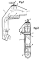
- Fig. 1
- die Seitenansicht und
- Fig. 2
- die Rückansicht eines erfindungsgemäß statteten, durchsichtigen Kondensator-Hohlkörpers.
- Fig. 1
- the side view and
- Fig. 2
- the rear view of a transparent capacitor hollow body equipped according to the invention.
Der Kondensator-Hohlkörper 1 ist entsprechend den in der Waschmaschine verbliebenen Freiräumen geformt und wird von der unten angeordneten Zuluftöffnung 2 bis zur oben angeordneten Gebläse-Anschlußöffnung 3 im wesentlichen von unten nach oben mit feuchter Prozeßluft durchströmt. Dies ist durch die hohl gezeichneten großen Pfeile angedeutet. Die unten angeordnete Zuluftöffnung 2 ist in nicht dargestellter Weise an einen Laugenbehälter der Waschmaschine angeschlossen und dient gleichfalls als Abflußöffnung für von oben zugeführtes und im Hohlkörper als solches verbrauchtes Spül- bzw. Kühlwasser. Aus dem Laugenbehälter wird es in üblicher Weise durch eine Laugenpumpe abgepumpt.The
Der Zulauf 4 enthält ein nicht dargestelltes Magnetventil und mündet auf eine Prallplatte 5, die das zulaufende Wasser glockenförmig im Hohlraum des Kondensators verteilt. Es fließt an den Innenwänden des Hohlkörpers 1 zur Zuluft- und Abflußöffnung 2 herab und wird teilweise von einem in den Prozeßluft-Strom ragenden Vorsprung aufgefangen. Der Vorsprung besteht aus einer Verteilerplatte 6, die für die Prozeßluft Durchströmungsöffnungen 7 enthält. Hierdurch wird das Kühlwasser zusätzlich intensiv mit dem Prozeß-Luftstrom in Berührung gebracht. Auf dem Weg nach oben kann die Prozeß-Luft in hier nicht dargestellter Weise mehrere derartige Vorsprünge berühren, die die Prozeßluft beispielsweise in einen Mäanderweg zwingen.The inlet 4 contains a solenoid valve, not shown, and opens onto a
Zum normalen Kondensieren der Prozeßluft-Feuchtigkeit wird das Kühlwasser über den Zulauf 4 intermittierend zugeführt. Damit in den Zuführungspausen der Innenraum des Kondensators nicht austrocknet, wodurch weder eine Kondensation noch ein Flusenauswaschen stattfinden würde, ist im oberen Teil im Zulaufbereich der Wasserzuführung 4 ein Stauraum 8 angeordnet, dessen Stauwand 9 Abflußöffnungen 10 aufweist. Die Abflußöffnungen sind in ihrer Größe so bemessen, daß sie den verzögerten Ablauf des aufgestauten Kühlwassers in einer Zeit gestatten, die etwa der Wasserzuführungs-Pause entspricht. Dabei können die Abflußöffnungen 10 wie im dargestellten Beispiel an den Seiten der Stauwand 9 oder nur an der unteren Seite oder in Form von Löchern angeordnet ein. Der Stauraum 8 kann auch, anders als hier dargestellt, ringförmig oder U-förmig um den Querschnitt des Hohlkörpers herum angeordnet sein und seine Abflußöffnungen von drei oder vier Seiten aus in den Prozeßluft-Strom richten. Maßgebend für die Gestaltung des Hohlkörpers und des Stauraumes sind im wesentlichen die örtlichen Gegebenheiten in einer Waschmaschine, in der dieser Kondensator angeordnet sein soll.For normal condensation of the process air humidity, the cooling water is fed intermittently through the inlet 4. So that the interior of the condenser does not dry out during the feed pauses, as a result of which neither condensation nor lint washing would take place, a
Der Frischwasserzulauf mit seinem hier nicht dargestellten Ventil ist auf eine große Wasserdurchlaufmenge zum Ausspülen der Flusen ausgelegt. Da zum Kondensieren nur eine kleinere Wasserdurchlaufmenge benötigt wird, kann das Ventil für den Kondensationsprozeß taktweise eingeschaltet werden. Die Prallplatte 5 unter dem Wasserzulauf zwingt einen Teil des Frischwassers, an den Wänden herabzulaufen. Es spült die Wände auch während des Kondensationsprozesses von Flusen frei. Durch die intensive Verwirbelung eines Teils des Kühlwassers an den Vorsprüngen 6 werden Flusen besonders wirksam aus der Prozeßluft ausgewaschen und der Kondensationseffekt verbessert. In den Taktpausen der Wasserzufuhr übernimmt der Wasservorrat im Stauraum 8 die Bespülung der Innenwände des Hohlkörpers 1 und die Speisung der Vorsprünge 6 zwecks Verwirbelung des Kühlwassers.The fresh water inlet with its valve, not shown here, is designed for a large water flow rate for flushing out the fluff. Since only a small amount of water flow is required for condensing, the valve for the condensation process can be switched on in cycles. The
Der Hohlkörper des Kondensators ist im allgemeinen so ausgebildet, daß das Wasser von der höchsten Stelle über eine Prallplatte wenigstens teilweise an allen Wänden herunter läuft. Zweckmäßigerweise wird das während des Flusenspülvorganges anfallende und durch die Zuluftöffnung 2 in den Laugenbehälter der Waschmaschine abfließende Wasser sofort mittels der Laugenpumpe abgepumpt, damit keine Flusen an die Wäsche gelangen können. Diese Flusen werden dann gleichzeitig mit dem abzupumpenden Wasser entfernt.The hollow body of the condenser is generally designed in such a way that the water runs at least partially down all walls from the highest point via a baffle plate. The water accumulating during the lint rinsing process and flowing out through the supply air opening 2 into the tub of the washing machine is expediently pumped out by the drain pump so that no lint can get to the laundry. These fluff are then removed at the same time as the water to be pumped out.
Da auch beim Waschen Flusen aus der Wäsche gelöst werden, die vom Waschmittelschaum in den Kondensator getragen werden, ist es zweckmäßig, während des Waschabschnitts in Abständen Kondensatorspülungen vorzunehmen. Vorteilhafterweise sind diese Kondensatorspülungen dann vorzunehmen, wenn im Laugenbehälter ein niedriger Wasserstand vorhanden ist, der nicht an die Zuluftöffnung 2 des Kondensators heranreicht. Vorteilhafterweise kann man während der taktweisen Zuführung von Frischwasser das Gebläse und die Pumpe laufen lassen. Dadurch wird der obere Teil des Kondensator-Hohlkörpers durch direktes Bespülen der Wände und der senkrechte Teil des Hohlkörpers durch Verwirbelung des Wassers von Flusen befreit. Bei regelmäßiger automatischer Anwendung während des Waschprozesses genügt zum Flusenspülen eine jeweils geringe Wassermenge.Since fluff from the laundry, which is carried into the condenser by the detergent foam, is also released during washing, it is expedient to carry out condenser rinsing at intervals during the washing section. These condenser flushings are advantageously carried out when there is a low water level in the tub which does not reach the supply air opening 2 of the condenser. Advantageously, the blower and the pump can be run while the fresh water is being supplied intermittently. As a result, the upper part of the hollow condenser body is freed from fluff by directly washing the walls and the vertical part of the hollow body by swirling the water. With regular automatic use during the washing process, a small amount of water is sufficient to flush the fluff.
Die erfindungsgemäßen Maßnahmen erfordern nur ein Zulaufventil und einen Schlauch zum Kondensator-Zulauf 4. Auch sind keine weiteren Bauelemente für etwa ein zweites Ventil nötig, da die Steuerung der Wasserdurchflußmengen durch unterschiedlich langes bzw. taktweises Einschalten des Ventils, bewerkstelligt werden kann.The measures according to the invention only require an inlet valve and a hose to the condenser inlet 4. Also, no further components are required for a second valve, since the water flow rates can be controlled by switching the valve on for different lengths or in cycles.
Claims (5)
- Washing machine equipped for drying and with a condenser which consists of a hollow body, through which moist process air can flow substantially upwards from below, and which for cooling purposes is flushed by mains water by way of a switchable valve in the inlet, characterised thereby, that the inlet (4) is dimensioned for a water flow, which is suitable for the fluff-rinsing of the hollow body (1), and is operable intermittently for the feeding of cooling water.
- Washing machine according to claim 1, characterised thereby, that the inlet (4) is aimed at a baffle plate (5), which distributes the cooling water in bell shape to all sides.
- Washing machine according to claim 1 or 2, characterised thereby, that projections (6), which protrude into the process air flow and guide cooling water, which is flowing down at the walls, into the air flow, are arranged in the lower region of the hollow body (1).
- Washing machine according to one of the preceding claims, characterised thereby, that an accumulation chamber (8) for the cooling water is arranged in the outflow region of the inlet (4) in the upper region of the hollow body (1) and provided with outflow openings (10) permitting the delayed outflow of accumulated cooling water.
- Washing machine according to claim 4, characterised thereby, that the outflow openings (10) are directed into the process air flow.
Applications Claiming Priority (2)
| Application Number | Priority Date | Filing Date | Title |
|---|---|---|---|
| DE4325209 | 1993-07-27 | ||
| DE4325209A DE4325209A1 (en) | 1993-07-27 | 1993-07-27 | Washing machine set up to dry |
Publications (2)
| Publication Number | Publication Date |
|---|---|
| EP0636732A1 EP0636732A1 (en) | 1995-02-01 |
| EP0636732B1 true EP0636732B1 (en) | 1997-10-22 |
Family
ID=6493843
Family Applications (1)
| Application Number | Title | Priority Date | Filing Date |
|---|---|---|---|
| EP94111073A Expired - Lifetime EP0636732B1 (en) | 1993-07-27 | 1994-07-15 | Washing machine equipped for drying |
Country Status (4)
| Country | Link |
|---|---|
| EP (1) | EP0636732B1 (en) |
| DE (2) | DE4325209A1 (en) |
| ES (1) | ES2111213T3 (en) |
| HK (1) | HK1004921A1 (en) |
Cited By (4)
| Publication number | Priority date | Publication date | Assignee | Title |
|---|---|---|---|---|
| DE102007024438A1 (en) | 2007-05-25 | 2008-11-27 | BSH Bosch und Siemens Hausgeräte GmbH | Domestic appliance for the care of laundry, in particular washer-dryer |
| EP2067890A1 (en) | 2007-12-03 | 2009-06-10 | BSH Bosch und Siemens Hausgeräte GmbH | Dryer with a heat pump and at least one secondary fluid circuit |
| EP2112263A1 (en) | 2008-04-24 | 2009-10-28 | BSH Bosch und Siemens Hausgeräte GmbH | Washer-dryer with a drum housing with a water entry opening |
| EP2113603A1 (en) | 2008-04-30 | 2009-11-04 | BSH Bosch und Siemens Hausgeräte GmbH | Laundry drying device and method for operating a drying procedure for the laundry drying device |
Families Citing this family (20)
| Publication number | Priority date | Publication date | Assignee | Title |
|---|---|---|---|---|
| DE4427361A1 (en) * | 1994-08-02 | 1996-02-08 | Bosch Siemens Hausgeraete | Washing machine set up to dry |
| DE19522307C2 (en) * | 1995-06-20 | 2000-06-08 | Bsh Bosch Siemens Hausgeraete | Washing machine or dishwasher set up for drying |
| KR20030061188A (en) * | 2002-01-11 | 2003-07-18 | 엘지전자 주식회사 | condensing duct of drum wash and dry machine |
| KR100437039B1 (en) * | 2002-01-17 | 2004-06-23 | 엘지전자 주식회사 | condensing duct of drum wash and dry machine |
| KR100661644B1 (en) | 2004-11-12 | 2006-12-26 | 삼성전자주식회사 | Washing machine |
| CN101387059B (en) * | 2007-09-11 | 2010-11-03 | 博西华电器(江苏)有限公司 | Control method of clothing washing facility with drying program |
| DE102007061523A1 (en) * | 2007-12-20 | 2009-06-25 | BSH Bosch und Siemens Hausgeräte GmbH | Laundry drying apparatus e.g. air-cooled laundry drying device, has process air duct draining condensate water from condensation device into drum housing, and water drainage channel discharging from process air duct |
| WO2009080577A1 (en) * | 2007-12-20 | 2009-07-02 | BSH Bosch und Siemens Hausgeräte GmbH | Washing/drying device comprising a process air channel |
| DE102008041474A1 (en) * | 2008-08-22 | 2010-02-25 | BSH Bosch und Siemens Hausgeräte GmbH | Household drying apparatus and method for cleaning a component, in particular an evaporator of a condenser device of such a household drying device |
| CN101684610B (en) | 2008-09-26 | 2011-11-09 | 博西华电器(江苏)有限公司 | Clothes drying device |
| US20100224573A1 (en) * | 2009-03-03 | 2010-09-09 | Grbavac Tony | Waste trap, kit, and method of using the same |
| JP2012205775A (en) * | 2011-03-30 | 2012-10-25 | Panasonic Corp | Clothes treatment apparatus |
| TR201106331A1 (en) * | 2011-06-27 | 2013-01-21 | Arçeli̇k Anoni̇m Şi̇rketi̇ | A washing and drying machine with air-cooled condenser. |
| EP2992133A1 (en) * | 2013-04-29 | 2016-03-09 | Arçelik Anonim Sirketi | Air-cooled condenser laundry treatment machine with lint collecting means |
| CN105421010B (en) * | 2015-12-10 | 2017-08-25 | 惠而浦(中国)股份有限公司 | A kind of washing machine condensing unit and its condensation method |
| WO2017211794A1 (en) | 2016-06-08 | 2017-12-14 | Arcelik Anonim Sirketi | A washer/dryer with improved drying performance |
| CN107558091B (en) * | 2016-07-01 | 2020-11-27 | 博西华电器(江苏)有限公司 | Clothes drying device |
| CN106283572B (en) * | 2016-09-30 | 2019-03-22 | 无锡小天鹅股份有限公司 | Condenser assembly for washing-drying integral machine and the washing-drying integral machine with it |
| CN109518417B (en) * | 2017-09-19 | 2022-08-23 | 青岛海尔滚筒洗衣机有限公司 | Method and device for cleaning condenser threads for washing and drying integrated machine and washing and drying integrated machine |
| CN114737374A (en) * | 2022-03-22 | 2022-07-12 | 无锡小天鹅电器有限公司 | Condensing device and clothes treatment equipment |
Family Cites Families (4)
| Publication number | Priority date | Publication date | Assignee | Title |
|---|---|---|---|---|
| US3075296A (en) * | 1960-09-28 | 1963-01-29 | Gen Electric | Vapor condensing clothes dryer with pulsed-flow condenser |
| DE2116367A1 (en) * | 1971-03-30 | 1972-10-12 | Siemens Elektrogeraete Gmbh | |
| IT1217490B (en) * | 1988-05-04 | 1990-03-22 | Merloni A Spa | CLEANING DEVICE FOR AIR CIRCULATION DUCT, ESPECIALLY FOR WASHING MACHINES / DRYERS FOR LINEN |
| IT1246691B (en) * | 1990-11-16 | 1994-11-25 | Merloni Antonio Spa | CONDENSING DEVICE, ESPECIALLY FOR WASHING MACHINES, DRYERS |
-
1993
- 1993-07-27 DE DE4325209A patent/DE4325209A1/en not_active Withdrawn
-
1994
- 1994-07-15 ES ES94111073T patent/ES2111213T3/en not_active Expired - Lifetime
- 1994-07-15 EP EP94111073A patent/EP0636732B1/en not_active Expired - Lifetime
- 1994-07-15 DE DE59404400T patent/DE59404400D1/en not_active Expired - Lifetime
-
1998
- 1998-04-21 HK HK98103328A patent/HK1004921A1/en not_active IP Right Cessation
Cited By (6)
| Publication number | Priority date | Publication date | Assignee | Title |
|---|---|---|---|---|
| DE102007024438A1 (en) | 2007-05-25 | 2008-11-27 | BSH Bosch und Siemens Hausgeräte GmbH | Domestic appliance for the care of laundry, in particular washer-dryer |
| EP2067890A1 (en) | 2007-12-03 | 2009-06-10 | BSH Bosch und Siemens Hausgeräte GmbH | Dryer with a heat pump and at least one secondary fluid circuit |
| EP2112263A1 (en) | 2008-04-24 | 2009-10-28 | BSH Bosch und Siemens Hausgeräte GmbH | Washer-dryer with a drum housing with a water entry opening |
| DE102008020571A1 (en) | 2008-04-24 | 2009-10-29 | BSH Bosch und Siemens Hausgeräte GmbH | Washer dryer with a drum housing having a water inlet opening |
| EP2113603A1 (en) | 2008-04-30 | 2009-11-04 | BSH Bosch und Siemens Hausgeräte GmbH | Laundry drying device and method for operating a drying procedure for the laundry drying device |
| DE102008021598A1 (en) | 2008-04-30 | 2009-11-05 | BSH Bosch und Siemens Hausgeräte GmbH | Clothes drying apparatus and method for controlling a drying operation of the laundry drying apparatus |
Also Published As
| Publication number | Publication date |
|---|---|
| ES2111213T3 (en) | 1998-03-01 |
| EP0636732A1 (en) | 1995-02-01 |
| HK1004921A1 (en) | 1998-12-11 |
| DE4325209A1 (en) | 1995-02-02 |
| DE59404400D1 (en) | 1997-11-27 |
Similar Documents
| Publication | Publication Date | Title |
|---|---|---|
| EP0636732B1 (en) | Washing machine equipped for drying | |
| DE4436673B4 (en) | Automatic washing machine set up for drying | |
| EP0695826B1 (en) | Washing machine equipped for drying | |
| DE60318386T2 (en) | DEVICE FOR SUPPLYING DETERGENT IN WASHING MACHINE | |
| EP2207930B1 (en) | Method and device for cleaning a component, particularly an evaporator of a condenser device, and washer/dryer or dryer having such a device | |
| EP2134896B1 (en) | Method and device for cleaning a component, particularly of a vaporizer of a condenser device and a washer or washer/dryer comprising such a device | |
| DE4203416C2 (en) | Process for cleaning the drying condenser in a clothes dryer | |
| WO2009059874A1 (en) | Method and device for cleaning a component, particularly an evaporator of a condensing device, and washing or laundry dryer having such a device | |
| DE10002743A1 (en) | Heat pump washer dryer has heat exchanger cleaning device for spraying water onto part or all of heat exchanger surface for collection by condensate collection device with fluff washed off | |
| WO2010102892A1 (en) | Laundry drying unit having a lint screen arranged within a process air circuit and a method for operating said laundry drying unit | |
| DE19503589A1 (en) | Water supply device for a water-bearing household appliance | |
| DE19522307C2 (en) | Washing machine or dishwasher set up for drying | |
| DE4140949C2 (en) | Level control for a dishwasher | |
| EP0548386B1 (en) | Method and device for cleaning the exhaust air of a drum laundry drier | |
| DE102012024761A1 (en) | Aquiferous household appliance i.e. laundry treatment apparatus, for washing laundry, has injector whose input is connected with container through pneumatic line, which opens into treatment area above maximum hot water level in area | |
| DE3041594C2 (en) | Washing machine with a filter device | |
| DE19511344C2 (en) | Program-controlled washer dryer | |
| DE19806700C2 (en) | Arrangement for drying dishes in a dishwasher | |
| DE3807431A1 (en) | DETERGENT DISCHARGE DEVICE | |
| DE2641883C2 (en) | Filter device for dishwashers | |
| EP3147404B1 (en) | Laundry drier with water supply | |
| EP0330880B1 (en) | Washing product dispenser | |
| DE19639331A1 (en) | Program-controlled laundry drier has condensing duct | |
| DE3506761C2 (en) | Washing machine with a drain pump | |
| DE3242053A1 (en) | Feed device for washing machines |
Legal Events
| Date | Code | Title | Description |
|---|---|---|---|
| PUAI | Public reference made under article 153(3) epc to a published international application that has entered the european phase |
Free format text: ORIGINAL CODE: 0009012 |
|
| AK | Designated contracting states |
Kind code of ref document: A1 Designated state(s): DE ES FR GB IT NL SE |
|
| 17P | Request for examination filed |
Effective date: 19950725 |
|
| GRAG | Despatch of communication of intention to grant |
Free format text: ORIGINAL CODE: EPIDOS AGRA |
|
| 17Q | First examination report despatched |
Effective date: 19961209 |
|
| GRAH | Despatch of communication of intention to grant a patent |
Free format text: ORIGINAL CODE: EPIDOS IGRA |
|
| GRAH | Despatch of communication of intention to grant a patent |
Free format text: ORIGINAL CODE: EPIDOS IGRA |
|
| GRAA | (expected) grant |
Free format text: ORIGINAL CODE: 0009210 |
|
| AK | Designated contracting states |
Kind code of ref document: B1 Designated state(s): DE ES FR GB IT NL SE |
|
| GBT | Gb: translation of ep patent filed (gb section 77(6)(a)/1977) |
Effective date: 19971024 |
|
| REF | Corresponds to: |
Ref document number: 59404400 Country of ref document: DE Date of ref document: 19971127 |
|
| ITF | It: translation for a ep patent filed |
Owner name: STUDIO JAUMANN P. & C. S.N.C. |
|
| ET | Fr: translation filed | ||
| REG | Reference to a national code |
Ref country code: ES Ref legal event code: FG2A Ref document number: 2111213 Country of ref document: ES Kind code of ref document: T3 |
|
| RAP2 | Party data changed (patent owner data changed or rights of a patent transferred) |
Owner name: BSH BOSCH UND SIEMENS HAUSGERAETE GMBH |
|
| PLBE | No opposition filed within time limit |
Free format text: ORIGINAL CODE: 0009261 |
|
| STAA | Information on the status of an ep patent application or granted ep patent |
Free format text: STATUS: NO OPPOSITION FILED WITHIN TIME LIMIT |
|
| NLT2 | Nl: modifications (of names), taken from the european patent patent bulletin |
Owner name: BSH BOSCH UND SIEMENS HAUSGERAETE GMBH |
|
| 26N | No opposition filed | ||
| REG | Reference to a national code |
Ref country code: GB Ref legal event code: IF02 |
|
| PGFP | Annual fee paid to national office [announced via postgrant information from national office to epo] |
Ref country code: NL Payment date: 20050718 Year of fee payment: 12 |
|
| PGFP | Annual fee paid to national office [announced via postgrant information from national office to epo] |
Ref country code: SE Payment date: 20050722 Year of fee payment: 12 |
|
| PG25 | Lapsed in a contracting state [announced via postgrant information from national office to epo] |
Ref country code: SE Free format text: LAPSE BECAUSE OF NON-PAYMENT OF DUE FEES Effective date: 20060716 |
|
| PG25 | Lapsed in a contracting state [announced via postgrant information from national office to epo] |
Ref country code: NL Free format text: LAPSE BECAUSE OF NON-PAYMENT OF DUE FEES Effective date: 20070201 |
|
| EUG | Se: european patent has lapsed | ||
| NLV4 | Nl: lapsed or anulled due to non-payment of the annual fee |
Effective date: 20070201 |
|
| PGFP | Annual fee paid to national office [announced via postgrant information from national office to epo] |
Ref country code: ES Payment date: 20080723 Year of fee payment: 15 |
|
| PGFP | Annual fee paid to national office [announced via postgrant information from national office to epo] |
Ref country code: IT Payment date: 20080726 Year of fee payment: 15 Ref country code: FR Payment date: 20080718 Year of fee payment: 15 |
|
| REG | Reference to a national code |
Ref country code: FR Ref legal event code: ST Effective date: 20100331 |
|
| PG25 | Lapsed in a contracting state [announced via postgrant information from national office to epo] |
Ref country code: FR Free format text: LAPSE BECAUSE OF NON-PAYMENT OF DUE FEES Effective date: 20090731 |
|
| REG | Reference to a national code |
Ref country code: ES Ref legal event code: FD2A Effective date: 20090716 |
|
| PG25 | Lapsed in a contracting state [announced via postgrant information from national office to epo] |
Ref country code: ES Free format text: LAPSE BECAUSE OF NON-PAYMENT OF DUE FEES Effective date: 20090716 |
|
| PG25 | Lapsed in a contracting state [announced via postgrant information from national office to epo] |
Ref country code: IT Free format text: LAPSE BECAUSE OF NON-PAYMENT OF DUE FEES Effective date: 20090715 |
|
| PGFP | Annual fee paid to national office [announced via postgrant information from national office to epo] |
Ref country code: DE Payment date: 20130731 Year of fee payment: 20 |
|
| PGFP | Annual fee paid to national office [announced via postgrant information from national office to epo] |
Ref country code: GB Payment date: 20130723 Year of fee payment: 20 |
|
| REG | Reference to a national code |
Ref country code: DE Ref legal event code: R071 Ref document number: 59404400 Country of ref document: DE |
|
| REG | Reference to a national code |
Ref country code: GB Ref legal event code: PE20 Expiry date: 20140714 |
|
| PG25 | Lapsed in a contracting state [announced via postgrant information from national office to epo] |
Ref country code: DE Free format text: LAPSE BECAUSE OF EXPIRATION OF PROTECTION Effective date: 20140716 |
|
| PG25 | Lapsed in a contracting state [announced via postgrant information from national office to epo] |
Ref country code: GB Free format text: LAPSE BECAUSE OF EXPIRATION OF PROTECTION Effective date: 20140714 |