EP0636558A1 - Intermediate roller for driving support rollers of accumulation roller conveyors - Google Patents
Intermediate roller for driving support rollers of accumulation roller conveyors Download PDFInfo
- Publication number
- EP0636558A1 EP0636558A1 EP94111450A EP94111450A EP0636558A1 EP 0636558 A1 EP0636558 A1 EP 0636558A1 EP 94111450 A EP94111450 A EP 94111450A EP 94111450 A EP94111450 A EP 94111450A EP 0636558 A1 EP0636558 A1 EP 0636558A1
- Authority
- EP
- European Patent Office
- Prior art keywords
- intermediate roller
- roller according
- counter gear
- chain wheel
- bearing
- Prior art date
- Legal status (The legal status is an assumption and is not a legal conclusion. Google has not performed a legal analysis and makes no representation as to the accuracy of the status listed.)
- Granted
Links
Images


Classifications
-
- B—PERFORMING OPERATIONS; TRANSPORTING
- B65—CONVEYING; PACKING; STORING; HANDLING THIN OR FILAMENTARY MATERIAL
- B65G—TRANSPORT OR STORAGE DEVICES, e.g. CONVEYORS FOR LOADING OR TIPPING, SHOP CONVEYOR SYSTEMS OR PNEUMATIC TUBE CONVEYORS
- B65G13/00—Roller-ways
- B65G13/02—Roller-ways having driven rollers
- B65G13/06—Roller driving means
- B65G13/073—Roller driving means comprising free-wheel gearing
-
- B—PERFORMING OPERATIONS; TRANSPORTING
- B65—CONVEYING; PACKING; STORING; HANDLING THIN OR FILAMENTARY MATERIAL
- B65G—TRANSPORT OR STORAGE DEVICES, e.g. CONVEYORS FOR LOADING OR TIPPING, SHOP CONVEYOR SYSTEMS OR PNEUMATIC TUBE CONVEYORS
- B65G47/00—Article or material-handling devices associated with conveyors; Methods employing such devices
- B65G47/22—Devices influencing the relative position or the attitude of articles during transit by conveyors
- B65G47/26—Devices influencing the relative position or the attitude of articles during transit by conveyors arranging the articles, e.g. varying spacing between individual articles
- B65G47/261—Accumulating articles
Definitions
- Intermediate rollers are used in accumulation roller conveyors.
- Accumulation roller conveyors themselves are conveyor systems, with section rollers driven on sections, on which the piece goods are moved. During the transport movement, the piece goods act on a sensor protruding into the conveyor track, which brings parts of the drive units into engagement or disengagement with the conveying means in order to manipulate the conveying performance in accordance with the respective local circumstances.
- roller conveyors in which the intermediate roller has a sprocket that meshes in a rotating chain.
- the drive wheel which can be brought into drive connection with the support roller can be designed as a gear wheel. This results in a double positive drive transmission, which on the one hand advantageously ensures safe and rapid transport of the piece goods, and on the other hand inevitably turns in a disadvantageous manner when a piece goods are blocked, so that damage to the roller conveyor and / or the piece goods can occur with high power expenditure. Furthermore, there are difficulties in engaging the teeth when engaging, which is noticeable by hard impacts.
- a accumulation roller conveyor is known, which is designed in such a way that when starting a largely insensitivity to interference and at the same time a high constant drive force transmission is present.
- a combination of slip clutch and special toothing ensures reliable overload protection with positive drive power transmission that can be engaged and disengaged.
- the accumulation roller conveyor provides carrying rollers carrying the piece goods, each of which is driven by an intermediate roller equipped in a chain wheel engaging in a rotating chain, the intermediate roller being provided with a linkage which projects into the path of the piece goods from a drive to a freewheel position.
- German Patent 26 50 205 it is now provided that the connection between the jacket and the hub of the idler roller driven by the intermediate roller is designed in a manner known per se as a plain bearing and the drive connection between the intermediate roller and the idler roller is designed as a flattened toothing.
- the present invention is therefore based on the object of creating an intermediate roller in which the forces occurring when starting up the system or the rollers are damped.
- an intermediate roller for driving the support roller of accumulating roller conveyors for conveying and unpressurized accumulation of piece goods is now assumed, the intermediate roller being able to be brought into a drive and freewheeling position and consisting of a sprocket and a counter gear for engagement in one with the support roller connected gear and is designed such that the sprocket forming the intermediate roller and the counter gear are formed in two parts and can be inserted coaxially into one another and each have corresponding interlocking elements which can be assigned to one another with a backlash to form at least one chamber for receiving at least one damping element.
- the sprocket and the counter gear together form a slide bearing, both of which can be rotated to a limited extent.
- the limitation is made by the above-mentioned positive locking elements, which interlock with each other, but before reaching a positive locking or before each other, both parts are twisted, i.e. allow the sprocket and the counter gear. This is ensured by the fact that the interlocking elements do not immediately come into positive engagement when the counter gear and the sprocket are plugged into one another due to their geometrical expansion, but only when the two parts are rotated relative to one another, which results from the fact that the two corresponding interlocking elements of the sprocket and the counter gear have a thickness are dimensioned smaller than the desired twist path length.
- Chambers or rooms become between the positive locking elements formed, the volume of which can be reduced or enlarged by rotating the counter gear to the sprocket.
- damping elements which are of compressible nature are now inserted into these spaces.
- the damping element is pressed by turning the counter gear to the sprocket and the so-called “start-up stroke” is taken, since the forces that occur are transmitted to the damping element and compress it so to speak, “softly”, until finally the positive engagement by a transition from Introductory forces are reached.
- the sprocket provides a bearing collar which is circular cylindrical and coaxial with its axis on the side facing the opposite edge.
- the diameter of this bearing collar is dimensioned smaller than the diameter of the base circle of the chain wheel.
- the hub of the chain wheel is designed as a bearing sleeve and its diameter is smaller than the diameter of the bearing collar.
- the hub and the bearing collar of the chain wheel are coaxially assigned to one another, the positive locking elements being arranged on the bearing collar concentrically around the axis of the hub.
- These form-locking elements are preferably designed as webs arranged perpendicular to the chain wheel or bearing collar, the upper edge of which is set back somewhat from the upper edge of the hub.
- the sprocket, the bearing collar, the hub and the positive locking elements are formed together as a one-piece plastic part.
- the counter gear is designed as a hollow body and has on one side an opening exposing the cavity, into which the sprocket together with the bearing collar and form-locking elements can be inserted, so that the sprocket and the counter gear can be inserted coaxially into one another.
- the opposite side of the counter gear is closed with an end wall and penetrated by a bearing bore in which the hub of the chain wheel comes to rest.
- Radially distributed positive locking elements are arranged concentrically around the axis or the bearing bore within the cavity of the counter gear; which in turn are preferably designed as webs arranged perpendicular to the end wall. The upper edge of the webs is in turn slightly set back from the upper edge of the counter gear or from the opening.
- the inner edges of these positive locking elements of the counter gear align with the bearing bore, so that they have a quasi identical and identical inside diameter.
- the counter gear with its positive locking elements is also formed as a one-piece plastic part.
- the inner edges of the positive locking elements of the counter gear serve as bearing shell parts for the hub of the chain wheel.
- the inner diameter of the cavity of the sprocket wheel acts as a bearing shell for receiving the bearing collar of the sprocket and the interlocking elements arranged there, so that both parts, the counter gear and the sprocket work as a sliding bearing, but the freedom from rotation is limited by the interlocking elements, since these abut a limited torsion path or meet one another directly, by separating the damping element.
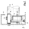
- FIGS. 1 and 2 show the intermediate roller 1 according to the invention used in a accumulation roller conveyor.
- a frame profile 29 is shown here from the inside of the accumulation roller conveyor (FIG. 1).
- the accumulation roller conveyor consists of two frame profiles 29 running parallel to one another, between which the support rollers 33 are rotatably arranged.
- the support rollers 33 are located on a common axis 34 of each gear 35.
- the axis 34 is fixed to the frame profile 29, with the support roller 33 and gear 35 being rotatably arranged thereon.
- a continuously rotating conveying means here a chain 32, is provided, in which the chain wheel 2 of the intermediate roller 1 engages.
- the sprocket is only indicated in dash-dot lines in FIG. 1 with its tip circle “dkk” and its root circle “dfk”.
- the head circles are identified by the reference symbol “dk” and the base circles by the reference symbol “df”, the additional designations “k” for chain wheel “,” g “for counter gear and” to distinguish the counter gear, the sprocket and the gear on the support roller. z "were selected for gear.
- the tip circle diameter of the sprocket 2 bears the reference symbol "dkk", the root circle diameter of the reference character “dfk”, the tip circle diameter of the counter gear 3 the reference character “dkg” and the root circle diameter of the reference character “dfg”, while the tip circle diameter of the gear 35 bears the reference symbol “dkz” "and whose root diameter bears the reference symbol” dfz ".
- the intermediate roller 1 is formed by the chain wheel 2 and the counter gear 3.
- the intermediate roller 1 is rotatably received within a housing 31 with the common axes 8 and 19 of the chain wheel 2 and the counter gear 3.
- the housing 31 itself in turn has a pivot axis 30 about which the housing 31 itself and the intermediate roller 1, ie the sprocket 2 and the counter gear 3 with their axes 8 and 19, can be pivoted.
- Via the actuator 37 which is activated via a sensor (not indicated here) protruding into the conveyor path of the accumulation roller conveyor, and is attached to the housing 31 of the intermediate roller 1, the intermediate roller 1, or the counter gear 3, is in the engaged or disengaged position with respect to the gear 35 brought the idler roller 33.
- FIGS. 3, 4 and 5 show the intermediate roller 1 detached from the frame profile 29, wherein FIG. 3 shows a view of the intermediate roller 1 according to FIG. 2, but without a section; FIG. 4 shows a view from the direction B indicated in FIG. 3 and FIG. 5 shows a view from the direction C indicated in FIG. 3.
- the intermediate roller 1 consists of the sprocket 2 and the counter gear 3. These are formed in two pieces with each other and inserted into each other, so that their two axes 8 and 19 come to lie coaxially with each other.
- the hub 12 of the chain wheel 2 protrudes beyond the end face 38 to form an extended bearing.
- the hub 12 is extended on the end face 9 facing the counter gear 3 in order to act as a bearing body for the counter gear, the latter having a bearing collar 39 on its end face 20 facing away from the sprocket 2.
- a hub stub 40 stands over the end face 38 of the chain wheel 2 and one with the counter gear 3 is identified by the reference number 39, over the end face 20 thereof.
- FIGS. 6 and 7 show the sprocket wheel 2.
- a bearing collar 10 arranged coaxially to the axis 8 can be seen on the side 9 of the sprocket facing the counter gear.
- the diameter "d" of the bearing collar is visibly smaller than the diameter "dfk” of the root circle 11.
- the hub 12 is also arranged coaxially to the axis 8 and extends perpendicularly from the bearing collar 10. It is designed as a bearing sleeve and has a hub bore 21 for this purpose.
- the diameter "dn" of the hub is dimensioned smaller than the diameter "d" of the bearing collar 10.
- the positive locking elements 4 are designed as webs arranged perpendicular to the chain wheel 2 or bearing collar 10, a shoulder 15 being formed between the upper edge 13 of the positive locking element 4 and the upper edge 14 of the hub 12.
- Chambers 6 are thus formed between the individual positive locking elements 4, which will be discussed in more detail later.
- FIGS 8 and 9 show an embodiment of the counter gear 3.
- the counter gear 3 has on the side 16 facing the sprocket an opening 18 that exposes the cavity 17.
- Concentric about the axis 19 or around the bearing bore 42 in the end wall 20, form-locking elements 5 can again be seen as vertical webs.
- a shoulder 41 is again formed between the upper edge 22 of the counter gear 3 and the upper edge 23 of the positive locking elements 5.
- the inner edges 24 of the interlocking element 5 are aligned with the inner diameter "di" of the bearing bore 42.
- the inner circumferential surface 28 of the counter gear 3 correspond to the outer edges 27 of the interlocking elements 4 of the sprocket 2 and the outer circumferential surface 26 of the bearing collar 10.
- the inner edges 24 of the interlocking elements 5 correspond with the peripheral surface 25 of the hub 12 of the chain wheel 2, so that a plain bearing is formed.
- FIGS. 10 and 11 show a perspective illustration of the chain wheel 2 and the counter gear 3, the same elements being identified by the same reference numerals.
- FIG. 12 shows a section of the assembled chain wheel 2 and counter gear 3, which form the intermediate roller 1.
- FIG. 13 represents a section along the line GG indicated in FIG.
- the chambers 6 are again divided into suitable individual spaces 43 by the positive locking elements 4 and 5, in which the damping element 7 is used.
- the damping element 7 there is no compression of the damping element 7, since no force is applied.
- the counter gear 3 engages in the gear 35 of the support roller 33, the positive locking elements 4 and 5 rotate relative to one another until a corresponding positive locking is achieved. Without the damping element 7, this would be the abutment of a form-fitting element 5 against the form-fitting element 4 or the meeting of the sole parts thereof.
- the arrangement of the damping element 7 excellently dampens the introduction of force, with the parts already being driven immediately, that is to say there is no delay.
- the interlocking elements 4 and 5 can also be of a conical shape in order to give the damping element 7 a uniform pressure.
- an intermediate roller for driving the support roller of accumulating roller conveyors for conveying and unpressurized accumulation of piece goods is created, which by the arrangement of a damping element between the form-locking elements of the intermediate roller forming Sprocket and counter gear, all starting impacts eliminated and almost no drive deceleration.
Abstract
Description
Zwischenrollen werden in Staurollenbahnen eingesetzt. Staurollenbahnen selbst sind Förderanlagen, mit sektionsweise angetriebenen Tragrollen, auf denen das Stückgut bewegt wird. Während der Transportbewegung wirken die Stückgüter auf einen in die Förderbahn ragenden Fühler ein, welche Teile der Antriebseinheiten in Eingriff oder Ausgriff mit den Fördermitteln bringt, um die Förderleistung entsprechend den jeweiligen örtlichen Begebenheiten zu manipulieren.Intermediate rollers are used in accumulation roller conveyors. Accumulation roller conveyors themselves are conveyor systems, with section rollers driven on sections, on which the piece goods are moved. During the transport movement, the piece goods act on a sensor protruding into the conveyor track, which brings parts of the drive units into engagement or disengagement with the conveying means in order to manipulate the conveying performance in accordance with the respective local circumstances.
Es gibt dabei Staurollenbahnen, bei denen die Zwischenrolle ein Kettenrad aufweist, das in einer umlaufenden Kette kämmt. Das mit der Tragrolle in Antriebsverbindung bringbare Treibrad kann als Zahnrad ausgebildet sein. Hierdurch entsteht eine zweifache formschlüssige Antriebsübertragung, die einerseits in vorteilhafterweise einen sicheren und zügigen Transport des Stückgutes gewährleistet, andererseits in nachteiligerweise bei Blockieren eines Stückgutes zwangsläufig durchdreht, so daß bei hohem Leistungsaufwand Beschädigungen an der Rollenbahn und/oder am Stückgut auftreten können. Ferner ergeben sich beim Einkuppeln Schwierigkeiten, die Zähne in Eingriff zu bringen, was sich durch harte Schläge bemerkbar macht.There are accumulation roller conveyors in which the intermediate roller has a sprocket that meshes in a rotating chain. The drive wheel which can be brought into drive connection with the support roller can be designed as a gear wheel. This results in a double positive drive transmission, which on the one hand advantageously ensures safe and rapid transport of the piece goods, and on the other hand inevitably turns in a disadvantageous manner when a piece goods are blocked, so that damage to the roller conveyor and / or the piece goods can occur with high power expenditure. Furthermore, there are difficulties in engaging the teeth when engaging, which is noticeable by hard impacts.
Aus der DE-PS 26 50 205 ist eine Staurollenbahn bekannt, welche derart konzipiert ist, daß beim Anfahren eine weitestgehende Unempfindlichkeit gegen Störungen und gleichzeitig eine hohe konstante Antriebskraftübertragung vorliegt. Hier wird eine Kombination von Rutschkupplung und spezieller Verzahnung eine zuverlässige Überlastsicherung bei ein- und ausrastbarer formschlüssiger Antriebskraftübertragung erreicht.From DE-PS 26 50 205 a accumulation roller conveyor is known, which is designed in such a way that when starting a largely insensitivity to interference and at the same time a high constant drive force transmission is present. Here, a combination of slip clutch and special toothing ensures reliable overload protection with positive drive power transmission that can be engaged and disengaged.
Gemäß der DE-PS 26 50 205 sieht die Staurollenbahn das Stückgut tragende Tragrollen vor, die von je einer in einem in eine umlaufende Kette eingreifenden Kettenrad ausgestatteten Zwischenrolle angetrieben werden, wobei die Zwischenrolle durch ein mit einem in die Bahn des Stückgutes ragenden Fühlers versehenen Gestänge aus einer Antriebs- in eine Freilaufstellung gestellt wird. Gemäß der Lehre des deutschen Patentes 26 50 205 ist nun vorgesehen, daß die Verbindung zwischen dem Mantel und der von der Zwischenrolle angetriebenen Nabe der Tragrolle in an sich bekannter Weise als Gleitlager und die Antriebsverbindung zwischen der Zwischenrolle und der Tragrolle als abgeflachte Verzahnung ausgebildet ist.According to DE-PS 26 50 205, the accumulation roller conveyor provides carrying rollers carrying the piece goods, each of which is driven by an intermediate roller equipped in a chain wheel engaging in a rotating chain, the intermediate roller being provided with a linkage which projects into the path of the piece goods from a drive to a freewheel position. According to the teaching of
Gemäß einer solchen Staurollenbahn wurden hinsichtlich der Kraftübertragung beste Ergebnisse erreicht.According to such an accumulation roller conveyor, the best results were achieved in terms of power transmission.
Hinsichtlich des Anfahrens, d.h. dem Zeitpunkt bei dem die Tragrolle in Rotation versetzt wird, kann es jedoch noch zu "Anfahrschlägen" kommen.With regard to starting, i.e. the moment at which the idler roller is set in rotation, there may still be "starting impacts".
Der vorliegenden Erfindung liegt daher die Aufgabe zugrunde, eine Zwischenrolle zu schaffen, bei der die auftretenden Kräfte beim Anfahren der Anlage bzw. der Rollen gedämpft wird.The present invention is therefore based on the object of creating an intermediate roller in which the forces occurring when starting up the system or the rollers are damped.
Diese Aufgabe wird erfindungsgemäß durch eine Zwischenrolle nach dem vorgeschlagenen Anspruch 1 gelöst.This object is achieved according to the invention by an intermediate roller according to the proposed
Besondere Weiterbildungen der Erfindung sind in den Unteransprüchen gekennzeichnet.Particular developments of the invention are characterized in the subclaims.
Gemäß der vorliegenden Erfindung wird nun von einer Zwischenrolle für den Antrieb der Tragrolle von Staurollenbahnen zum Fördern und drucklosen Stauen von Stückgut ausgegangen, wobei die Zwischenrolle in eine Antriebs- und Freilaufstellung bringbar ist und aus einem Kettenrad und einem Gegenzahnrad zum Eingriff in einen mit der Tragrolle verbundenen Zahnrad besteht und derart ausgebildet ist, daß das die Zwischenrolle bildende Kettenrad und das Gegenzahnrad zweiteilig ausgebildet und koaxial ineinander einsteckbar sind und jeweils miteinander korrespondierende Formschlußelemente aufweisen, die unter Bildung mindestens einer Kammer zur Aufnahme mindestens eines Dämpfungselementes mit einem Verdrehspiel einander zuordenbar sind.According to the present invention, an intermediate roller for driving the support roller of accumulating roller conveyors for conveying and unpressurized accumulation of piece goods is now assumed, the intermediate roller being able to be brought into a drive and freewheeling position and consisting of a sprocket and a counter gear for engagement in one with the support roller connected gear and is designed such that the sprocket forming the intermediate roller and the counter gear are formed in two parts and can be inserted coaxially into one another and each have corresponding interlocking elements which can be assigned to one another with a backlash to form at least one chamber for receiving at least one damping element.
Das Kettenrad und das Gegenzahnrad bilden miteinander ein Gleitlager, wobei beide begrenzt zueinander verdrehbar sind. Die Begrenzung erfolgt durch die vorgenannten Formschlußelemente, die sich ineinander verzahnen, jedoch vor Erreichen eines Formschlusses bzw. vor dem gegenseitigen Anschlagen ein Verdrehen beider Teile, d.h. des Kettenrades und des Gegenzahnrades erlauben. Dies ist dadurch gewährleistet, daß die Formschlußelemente beim Ineinanderstecken des Gegenzahnrades und des Kettenrades nicht sofort aufgrund ihrer geometrischen Ausdehnung in Formschluß kommen, sondern erst bei Verdrehen beider Teile zueinander, was daraus resultiert, daß beide miteinander korrespondierenden Formschlußelemente des Kettenrades und des Gegenzahnrades von ihrer Dicke her kleiner dimensioniert sind, als die gewünschte Verdrehbahnlänge.The sprocket and the counter gear together form a slide bearing, both of which can be rotated to a limited extent. The limitation is made by the above-mentioned positive locking elements, which interlock with each other, but before reaching a positive locking or before each other, both parts are twisted, i.e. allow the sprocket and the counter gear. This is ensured by the fact that the interlocking elements do not immediately come into positive engagement when the counter gear and the sprocket are plugged into one another due to their geometrical expansion, but only when the two parts are rotated relative to one another, which results from the fact that the two corresponding interlocking elements of the sprocket and the counter gear have a thickness are dimensioned smaller than the desired twist path length.
Zwischen den Formschlußelementen werden Kammern oder Räume gebildet, die in ihrem Volumen durch Verdrehung des Gegenzahnrades zum Kettenrad reduzierbar oder vergrößerbar sind.Chambers or rooms become between the positive locking elements formed, the volume of which can be reduced or enlarged by rotating the counter gear to the sprocket.
Erfindungsgemäß werden nun in diese Räume Dämpfungselemente eingelegt, die von kompressiblem Wesen sind. Beim Anlaufen der Rollen wird nun durch Verdrehen des Gegenzahnrades zum Kettenrad das Dämpfungselement gepreßt und der sogenannte "Anfahrschlag" genommen, da die auftretenden Kräfte sich auf das Dämpfungselement übertragen und dieses so zu sagen "weich" zusammenpressen, bis letztendlich der Formschluß durch einen Übergang der Einleitungskräfte erreicht ist.According to the invention, damping elements which are of compressible nature are now inserted into these spaces. When the rollers start up, the damping element is pressed by turning the counter gear to the sprocket and the so-called "start-up stroke" is taken, since the forces that occur are transmitted to the damping element and compress it so to speak, "softly", until finally the positive engagement by a transition from Introductory forces are reached.
In einem besonderen Ausführungsbeispiel der Erfindung sieht das Kettenrad koaxial zu seiner Achse auf der zum Gegenrand zugewandten Seite einen Lagerbund vor, welcher kreiszylindrisch ausgebildet ist. Der Durchmesser dieses Lagerbundes ist kleiner dimensioniert, als der Durchmesser des Fußkreises des Kettenrades. Die Nabe des Kettenrades ist als Lagerhülse ausgebildet und vom Durchmesser her kleiner dimensioniert als der Durchmesser des Lagerbundes. Nabe und Lagerbund des Kettenrades sind einander koaxial zugeordnet, wobei die Formschlußelemente auf dem Lagerbund konzentrisch um die Achse der Nabe angeordnet sind. Bevorzugterweise sind diese Formschlußelemente als senkrecht zum Kettenrad bzw. Lagerbund angeordnete Stege ausgebildet, wobei deren Oberkante etwas von der Oberkante der Nabe zurückversetzt ist.In a special embodiment of the invention, the sprocket provides a bearing collar which is circular cylindrical and coaxial with its axis on the side facing the opposite edge. The diameter of this bearing collar is dimensioned smaller than the diameter of the base circle of the chain wheel. The hub of the chain wheel is designed as a bearing sleeve and its diameter is smaller than the diameter of the bearing collar. The hub and the bearing collar of the chain wheel are coaxially assigned to one another, the positive locking elements being arranged on the bearing collar concentrically around the axis of the hub. These form-locking elements are preferably designed as webs arranged perpendicular to the chain wheel or bearing collar, the upper edge of which is set back somewhat from the upper edge of the hub.
Das Kettenrad, der Lagerbund, die Nabe und die Formschlußelemente sind zusammen als einstückiges Kunststoffteil ausgebildet.The sprocket, the bearing collar, the hub and the positive locking elements are formed together as a one-piece plastic part.
Das Gegenzahnrad ist als Hohlkörper ausgebildet und besitzt auf einer Seite eine den Hohlraum freigebende Öffnung, in die das Kettenrad nebst Lagerbund und Formschlußelemente einführbar ist, so daß das Kettenrad und das Gegenzahnrad koaxial ineinander einsetzbar sind.The counter gear is designed as a hollow body and has on one side an opening exposing the cavity, into which the sprocket together with the bearing collar and form-locking elements can be inserted, so that the sprocket and the counter gear can be inserted coaxially into one another.
Die gegenüberliegende Seite des Gegenzahnrades ist mit einer Stirnwand geschlossen und von einer Lagerbohrung durchsetzt, in welcher die Nabe des Kettenrades zu liegen kommt. Innerhalb des Hohlraumes des Gegenzahnrades sind konzentrisch um deren Achse bzw. die Lagerbohrung radial verteilte Formschlußelemente angeordnet; welche bevorzugterweise wiederum als senkrecht zur Stirnwand angeordnete Stege ausgebildet sind. Die Oberkante der Stege ist wiederum von der Oberkante des Gegenzahnrades bzw. von der Öffnung etwas zurückversetzt. Die Innenkanten dieser Formschlußelemente des Gegenzahnrades fluchten mit der Lagerbohrung, so daß diese quasi einen gleichen und identischen Innendurchmesser aufweisen. Auch das Gegenzahnrad mit seinen Formschlußelementen ist als einstückiges Kunststoffteil ausgebildet. Die Innenkanten der Formschlußelemente des Gegenzahnrades dienen als Lagerschalenteile für die Nabe des Kettenrades. Ebenso fungiert der Innendurchmesser des Hohlraumes des Kettenzahnrades als Lagerschale zur Aufnahme des Lagerbundes des Kettenrades sowie den dort angeordneten Formschlußelementen, so daß beide Teile, das Gegenzahnrad und das Kettenrad als Gleitlager miteinander arbeiten, wobei jedoch die Verdrehfreiheit durch die Formschlußelemente begrenzt ist, da diese nach einem begrenzten Verdrehweg aneinander anschlagen bzw. unmittelbar, durch Trennung des Dämpfungselementes formschlüssig aufeinandertreffen.The opposite side of the counter gear is closed with an end wall and penetrated by a bearing bore in which the hub of the chain wheel comes to rest. Radially distributed positive locking elements are arranged concentrically around the axis or the bearing bore within the cavity of the counter gear; which in turn are preferably designed as webs arranged perpendicular to the end wall. The upper edge of the webs is in turn slightly set back from the upper edge of the counter gear or from the opening. The inner edges of these positive locking elements of the counter gear align with the bearing bore, so that they have a quasi identical and identical inside diameter. The counter gear with its positive locking elements is also formed as a one-piece plastic part. The inner edges of the positive locking elements of the counter gear serve as bearing shell parts for the hub of the chain wheel. Likewise, the inner diameter of the cavity of the sprocket wheel acts as a bearing shell for receiving the bearing collar of the sprocket and the interlocking elements arranged there, so that both parts, the counter gear and the sprocket work as a sliding bearing, but the freedom from rotation is limited by the interlocking elements, since these abut a limited torsion path or meet one another directly, by separating the damping element.
Anhand der beigefügten Zeichnungen, die ein besonders bevorzugtes Ausführungsbeispiel der Erfindung zeigen, wird diese nun näher beschrieben. Dabei zeigen:
Figur 1- eine Innenansicht eines die Zwischenrolle aufnehmenden Rahmenprofils;
Figur 2- einen Schnitt entlang der in
Figur 1 angedeuteten Linie A-A; Figur 3- die aus dem Rahmenprofil separierte Zwischenrolle in einer Ansicht;
Figur 4- die Zwischenrolle aus der in
Figur 3 angedeuteten Richtung B; Figur 5- die Zwischenrolle aus der in
Figur 3 angedeutenen Richtung C; Figur 6- das Kettenrad;
- Figur 7
- einen Schnitt durch das Kettenrad entlang der in
Figur 6 angedeuteten Linie D-D; Figur 8- das Gegenzahnrad;
Figur 9- das Gegenzahnrad entlang der in
Figur 8 angedeuteten Schnittlinie E-E; Figur 10- eine perspektivische Darstellung des Kettenrades;
- Figur 11
- eine perspektivische Darstellung des Gegenzahnrades;
Figur 12- einen Schnitt entlang der in
Figur 4 angedeuteten Linie F-F des ineinander greifenden Kettenrades und Gegenzahnrades, welche die Zwischenrolle bilden. Figur 13- einen Schnitt entlang der in
Figur 12 angedeuteten Linie G-G.
- Figure 1
- an interior view of a frame profile receiving the intermediate roller;
- Figure 2
- a section along the line AA indicated in Figure 1;
- Figure 3
- the intermediate roller separated from the frame profile in one view;
- Figure 4
- the intermediate roller from the direction B indicated in Figure 3;
- Figure 5
- the intermediate roller from the direction C indicated in Figure 3;
- Figure 6
- the sprocket;
- Figure 7
- a section through the sprocket along the line DD indicated in Figure 6;
- Figure 8
- the counter gear;
- Figure 9
- the counter gear along the section line EE indicated in Figure 8;
- Figure 10
- a perspective view of the sprocket;
- Figure 11
- a perspective view of the counter gear;
- Figure 12
- a section along the line FF indicated in Figure 4 of the intermeshing sprocket and counter gear, which form the intermediate roller.
- Figure 13
- a section along the line GG indicated in Figure 12.
Die Figuren 1 und 2 zeigen die, in einer Staurollenbahn eingesetzte erfindungsgemäße Zwischenrolle 1. Es ist hier ein Rahmenprofil 29 von der Innenseite der Staurollenbahn her abgebildet (Figur 1). Die Staurollenbahn besteht aus zwei parallel zueinander verlaufenden Rahmenprofilen 29 zwischen denen die Tragrollen 33 drehbar angeordnet sind. Hierzu befinden sich die Tragrollen 33 auf einer gemeinsamen Achse 34 jeweils eines Zahnrades 35. Die Achse 34 ist am Rahmenprofil 29 fixiert, wobei Tragrolle 33 und Zahnrad 35 drehbar auf dieser angeordnet sind. Zwischen Tragrolle 33 bzw. Zahnrad 35 und dem unteren Flansch 36 des Rahmenprofiles 29 ist ein ständig umlaufendes Fördermittel, hier eine Kette 32 vorgesehen, in welche das Kettenrad 2 der Zwischenrolle 1 eingreift. Das Kettenrad ist in Figur 1 der Einfachheit halber lediglich mit seinem Kopfkreis "dkk" und seinem Fußkreis "dfk" strichpunktliniert angedeutet.FIGS. 1 and 2 show the
Ebenso das Gegenzahnrad 3, welches in das Zahnrad 35 in Eingriff bringbar ist. Auch beim Zahnrad 35 wurde der Kopfkreis und der Fußkreis lediglich strichpunktliniert angedeutet.Likewise, the
Die Kopfkreise sind mit den Bezugszeichen "dk" und die Fußkreise mit dem Bezugszeichen "df" gekennzeichnet, wobei zur Unterscheidung des Gegenzahnrades, des Kettenrades und des Zahnrades auf der Tragrolle die Zusatzbezeichnungen "k" für Kettenrad", "g" für Gegenzahnrad und "z" für Zahnrad gewählt wurden.The head circles are identified by the reference symbol "dk" and the base circles by the reference symbol "df", the additional designations "k" for chain wheel "," g "for counter gear and" to distinguish the counter gear, the sprocket and the gear on the support roller. z "were selected for gear.
Somit trägt der Kopfkreisdurchmesser des Kettenrades 2 das Bezugszeichen "dkk", dessen Fußkreisdurchmesser das Bezugszeichen "dfk", der Kopfkreisdurchmesser des Gegenzahnrades 3 das Bezugszeichen "dkg" und dessen Fußkreisdurchmesser das Bezugszeichen "dfg", während der Kopfkreisdurchmesser des Zahnrades 35 das Bezugszeichen "dkz" und dessen Fußkreisdurchmesser das Bezugszeichen "dfz" trägt.Thus, the tip circle diameter of the
Die Zwischenrolle 1 wird durch das Kettenrad 2 und das Gegenzahnrad 3 gebildet. Die Zwischenrolle 1 ist mit den gemeinsamen Achsen 8 und 19 des Kettenrades 2 und des Gegenzahnrades 3, drehbar innerhalb eines Gehäuses 31 aufgenommen. Das Gehäuse 31 selbst weist wiederum eine Schwenkachse 30 auf, um welche das Gehäuse 31 selbst, sowie die Zwischenrolle 1, d.h. das Kettenrad 2 und das Gegenzahnrad 3 mit ihren Achsen 8 und 19 schwenkbar ist. Über das Stellglied 37, welches über einen hier nicht angedeuteten, in die Förderbahn der Staurollenbahn einragenden Fühler aktiviert wird, und am Gehäuse 31 der Zwischenrolle 1 befestigt ist, wird die Zwischenrolle 1, bzw. das Gegenzahnrad 3 in Eingriff- oder Ausgriffstellung gegenüber dem Zahnrad 35 der Tragrolle 33 gebracht.The
Durch diese Konfiguration der Antriebsteile und angetriebenen Teile bleibt das Kettenrad 2 ständig in Eingriff mit der Kette 32.With this configuration of the drive parts and driven parts, the
Die Figuren 3, 4 und 5 zeigen die aus dem Rahmenprofil 29 herausgelöste Zwischenrolle 1, wobei die Figur 3 eine Ansicht der Zwischenrolle 1 darstellt gemäß der Figur 2, jedoch ohne Schnittverlauf; die Figur 4 eine Ansicht aus der in Figur 3 angedeuteten Richtung B und die Figur 5 eine Ansicht aus der in Figur 3 angedeuteten Richtung C.FIGS. 3, 4 and 5 show the
Die Zwischenrolle 1 besteht aus dem Kettenrad 2 und dem Gegenzahnrad 3. Diese sind miteinander zweistückig ausgebildet und ineinander eingesteckt, so daß deren beiden Achsen 8 und 19 koaxial zueinander zu liegen kommen.The
Die Nabe 12 des Kettenrades 2 ragt dabei über die Stirnfläche 38 hinaus, um ein verlängertes Lager zu bilden. Aus gleichem Grunde ist die Nabe 12 auf der dem Gegenzahnrad 3 zugewandte Stirnseite 9 verlängert, um als Lagerkörper für das Gegenzahnrad zu fungieren, wobei letzteres an seiner dem Kettenrad 2 weggewandten Stirnseite 20 einen Lagerbund 39 besitzt. Somit steht über die Stirnseite 38 des Kettenrades 2 ein Nabenbundstummel 40 und beim Gegenzahnrad 3 ein solcher mit dem Bezugszeichen 39 gekennzeichnet, über dessen Stirnseite 20 über.The
In der Figur 4 ist darüberhinaus erkennbar, daß der Kopfkreis "dkk" des Kettenrades 2 die größte Ausdehnung dieser Zwischenrolle 1 darstellt, während das Gegenzahnrad 3 bzw. dessen Kopfkreisdurchmesser "dkg" unterhalb des Fußkreisdurchmessers "dfk" des Kettenrades 2 zu liegen kommt. Ferner ist aus dieser Abbildung der Lagerbund 39 des Gegenzahnrades 3 und die Nabe 12 des Kettenrades 2 mit ihrer Lagerbohrung 21 zu erkennen.In Figure 4 it can also be seen that the tip circle "dkk" of the
Die Figuren 6 und 7 zeigen das Kettenzahnrad 2. Auf der zum Gegenzahnrad zugewandten Seite 9 des Kettenrades ist ein koaxial zur Achse 8 angeordneter Lagerbund 10 zu erkennen. Der Durchmesser "d" des Lagerbundes ist sichtbar kleiner dimensioniert, als der Durchmesser "dfk" des Fußkreises 11. Die Nabe 12 ist ebenfalls koaxial zur Achse 8 angeordnet und erstreckt sich vom Lagerbund 10 senkrecht. Sie ist als Lagerhülse ausgebildet und weist zu diesem Zwecke eine Nabenbohrung 21 auf. Wie bereits dargelegt, ist der Duchmesser "dn" der Nabe kleiner dimensioniert als der Durchmesser "d" des Lagerbundes 10. Die Außenumfangsfläche 26 sowie die Außenkante 27 der radial auf dem Lagerbund 10 um die Nabe 12 verteilten Formschlußelemente 4 bilden hierbei in Zusammenspiel mit dem Gegenzahnrad entsprechende Gleitlagerelemente. In diesem Ausführungsbeispiel sind die Formschlußelemente 4 als senkrecht zum Kettenrad 2 bzw. Lagerbund 10 angeordnete Stege ausgebildet, wobei zwischen Oberkante 13 des Formschlußelementes 4 und Oberkante 14 der Nabe 12 ein Absatz 15 gebildet ist.FIGS. 6 and 7 show the
Zwischen den einzelnen Formschlußelementen 4 werden somit Kammern 6 gebildet, auf die später noch näher eingegangen wird.
Die Figuren 8 und 9 zeigen ein Ausführungsbeispiel des Gegenzahnrades 3. Hier ist deutlich zu erkennen, daß dieses als Hohlkörper ausgebildet ist. Das Gegenzahnrad 3 besitzt an der zum Kettenrad zugewandten Seite 16 eine den Hohlraum 17 freiliegende Öffnung 18. Konzentrisch um die Achse 19 bzw. um die Lagerbohrung 42 in der Stirnwand 20, sind wiederum als senkrechte Stege ausgebildete Formschlußelemente 5 zu erkennen.Figures 8 and 9 show an embodiment of the
Auch hier werden wieder einzelne Kammern 6 gebildet.
Zwischen der Oberkante 22 des Gegenzahnrades 3 und der Oberkante 23 der Formschlußelemente 5 ist wiederum ein Absatz 41 gebildet. Die Innenkanten 24 des Formschlußelementes 5 fluchten dabei mit dem Innendurchmesser "di" der Lagerbohrung 42. Die Innenumfangsfläche 28 des Gegenzahnrades 3 korrespondieren mit den Außenkanten 27 der Formschlußelemente 4 des Kettenrades 2 und der Außenumfangsfläche 26 des Lagerbundes 10. Die Innenkanten 24 der Formschlußelemente 5 korrespondieren mit der Umfangsfläche 25 der Nabe 12 des Kettenrades 2, so daß ein Gleitlager gebildet ist.A
Die Figuren 10 und 11 zeigen perspektivische Darstellung des Kettenrades 2 bzw. des Gegenzahnrades 3, wobei gleiche Elemente mit den gleichen Bezugszeichen gekennzeichnet sind.FIGS. 10 and 11 show a perspective illustration of the
Die Figur 12 zeigt einen Schnitt des zusammengefügten Kettenrades 2 und Gegenzahnrades 3, welche die Zwischenrolle 1 bilden.FIG. 12 shows a section of the assembled
Auch hier sind die gleichen Elemente mit den gleichen Bezugszeichen gekennzeichnet, wobei hier zusätzlich das Dämpfungselement mit dem Bezugszeichen 7 gekennzeichnet ist. Das Lageverhältnis und das Verdrehspiel geht nochmals deutlich aus der Figur 13 hervor, welche einen Schnitt entlang der in Figur 12 angedeuteten Linie G-G darstellt.Here, too, the same elements are identified by the same reference symbols, with the addition here Damping element is identified by the reference numeral 7. The positional relationship and the backlash are again clearly shown in FIG. 13, which represents a section along the line GG indicated in FIG.
In zusammengefügtem Stadium des Kettenrades 2 und Gegenzahnrades 3 werden die Kammern 6 durch die Formschlußelemente 4 bzw. 5 nochmals in geeignete Einzelräume 43 unterteilt, in denen das Dämpfungselement 7 eingesetzt wird. In der hier dargestellten Situation liegt keine Pressung des Dämpfungselementes 7 vor, da keine Krafteinleitung erfolgt. Greift das Gegenzahnrad 3 in das Zahnrad 35 der Tragrolle 33 ein, so verdrehen sich die Formschlußelemente 4 bzw. 5 zueinander bis ein entsprechender Formschluß erreicht ist. Ohne Dämpfungselement 7 wäre dies der Anschlag eines Formschlußelementes 5 an das Formschlußelement 4 bzw. das Zusammentreffen deren Sohlenteile. Durch die Anordnung des Dämpfungselementes 7 wird die krafteinleitung hervorragend gedämpft, wobei bereits sofort eine Antriebsbewegung der Teile erfolgt, also keine Verzögerung vorliegt.In the assembled stage of the
Wie in der Figur 13a dargestellt, können die Formschlußelemente 4 bzw. 5 auch von konischer Gestalt sein, um dem Dämpfungselement 7 eine gleichmäßige Pressung zu verleihen.As shown in FIG. 13a, the interlocking
Mit der vorliegenden Erfindung wird eine Zwischenrolle für den Antrieb der Tragrolle von Staurollenbahnen zum Fördern und drucklosen Stauen von Stückgut geschaffen, die durch die Anordnung eines Dämpfungselementes zwischen den Formschlußelementen der, die Zwischenrolle bildenden Kettenrades und Gegenzahnrades, jegliche Anfahrschläge eliminiert und dabei nahezu keine Antriebsverzögerung besitzt.With the present invention, an intermediate roller for driving the support roller of accumulating roller conveyors for conveying and unpressurized accumulation of piece goods is created, which by the arrangement of a damping element between the form-locking elements of the intermediate roller forming Sprocket and counter gear, all starting impacts eliminated and almost no drive deceleration.
- 11
- ZwischenrolleIntermediate role
- 22nd
- KettenradSprocket
- 33rd
- GegenzahnradCounter gear
- 44th
- Formschlußelement von 2Positive locking element from 2
- 55
- Formschlußelement von 3Positive locking element from 3
- 66
- Kammerchamber
- 77
- DämpfungselementDamping element
- 88th
- Achse von 2Axis of 2nd
- 99
- Stirnseite von 2Front of 2
- 1010th
- Lagerbund von 2Warehouse from 2
- 1111
- Fußkreis von 2Foot circle of 2
- 1212th
- Nabe von 2Hub of 2
- 1313
- Oberkante von 4Top edge of 4
- 1414
- Oberkante von 12Top edge of 12
- 1515
- Absatz zwischen 13 und 14Paragraph between 13 and 14
- 1616
- Stirnseite von 3Front of 3
- 1717th
- Hohlraum von 3Cavity of 3
- 1818th
- Öffnung von 3Opening of 3rd
- 1919th
- Achse von 3Axis of 3
- 2020th
- Stirnwand von 3Front wall of 3
- 2121
- Lagerbohrung von 2Bearing bore from 2
- 2222
- Oberkante von 3Top edge of 3
- 2323
- Oberkante von 5Top edge of 5
- 2424th
- Innenkante von 5Inner edge of 5
- 2525th
- Außenumfangsfläche von 12Outer peripheral surface of 12
- 2626
- Außenumfangsfläche von 10Outer peripheral area of 10
- 2727
- Außenkante von 4Outer edge of 4
- 2828
- Innenumfangsfläche von 3Inner circumferential surface of 3
- 2929
- RahmenprofilFrame profile
- 3030th
- SchwenkachseSwivel axis
Claims (36)
dadurch gekennzeichnet,
daß das die Zwischenrolle (1) bildende Kettenrad (2) und das Gegenzahnrad (3) koaxial ineinander einsteckbar sind und jeweils miteinander korrespondierende Formschlußelemente (4,5) aufweisen, die unter Bildung mindestens einer Kammer (6) zur Aufnahme mindestens eines Dämpfungselementes (7) mit einem Verdrehspiel einander zuordenbar sind.Intermediate roller for driving the idler roller conveyor rollers for conveying and unpressurized accumulation of piece goods, the intermediate roller being able to be brought into a drive and freewheeling position and consisting of a chain wheel and a counter gear for engagement with a gear wheel connected to the idler roller,
characterized,
that the sprocket (2) forming the intermediate roller (1) and the counter gear (3) can be inserted coaxially into one another and each have corresponding interlocking elements (4, 5) which form at least one chamber (6) for receiving at least one damping element (7 ) can be assigned to each other with a backlash.
dadurch gekennzeichnet,
daß das Kettenrad (2) koaxial zu seiner Achse (8) auf der zum Gegenrad (3) zugewandten Seite (9) einen Lagerbund (10) aufweist.Intermediate roller according to claim 1,
characterized,
that the sprocket (2) coaxial with its axis (8) on the side facing the counter wheel (3) (9) has a bearing collar (10).
dadurch gekennzeichnet,
daß der Lagerbund (10) kreiszylindrisch ausgebildet ist.Intermediate roller according to claim 2,
characterized,
that the bearing collar (10) is circular cylindrical.
dadurch gekennzeichnet,
daß der Durchmesser "d" des Lagerbundes (10) kleiner dimensioniert ist, als der Durchmesser "dfk" des Fußkreises (11) des Kettenrades (2).Intermediate roller according to at least one of claims 2 and 3,
characterized,
that the diameter "d" of the bearing collar (10) is dimensioned smaller than the diameter "dfk" of the root circle (11) of the chain wheel (2).
dadurch gekennzeichnet,
daß die Nabe (12) des Kettenrades (2) als Lagerhülse ausgebildet ist.Intermediate roller according to at least one of claims 1 to 4,
characterized,
that the hub (12) of the chain wheel (2) is designed as a bearing sleeve.
dadurch gekennzeichnet,
daß der Durchmesser "dn" der Nabe (12) kleiner dimensioniert ist, als der Durchmesser "d" des Lagerbundes (10).Intermediate roller according to claim 5,
characterized,
that the diameter "dn" of the hub (12) is dimensioned smaller than the diameter "d" of the bearing collar (10).
dadurch gekennzeichnet,
daß die Nabe (12) und der Lagerbund (10) des Kettenrades (2) koaxial einander zugeordnet sind.Intermediate roller according to claim 1 to 6,
characterized,
that the hub (12) and the bearing collar (10) of the chain wheel (2) are coaxially assigned to each other.
dadurch gekennzeichnet,
daß die Formschlußelemente (4) des Kettenrades (2) auf dem Lagerbund (10) konzentrisch um die Achse (8) und die Nabe (12) angeordnet sind.Intermediate roller according to claim 1 to 7,
characterized,
that the positive locking elements (4) of the chain wheel (2) on the bearing collar (10) are arranged concentrically around the axis (8) and the hub (12).
dadurch gekennzeichnet,
daß die Formschlußelemente (4) als senkrecht zum Kettenrad (2) bzw. Lagerbund (10) angeordnete Stege ausgebildet sind.Intermediate roller according to claim 8,
characterized,
that the positive locking elements (4) are designed as webs arranged perpendicular to the chain wheel (2) or bearing collar (10).
dadurch gekennzeichnet,
daß zwischen Oberkante (13) des Formschlußelementes (4) und Oberkante (14) der Nabe (12) ein Absatz (15) gebildet ist.Intermediate roller according to claim 8 and 9,
characterized,
that between the upper edge (13) of the form-fitting element (4) and the upper edge (14) of the hub (12) a shoulder (15) is formed.
dadurch gekennzeichnet,
daß als Formschlußelement (4), vier konzentrisch um die Achse (8) bzw. Nabe (12) auf dem Lagerbund (10) radial verteilte Stege angeordnet sind.Intermediate roller according to claim 1 to 10,
characterized,
that as a positive locking element (4), four concentrically around the axis (8) or hub (12) on the bearing collar (10) radially distributed webs are arranged.
dadurch gekennzeichnet,
daß das Kettenrad (2), der Lagerbund (10), die Nabe (12) und die Formschlußelemente (4) miteinander einstückig ausgebildet sind.Intermediate roller according to claim 1 to 11,
characterized,
that the chain wheel (2), the bearing collar (10), the hub (12) and the positive locking elements (4) are integrally formed with each other.
dadurch gekennzeichnet,
daß das Kettenrad (2), der Lagerbund (10), die Nabe (12) und die Formschlußelemente (4) als einstückiges Kunststoffteil ausgebildet sind.Intermediate roller according to claim 12,
characterized,
that the chain wheel (2), the bearing collar (10), the hub (12) and the form-fitting elements (4) are designed as a one-piece plastic part.
dadurch gekennzeichnet,
daß das Gegenzahnrad (3) als Hohlkörper ausgebildet ist.Intermediate roller according to claim 1,
characterized,
that the counter gear (3) is designed as a hollow body.
dadurch gekennzeichnet,
daß das Gegenzahnrad (3) an der zum Kettenrad (2) zugewandten Seite (16), eine den Hohlraum (17) freilegende Öffnung (18) aufweist.Intermediate roller according to claims 1 and 14,
characterized,
that the counter gear (3) on the side facing the sprocket (2) (16) has an opening (18) exposing the cavity (17).
dadurch gekennzeichnet,
daß das Gegenzahnrad (3) eine koaxial der Achse (8) des Kettenrades (2) zuordenbare Achse (19) aufweist.Intermediate roller according to at least one of the preceding claims,
characterized,
that the counter gear (3) has an axis (19) which can be assigned coaxially to the axis (8) of the chain wheel (2).
dadurch gekennzeichnet,
daß die dem Kettenrad (2) weggewandte Stirnwand (20) des Gegenzahnrades (3) von einer Lagerbohrung (42) durchsetzt ist.Intermediate roller according to claim 1, 14 to 16,
characterized,
that the end wall (20) of the counter gear (3) facing away from the chain wheel (2) is penetrated by a bearing bore (42).
dadurch gekennzeichnet,
daß innerhalb des Hohlraumes (17) des Gegenzahnrades (3) konzentrisch um die Achse (19) bzw. die Lagerbohrung (42) radial verteilte Formschlußelemente (5) angeordnet sind.Intermediate roller according to claim 1, 14 to 17,
characterized,
that radially distributed positive locking elements (5) are arranged within the cavity (17) of the counter gear (3) concentrically around the axis (19) or the bearing bore (42).
dadurch gekennzeichnet,
daß die Formschlußelemente (5) des Gegenzahnrades (3) als senkrecht zur Stirnwand (20) des Gegenzahnrades (3) angeordnete Stege ausgebildet sind.Intermediate roller according to claim 18,
characterized,
that the positive locking elements (5) of the counter gear (3) are designed as webs arranged perpendicular to the end wall (20) of the counter gear (3).
dadurch gekennzeichnet,
daß zwischen Oberkante (22) des Gegenzahnrades (3) und Oberkante (23) der Formschlußelemente (5) ein Absatz (41) vorliegt.Intermediate roller according to claim 18 and 19,
characterized,
that there is a shoulder (41) between the upper edge (22) of the counter gear (3) and the upper edge (23) of the positive locking elements (5).
dadurch gekennzeichnet,
daß die Innenkante (24) des Formschlußelementes (5) mit dem Innendurchmesser "di" der Lagerbohrung (42) des Gegenzahnrades (3) fluchtet.Intermediate roller according to at least one of the preceding claims,
characterized,
that the inner edge (24) of the form-locking element (5) with the inner diameter "di" of the bearing bore (42) of the counter gear (3) is aligned.
dadurch gekennzeichnet,
daß das Gegenzahnrad (3) mit Stirnwand (20) und Formschlußelementen (5) einstückig ausgebildet sind.Intermediate roller according to at least one of the preceding claims,
characterized,
that the counter gear (3) with end wall (20) and positive locking elements (5) are integrally formed.
dadurch gekennzeichnet,
daß das Gegenzahnrad (3) mit Formschlußelementen (5) und Stirnwand (20) als einstückiges Kunststoffteil ausgebildet ist.Intermediate roller according to claim 22,
characterized,
that the counter gear (3) with positive locking elements (5) and end wall (20) is formed as a one-piece plastic part.
dadurch gekennzeichnet,
daß als Formschlußelemente (5), vier im Hohlraum (17) des Gegenzahnrades (3) radial verteilte Stege angeordnet sind.Intermediate roller according to at least one of claims 1 to 23,
characterized,
that are arranged as positive locking elements (5), four in the cavity (17) of the counter gear (3) radially distributed webs.
dadurch gekennzeichnet,
daß die Nabe (12) des Kettenrades (2) innerhalb der Lagerbohrung (42) des Gegenzahnrades (3) aufgenommen ist.Intermediate roller according to claim 1 to 24,
characterized,
that the hub (12) of the sprocket (2) is received within the bearing bore (42) of the counter gear (3).
dadurch gekennzeichnet,
daß die Innenkanten (24) der Formschlußelemente (5) des Gegenzahnrades (3) als Lagerschalenteile mit der Außenumfangsfläche (25) der Nabe (12) des Kettenrades (2) korrespondieren.Intermediate roller according to claim 1 to 25,
characterized,
that the inner edges (24) of the form-locking elements (5) of the counter gear (3) correspond to the outer peripheral surface (25) of the hub (12) of the chain wheel (2) as bearing shell parts.
dadurch gekennzeichnet,
daß der Innendurchmesser "dig" des Gegenzahnrades (3) als Lagerschale mit der Außenumfangsfläche (26) des Lagerbundes (10) und den Außenkanten (27) der Formschlußelemente (4) des Kettenrades (2) korrespondieren.Intermediate roller according to claim 1 to 26,
characterized,
that the inner diameter "dig" of the counter gear (3) as a bearing shell with the outer peripheral surface (26) of the bearing collar (10) and the outer edges (27) of the form-locking elements (4) of the sprocket (2) correspond.
dadurch gekennzeichnet,
daß die Innenkanten (24) der Formschlußelemente (5) und die Innenumfangsfläche (28) des Gegenzahnrades (3) mit der Außenkante (27) der Formschlußelemente (4), der Umfangsfläche (26) des Lagerbundes (10) und der Umfangsfläche (25) der Nabe (12) ein Gleitlager bilden.Intermediate roller according to claim 1 to 27,
characterized,
that the inner edges (24) of the positive locking elements (5) and the inner peripheral surface (28) of the counter gear (3) with the outer edge (27) of the positive locking elements (4), the peripheral surface (26) of the bearing collar (10) and the peripheral surface (25) the hub (12) form a plain bearing.
dadurch gekennzeichnet,
daß die Formschlußelemente (5) des Gegenzahnrades (3) und die Formschlußelemente (4) des Kettenrades (2) jeweils in der, zwischen zweier Formschlußteilen (4 oder 5) gebildeten Kammer (6) mit Verdrehspiel zu liegen kommen.Intermediate roller according to claim 1 to 28,
characterized,
that the interlocking elements (5) of the counter gear (3) and the interlocking elements (4) of the sprocket (2) each come to rest in the chamber (6) formed between two interlocking parts (4 or 5) with backlash.
dadurch gekennzeichnet,
daß durch die ineinandergreifenden Formschlußelemente (4 und 5) des Gegenzahnrades (3) und des Kettenrades (2) die Kammern (6) in, zur Aufnahme von Dämpfungselementen (7) geeignete Räume (43) geteilt sind.Intermediate roller according to claim 29,
characterized,
that by the interlocking positive locking elements (4 and 5) of the counter gear (3) and the chain wheel (2), the chambers (6) in, for receiving damping elements (7) suitable spaces (43) are divided.
dadurch gekennzeichnet,
daß das Dämpfungselement (7) aus elastischem Material geschaffen ist.Intermediate roller according to claim 1 to 30,
characterized,
that the damping element (7) is made of elastic material.
dadurch gekennzeichnet,
daß das Dämpfungsmaterial (7) aus einem kompressiblem Material geschaffen ist.Intermediate roller according to claim 1 to 31,
characterized,
that the damping material (7) is made of a compressible material.
dadurch gekennzeichnet,
daß das die Zwischenrolle (1) bildende Kettenrad (2) und Gegenzahnrad (3) mit ihren Achsen (8 und 19) koaxial angeordnet sind und um eine gemeinsame, am Rahmenprofil (29) der Staurollenbahn angeordneten Achse (30) schwenkbar sind.Intermediate roller according to claim 1 to 32,
characterized,
that the sprocket (2) forming the intermediate roller (1) and counter gear (3) with their axes (8 and 19) are arranged coaxially and can be pivoted about a common axis (30) arranged on the frame profile (29) of the accumulating roller conveyor.
dadurch gekennzeichnet,
daß die Zwischenrolle (1) innerhalb eines Gehäuses (31) mit ihrer, durch die koaxial einander zugeordneten Achsen (8 und 19) des Kettenrades (2) und des Gegenzahnrades (3) drehbar gelagert ist und die Achse (30) des Gehäuses (31) schwenkbar aufnimmt.Intermediate roller according to claim 33,
characterized,
that the intermediate roller (1) within a housing (31) with its, by the coaxially assigned axes (8 and 19) of the sprocket (2) and the counter gear (3) is rotatably mounted and the axis (30) of the housing (31 ) pivots.
dadurch gekennzeichnet,
daß das Kettenrad (2) ständig im Eingriff mit einer umlaufenden Kette (32) steht.Intermediate roller according to claim 1 to 34,
characterized,
that the chain wheel (2) is constantly in engagement with a rotating chain (32).
dadurch gekennzeichnet,
daß die Funktion der Nabe (12) des Kettenrades (2) als Lagerhülse, durch eine seperate Lagerbuchse ersetzt wird.Intermediate roller according to at least one of claims 1 to 35,
characterized,
that the function of the hub (12) of the chain wheel (2) as a bearing sleeve is replaced by a separate bearing bush.
Priority Applications (1)
| Application Number | Priority Date | Filing Date | Title |
|---|---|---|---|
| DE9422049U DE9422049U1 (en) | 1993-07-28 | 1994-07-22 | Intermediate roller for driving the idler roller conveyor rollers |
Applications Claiming Priority (2)
| Application Number | Priority Date | Filing Date | Title |
|---|---|---|---|
| DE9311269U | 1993-07-28 | ||
| DE9311269U DE9311269U1 (en) | 1993-07-28 | 1993-07-28 | INTERMEDIATE REEL FOR THE DRIVE OF THE SUPPORT REELS OF DAMPER REELS |
Publications (2)
| Publication Number | Publication Date |
|---|---|
| EP0636558A1 true EP0636558A1 (en) | 1995-02-01 |
| EP0636558B1 EP0636558B1 (en) | 1997-10-22 |
Family
ID=6896125
Family Applications (1)
| Application Number | Title | Priority Date | Filing Date |
|---|---|---|---|
| EP94111450A Expired - Lifetime EP0636558B1 (en) | 1993-07-28 | 1994-07-22 | Intermediate roller for driving support rollers of accumulation roller conveyors |
Country Status (10)
| Country | Link |
|---|---|
| US (1) | US5450945A (en) |
| EP (1) | EP0636558B1 (en) |
| JP (1) | JPH07149414A (en) |
| CN (1) | CN1057273C (en) |
| AT (1) | ATE159498T1 (en) |
| AU (1) | AU660250B2 (en) |
| DE (3) | DE9311269U1 (en) |
| DK (1) | DK0636558T3 (en) |
| ES (1) | ES2111810T3 (en) |
| RU (1) | RU2121952C1 (en) |
Citations (3)
| Publication number | Priority date | Publication date | Assignee | Title |
|---|---|---|---|---|
| DE2650205A1 (en) * | 1976-11-02 | 1978-05-03 | Richard Gebhardt | ACCUMULATION ROLLER CONVEYOR FOR CONVEYING AND PRESSURE-FREE STOWING OF UNIT GOODS |
| US4328879A (en) * | 1978-04-27 | 1982-05-11 | The Gates Rubber Company | Shock-absorbing sprocket, drive assembly, and the like |
| US4416650A (en) * | 1981-06-26 | 1983-11-22 | The E.W. Buschman Company | Drive wheel and sprocket assembly |
Family Cites Families (6)
| Publication number | Priority date | Publication date | Assignee | Title |
|---|---|---|---|---|
| DE2517015C2 (en) * | 1975-04-17 | 1983-03-31 | Richard 6920 Sinsheim Gebhardt | Roller conveyor for conveying and stowing piece goods |
| US4172519A (en) * | 1978-03-23 | 1979-10-30 | Leach John M | Article accumulation conveyor |
| US4325474A (en) * | 1978-06-05 | 1982-04-20 | Rexnord Inc. | Slip friction roller drive |
| ES480783A1 (en) * | 1979-05-09 | 1980-01-16 | Damper Iberica Sa | Resilient coupling mechanism |
| US4266660A (en) * | 1979-08-02 | 1981-05-12 | Smock Material Handling Company, Inc. | Accumulating-type powered roller conveyor |
| US5183150A (en) * | 1991-12-13 | 1993-02-02 | Allied-Signal Inc. | Cargo drive unit with a hysteresis coupling |
-
1993
- 1993-07-28 DE DE9311269U patent/DE9311269U1/en not_active Expired - Lifetime
-
1994
- 1994-07-22 AT AT94111450T patent/ATE159498T1/en not_active IP Right Cessation
- 1994-07-22 ES ES94111450T patent/ES2111810T3/en not_active Expired - Lifetime
- 1994-07-22 EP EP94111450A patent/EP0636558B1/en not_active Expired - Lifetime
- 1994-07-22 DE DE59404398T patent/DE59404398D1/en not_active Expired - Fee Related
- 1994-07-22 DE DE9422049U patent/DE9422049U1/en not_active Expired - Lifetime
- 1994-07-22 DK DK94111450T patent/DK0636558T3/en active
- 1994-07-26 RU RU94026257A patent/RU2121952C1/en not_active IP Right Cessation
- 1994-07-26 US US08/280,867 patent/US5450945A/en not_active Expired - Fee Related
- 1994-07-28 JP JP6177040A patent/JPH07149414A/en active Pending
- 1994-07-28 AU AU68741/94A patent/AU660250B2/en not_active Ceased
- 1994-07-28 CN CN94116180A patent/CN1057273C/en not_active Expired - Fee Related
Patent Citations (3)
| Publication number | Priority date | Publication date | Assignee | Title |
|---|---|---|---|---|
| DE2650205A1 (en) * | 1976-11-02 | 1978-05-03 | Richard Gebhardt | ACCUMULATION ROLLER CONVEYOR FOR CONVEYING AND PRESSURE-FREE STOWING OF UNIT GOODS |
| US4328879A (en) * | 1978-04-27 | 1982-05-11 | The Gates Rubber Company | Shock-absorbing sprocket, drive assembly, and the like |
| US4416650A (en) * | 1981-06-26 | 1983-11-22 | The E.W. Buschman Company | Drive wheel and sprocket assembly |
Also Published As
| Publication number | Publication date |
|---|---|
| DK0636558T3 (en) | 1998-07-20 |
| ATE159498T1 (en) | 1997-11-15 |
| AU6874194A (en) | 1995-02-16 |
| CN1104169A (en) | 1995-06-28 |
| ES2111810T3 (en) | 1998-03-16 |
| DE59404398D1 (en) | 1997-11-27 |
| RU2121952C1 (en) | 1998-11-20 |
| DE9422049U1 (en) | 1998-01-02 |
| EP0636558B1 (en) | 1997-10-22 |
| US5450945A (en) | 1995-09-19 |
| CN1057273C (en) | 2000-10-11 |
| RU94026257A (en) | 1996-06-10 |
| DE9311269U1 (en) | 1993-09-23 |
| AU660250B2 (en) | 1995-06-15 |
| JPH07149414A (en) | 1995-06-13 |
Similar Documents
| Publication | Publication Date | Title |
|---|---|---|
| DE3510605C2 (en) | ||
| EP2174030B1 (en) | Rolling-sliding unit and cardan shaft having the same | |
| EP0251078A2 (en) | Flexible shaft coupling | |
| EP1224413B1 (en) | Single-rod shifting device for an automobile manual transmission | |
| DE3716105C1 (en) | Torque limiting clutch | |
| DE2913885A1 (en) | SLATER BLINDS WITH VERTICAL SLATS | |
| DE3148176C2 (en) | Device for transporting goods to be conveyed | |
| DE19624774C2 (en) | Clutch teeth in a manual transmission | |
| EP0001268B1 (en) | Elastic coupling | |
| DE3642438A1 (en) | ARRANGEMENT WITH AN AXIAL HOLDING BODY | |
| DE3017942C2 (en) | Friction roller conveyor | |
| EP1084071B1 (en) | Driving roll | |
| EP0135518A1 (en) | Drive device for slat blind | |
| DE10034041A1 (en) | wiper system | |
| DE2719765A1 (en) | DYNAMIC CLAW CLUTCH | |
| EP0636558B1 (en) | Intermediate roller for driving support rollers of accumulation roller conveyors | |
| DE2929445C2 (en) | Two-speed gear hub for a bicycle | |
| DE3405038A1 (en) | SWITCHING CLUTCH | |
| DE3629620C2 (en) | ||
| DE10355821B4 (en) | Drive for a vehicle seat adjuster | |
| DE19645147C2 (en) | Impeller for travel units that can be moved on rails, in particular for overhead cranes | |
| DE2209678C3 (en) | Non-rotatable connection of two machine elements surrounding one another, in particular a hub with a shaft | |
| DE3340876A1 (en) | Crank linkage for hand drives of sunshade installations and the like | |
| DE3106094C1 (en) | Lockable ball coupling that can be engaged and disengaged, especially for hand crank gear | |
| DE3023541C1 (en) | Overload clutch |
Legal Events
| Date | Code | Title | Description |
|---|---|---|---|
| PUAI | Public reference made under article 153(3) epc to a published international application that has entered the european phase |
Free format text: ORIGINAL CODE: 0009012 |
|
| AK | Designated contracting states |
Kind code of ref document: A1 Designated state(s): AT BE CH DE DK ES FR GB IE IT LI LU MC NL PT SE |
|
| 17P | Request for examination filed |
Effective date: 19950629 |
|
| 17Q | First examination report despatched |
Effective date: 19960723 |
|
| GRAG | Despatch of communication of intention to grant |
Free format text: ORIGINAL CODE: EPIDOS AGRA |
|
| GRAH | Despatch of communication of intention to grant a patent |
Free format text: ORIGINAL CODE: EPIDOS IGRA |
|
| GRAH | Despatch of communication of intention to grant a patent |
Free format text: ORIGINAL CODE: EPIDOS IGRA |
|
| GRAA | (expected) grant |
Free format text: ORIGINAL CODE: 0009210 |
|
| AK | Designated contracting states |
Kind code of ref document: B1 Designated state(s): AT BE CH DE DK ES FR GB IE IT LI LU MC NL PT SE |
|
| REF | Corresponds to: |
Ref document number: 159498 Country of ref document: AT Date of ref document: 19971115 Kind code of ref document: T |
|
| REG | Reference to a national code |
Ref country code: CH Ref legal event code: EP |
|
| REF | Corresponds to: |
Ref document number: 59404398 Country of ref document: DE Date of ref document: 19971127 |
|
| ITF | It: translation for a ep patent filed |
Owner name: MODIANO & ASSOCIATI S.R.L. |
|
| GBT | Gb: translation of ep patent filed (gb section 77(6)(a)/1977) |
Effective date: 19980123 |
|
| ET | Fr: translation filed | ||
| REG | Reference to a national code |
Ref country code: CH Ref legal event code: NV Representative=s name: RITSCHER & SEIFERT PATENTANWAELTE VSP |
|
| REG | Reference to a national code |
Ref country code: ES Ref legal event code: FG2A Ref document number: 2111810 Country of ref document: ES Kind code of ref document: T3 |
|
| REG | Reference to a national code |
Ref country code: PT Ref legal event code: SC4A Free format text: AVAILABILITY OF NATIONAL TRANSLATION Effective date: 19980121 |
|
| PG25 | Lapsed in a contracting state [announced via postgrant information from national office to epo] |
Ref country code: IE Free format text: LAPSE BECAUSE OF NON-PAYMENT OF DUE FEES Effective date: 19980605 |
|
| REG | Reference to a national code |
Ref country code: IE Ref legal event code: FD4D Ref document number: 77083 Country of ref document: IE |
|
| REG | Reference to a national code |
Ref country code: DK Ref legal event code: T3 |
|
| PLBE | No opposition filed within time limit |
Free format text: ORIGINAL CODE: 0009261 |
|
| STAA | Information on the status of an ep patent application or granted ep patent |
Free format text: STATUS: NO OPPOSITION FILED WITHIN TIME LIMIT |
|
| 26N | No opposition filed | ||
| PG25 | Lapsed in a contracting state [announced via postgrant information from national office to epo] |
Ref country code: MC Free format text: LAPSE BECAUSE OF NON-PAYMENT OF DUE FEES Effective date: 19990131 |
|
| REG | Reference to a national code |
Ref country code: GB Ref legal event code: IF02 |
|
| PGFP | Annual fee paid to national office [announced via postgrant information from national office to epo] |
Ref country code: PT Payment date: 20040630 Year of fee payment: 11 |
|
| PGFP | Annual fee paid to national office [announced via postgrant information from national office to epo] |
Ref country code: ES Payment date: 20040707 Year of fee payment: 11 |
|
| PGFP | Annual fee paid to national office [announced via postgrant information from national office to epo] |
Ref country code: DK Payment date: 20040723 Year of fee payment: 11 Ref country code: LU Payment date: 20040723 Year of fee payment: 11 |
|
| PGFP | Annual fee paid to national office [announced via postgrant information from national office to epo] |
Ref country code: SE Payment date: 20040726 Year of fee payment: 11 |
|
| PG25 | Lapsed in a contracting state [announced via postgrant information from national office to epo] |
Ref country code: LU Free format text: LAPSE BECAUSE OF NON-PAYMENT OF DUE FEES Effective date: 20050722 Ref country code: IT Free format text: LAPSE BECAUSE OF NON-PAYMENT OF DUE FEES;WARNING: LAPSES OF ITALIAN PATENTS WITH EFFECTIVE DATE BEFORE 2007 MAY HAVE OCCURRED AT ANY TIME BEFORE 2007. THE CORRECT EFFECTIVE DATE MAY BE DIFFERENT FROM THE ONE RECORDED. Effective date: 20050722 |
|
| PG25 | Lapsed in a contracting state [announced via postgrant information from national office to epo] |
Ref country code: SE Free format text: LAPSE BECAUSE OF NON-PAYMENT OF DUE FEES Effective date: 20050723 Ref country code: ES Free format text: LAPSE BECAUSE OF NON-PAYMENT OF DUE FEES Effective date: 20050723 |
|
| PG25 | Lapsed in a contracting state [announced via postgrant information from national office to epo] |
Ref country code: DK Free format text: LAPSE BECAUSE OF NON-PAYMENT OF DUE FEES Effective date: 20050801 |
|
| PG25 | Lapsed in a contracting state [announced via postgrant information from national office to epo] |
Ref country code: PT Free format text: LAPSE BECAUSE OF NON-PAYMENT OF DUE FEES Effective date: 20060123 |
|
| EUG | Se: european patent has lapsed | ||
| REG | Reference to a national code |
Ref country code: DK Ref legal event code: EBP |
|
| REG | Reference to a national code |
Ref country code: ES Ref legal event code: FD2A Effective date: 20050723 |
|
| PGFP | Annual fee paid to national office [announced via postgrant information from national office to epo] |
Ref country code: FR Payment date: 20090722 Year of fee payment: 16 |
|
| PGFP | Annual fee paid to national office [announced via postgrant information from national office to epo] |
Ref country code: NL Payment date: 20090730 Year of fee payment: 16 Ref country code: GB Payment date: 20090722 Year of fee payment: 16 Ref country code: DE Payment date: 20090702 Year of fee payment: 16 Ref country code: CH Payment date: 20090728 Year of fee payment: 16 Ref country code: AT Payment date: 20090702 Year of fee payment: 16 |
|
| PGFP | Annual fee paid to national office [announced via postgrant information from national office to epo] |
Ref country code: BE Payment date: 20090729 Year of fee payment: 16 |
|
| BERE | Be: lapsed |
Owner name: *GEBHARDT FORDERTECHNIK G.M.B.H. Effective date: 20100731 |
|
| REG | Reference to a national code |
Ref country code: NL Ref legal event code: V1 Effective date: 20110201 |
|
| REG | Reference to a national code |
Ref country code: CH Ref legal event code: PL |
|
| GBPC | Gb: european patent ceased through non-payment of renewal fee |
Effective date: 20100722 |
|
| REG | Reference to a national code |
Ref country code: FR Ref legal event code: ST Effective date: 20110331 |
|
| PG25 | Lapsed in a contracting state [announced via postgrant information from national office to epo] |
Ref country code: DE Free format text: LAPSE BECAUSE OF NON-PAYMENT OF DUE FEES Effective date: 20110201 Ref country code: LI Free format text: LAPSE BECAUSE OF NON-PAYMENT OF DUE FEES Effective date: 20100731 Ref country code: CH Free format text: LAPSE BECAUSE OF NON-PAYMENT OF DUE FEES Effective date: 20100731 |
|
| REG | Reference to a national code |
Ref country code: DE Ref legal event code: R119 Ref document number: 59404398 Country of ref document: DE Effective date: 20110201 |
|
| PG25 | Lapsed in a contracting state [announced via postgrant information from national office to epo] |
Ref country code: FR Free format text: LAPSE BECAUSE OF NON-PAYMENT OF DUE FEES Effective date: 20100802 Ref country code: AT Free format text: LAPSE BECAUSE OF NON-PAYMENT OF DUE FEES Effective date: 20100722 Ref country code: NL Free format text: LAPSE BECAUSE OF NON-PAYMENT OF DUE FEES Effective date: 20110201 |
|
| PG25 | Lapsed in a contracting state [announced via postgrant information from national office to epo] |
Ref country code: BE Free format text: LAPSE BECAUSE OF NON-PAYMENT OF DUE FEES Effective date: 20100731 |
|
| PG25 | Lapsed in a contracting state [announced via postgrant information from national office to epo] |
Ref country code: GB Free format text: LAPSE BECAUSE OF NON-PAYMENT OF DUE FEES Effective date: 20100722 |