EP0636329B1 - Chair - Google Patents
Chair Download PDFInfo
- Publication number
- EP0636329B1 EP0636329B1 EP94305502A EP94305502A EP0636329B1 EP 0636329 B1 EP0636329 B1 EP 0636329B1 EP 94305502 A EP94305502 A EP 94305502A EP 94305502 A EP94305502 A EP 94305502A EP 0636329 B1 EP0636329 B1 EP 0636329B1
- Authority
- EP
- European Patent Office
- Prior art keywords
- link
- chair
- base member
- support plate
- stopper lever
- Prior art date
- Legal status (The legal status is an assumption and is not a legal conclusion. Google has not performed a legal analysis and makes no representation as to the accuracy of the status listed.)
- Expired - Lifetime
Links
Images


Classifications
-
- A—HUMAN NECESSITIES
- A47—FURNITURE; DOMESTIC ARTICLES OR APPLIANCES; COFFEE MILLS; SPICE MILLS; SUCTION CLEANERS IN GENERAL
- A47C—CHAIRS; SOFAS; BEDS
- A47C1/00—Chairs adapted for special purposes
- A47C1/02—Reclining or easy chairs
- A47C1/031—Reclining or easy chairs having coupled concurrently adjustable supporting parts
- A47C1/032—Reclining or easy chairs having coupled concurrently adjustable supporting parts the parts being movably-coupled seat and back-rest
- A47C1/03255—Reclining or easy chairs having coupled concurrently adjustable supporting parts the parts being movably-coupled seat and back-rest with a central column, e.g. rocking office chairs
-
- A—HUMAN NECESSITIES
- A47—FURNITURE; DOMESTIC ARTICLES OR APPLIANCES; COFFEE MILLS; SPICE MILLS; SUCTION CLEANERS IN GENERAL
- A47C—CHAIRS; SOFAS; BEDS
- A47C1/00—Chairs adapted for special purposes
- A47C1/02—Reclining or easy chairs
- A47C1/031—Reclining or easy chairs having coupled concurrently adjustable supporting parts
- A47C1/032—Reclining or easy chairs having coupled concurrently adjustable supporting parts the parts being movably-coupled seat and back-rest
- A47C1/03261—Reclining or easy chairs having coupled concurrently adjustable supporting parts the parts being movably-coupled seat and back-rest characterised by elastic means
- A47C1/03272—Reclining or easy chairs having coupled concurrently adjustable supporting parts the parts being movably-coupled seat and back-rest characterised by elastic means with coil springs
-
- A—HUMAN NECESSITIES
- A47—FURNITURE; DOMESTIC ARTICLES OR APPLIANCES; COFFEE MILLS; SPICE MILLS; SUCTION CLEANERS IN GENERAL
- A47C—CHAIRS; SOFAS; BEDS
- A47C1/00—Chairs adapted for special purposes
- A47C1/02—Reclining or easy chairs
- A47C1/031—Reclining or easy chairs having coupled concurrently adjustable supporting parts
- A47C1/032—Reclining or easy chairs having coupled concurrently adjustable supporting parts the parts being movably-coupled seat and back-rest
- A47C1/03261—Reclining or easy chairs having coupled concurrently adjustable supporting parts the parts being movably-coupled seat and back-rest characterised by elastic means
- A47C1/03288—Reclining or easy chairs having coupled concurrently adjustable supporting parts the parts being movably-coupled seat and back-rest characterised by elastic means with resilient blocks
-
- A—HUMAN NECESSITIES
- A47—FURNITURE; DOMESTIC ARTICLES OR APPLIANCES; COFFEE MILLS; SPICE MILLS; SUCTION CLEANERS IN GENERAL
- A47C—CHAIRS; SOFAS; BEDS
- A47C1/00—Chairs adapted for special purposes
- A47C1/02—Reclining or easy chairs
- A47C1/031—Reclining or easy chairs having coupled concurrently adjustable supporting parts
- A47C1/032—Reclining or easy chairs having coupled concurrently adjustable supporting parts the parts being movably-coupled seat and back-rest
- A47C1/03294—Reclining or easy chairs having coupled concurrently adjustable supporting parts the parts being movably-coupled seat and back-rest slidingly movable in the base frame, e.g. by rollers
Definitions
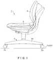
- the present invention relates to an office chair and, in particular, to a chair that can naturally adopt either of two positions, a serious working position and a relaxed reclining position, when a person is seated upon it.
- the typical office chair that has long been used is provided with a gas spring and a coil spring as attached energy means on the underside of a seat thereof, and the configuration is such that large inclinations of a back rest are implemented by the gas spring whereas small adjustments of the inclination of the back rest in the final stages are implemented by the coil spring.
- the present invention was devised in the light of the above described problems and has as an objective the provision of a chair that is inexpensive and has a structure such that it can naturally adopt either a serious working position or a relaxed reclining position, and which is designed to remove the defects of the prior art.
- the present invention concerns a chair in which a base member is fitted onto an upper portion of a leg comprising a plurality of castors in contact with a floor together with support members for these castors, and a seat portion and a back rest are provided on an upper portion of a support plate attached to the base member so as to be is capable of reclining with respect thereto.
- this chair is also provided with a cam-shaped link capable of rotating about the periphery of a pin provided in the base member, an upper portion of the link protrudes towards the support plate side, and a corresponding elastic member that is compressed by the rotation of the link is provided in a bottom portion of the base member.
- a shaft portion in contact with the link, and which causes the link to change profile in response to the reclining action of the support plate, is provided within the support plate.
- a stopper lever is also provided in the base member to maintain the upright state of the link.
- the inclination of the base member causes the shaft portion to compress the link of the base member that it is in contact with, and thus a cushion state can be maintained.
- Operation of the stopper lever holds the link in its upright state, and thus the inclination of the seat portion and back rest of the chair can be locked in a simple manner.
- a base member 3 is fitted onto an upper portion of a leg 2 comprising a plurality of radially arranged castors 2a in contact with a floor together with support members 2b for these castors 2a, and a seat portion 5 and a back rest 6 are provided on a support plate 4 that is capable of reclining with respect to the base member 3.
- the configuration is such that a cam-shaped link 8 wherein its back surface has a cam-shaped surface 8b is rotatably attached around the periphery of a pin 7 that is provided in the base member 3, an upper portion of the link protrudes towards the support plate 4 side, and a corresponding elastic member 9 that is compressed by the rotation of the link 8 is provided in a bottom portion of the base member 3.
- a shaft portion 10 in contact with the link 8, and which causes the link 8 to change profile in response to the reclining action of the support plate 4, is provided within the support plate 4.
- a stopper lever 11 is also provided in the base member 3 to maintain the upright state of the link 8.
- the seat portion 5 and back rest 6 of the chair 1 of the present invention are so designed to be able to be reclined backwards from a solid-line position to a dotted line position shown in Fig. 1, in the same manner as a prior art chair.
- the frame structure of this chair is such that the support plate 4 of the upper portion thereof rotates with respect to the base member 3 about a pivot of a pin 12 affixed to a front portion of the chair, as shown in Fig. 2 and Fig. 3, the back frame 13 rotates about a pivot of the shaft portion 10 provided in the support plate 4, and the base member 3 and back frame 13 are further linked together by a pin 14 that passes through an elongated hole.
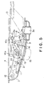
- FIG. 4 A plan view of the structure of Fig. 2 is shown in Fig. 4, and a detailed side view thereof is shown in Fig. 5, illustrating that the base member 3 is within the support plate 4, and the back frame 13 is provided in a rear portion of the base member 3.
- a coil spring 15, the link 8 that is a vital component of the present invention, the elastic member 9 formed of a material such as polyurethane rubber, and a cushion receptacle 16 that holds the elastic member 9 are provided within the base member 3, and a collar 10a is provided straddling over the shaft portion 10 between the wall surfaces of the support plate 4.
- Reference number 3a denotes a hole for inserting the leg 2.
- the stopper lever 11 is provided in a lower portion (on the front left side) of the assembly. In an upper portion (on the front right side) thereof, there is a lever 17 for raising and lowering the chair 1, with a lever cap 18 for raising and lowering the seat portion being provided at a leading end thereof.
- the cam-shaped surface 8b of the link 8 is ordinarily placed in contact with the collar 10a attached to the shaft portion 10, there are projections 8a in the front side thereof at the center and at each end, the pin 7 is inserted into a lower portion thereof, and the upper portion thereof rotates about the pin 7. This ensures that, when the back rest is inclined forward, the projections 8a first come into contact with the elastic member 9 made of a material such as polyurethane rubber and then compress it.
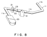
- the stopper lever 11 of the chair in accordance with the present invention shown in perspective in Fig. 8, has a shape such that two end portions 11a and 11b thereof are bent into mutually opposite directions with respect to a central portion 11c thereof, the central portion 11c is supported on a stopper lever stay 19 provided in a base portion of the base member 3 in such a manner that the entire lever can rotate upward or downward.
- the end portion 11a on the outer side is provided with a handle 20.
- a V-shaped notch 16a is provided in an upper portion of the cushion receptacle 16.
- reference number 4a denotes a cutout for preventing the stopper lever 11 from moving upward
- reference number 21 denotes a slide guide
- reference number 22 denotes an elongated hole into which a peg 23 provided on the stopper lever 11 is inserted so that it can move either up or down, for fixing the stopper lever 11 in position.
- the support plate 4 When a person sits on the seat portion 5 with the chair in the state shown in Fig. 5, the support plate 4 reclines backward with respect to the base member 3. This causes the collar 10a that is ordinarily in contact with the cam-shaped surface 8b of the link 8 to be pushed down while sliding over the outer periphery of the link 8, so that the link 8 compresses the forward-inclined elastic member 9 and reaches the state shown in Fig. 6.
- the chair 1 receives a reactive force not only from the coil spring 15 but also from the elastic member 9, and can thus take up a more natural reclining position.
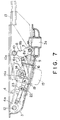
- the user returns the back portion to its foremost inclined position (the state shown in Fig. 5), then operates the end portion 11a of the stopper lever 11 having the handle 20 in the upward direction, as shown by the arrow, so that the other end portion 11b enters the notch 16a of the cushion receptacle 16.
- the stopper lever 11 stops the rotation of the link 8, even if the link 8 has been inclined forward by the person sitting down on the seat portion 5.
- the backward inclination of the seat portion 5 and back rest 6 of the chair 1 is locked.
- the stopper lever 11 is fixed at the upper side of the elongated hole 22. To release the lock, the user can operate the stopper lever 11 in the downward direction.
- a base member is fitted onto an upper portion of a leg comprising a plurality of radially arranged castors in contact with a floor together with support members for these castors, and a seat portion and a back rest are provided on an upper portion of a support plate that is capable of reclining with respect to the base member.
- the chair is also provided with a cam-shaped link capable of rotating about the periphery of a pin provided in the base member, an upper portion of the link protrudes towards the support plate side, and a corresponding elastic member that is compressed by the rotation of the link is provided in a bottom portion of the base member.
- the provision within the support plate of a shaft portion in contact with the link, and which causes the link to change profile in response to the reclining action of the support plate, ensures that the shape of the link can be selected and fabricated as appropriate and the reactive force of the chair can be set to any required level by compression of the elastic member 9 formed of a material such as polyurethane rubber. Therefore, the weight of the user can be supported in a natural manner throughout the entire use of the chair. Since the movement of the link can be stopped by a simple mechanism, the chair's position while the user is working can be maintained, and the working position can be locked.
Landscapes
- Health & Medical Sciences (AREA)
- Dentistry (AREA)
- General Health & Medical Sciences (AREA)
- Chairs For Special Purposes, Such As Reclining Chairs (AREA)
- Chair Legs, Seat Parts, And Backrests (AREA)
- Chairs Characterized By Structure (AREA)
Description
- The present invention relates to an office chair and, in particular, to a chair that can naturally adopt either of two positions, a serious working position and a relaxed reclining position, when a person is seated upon it.
- The typical office chair that has long been used is provided with a gas spring and a coil spring as attached energy means on the underside of a seat thereof, and the configuration is such that large inclinations of a back rest are implemented by the gas spring whereas small adjustments of the inclination of the back rest in the final stages are implemented by the coil spring.
- However, since a gas spring is used as the reclining mechanism for the seat, the manufacturing costs are inevitably high, and thus it is extremely difficult in the prior art to provide an inexpensive chair, despite all efforts to reduce the costs of other components.
- In addition, since adjustment of the seat back reactive force in the prior art makes use of a spring such as a coil spring with a single type of spring characteristic, it is difficult to implement a natural reclining state. In other words, the fault occurs that, just by the person sitting, the seat portion and back rest of the chair recline backwards, making it difficult to achieve a working position, on the other hand, if the reactive force of the coil spring is made stronger, this makes it difficult to recline backwards, and in that state reclining becomes so difficult it is not possible to relax.
- The present invention was devised in the light of the above described problems and has as an objective the provision of a chair that is inexpensive and has a structure such that it can naturally adopt either a serious working position or a relaxed reclining position, and which is designed to remove the defects of the prior art.
- In order to achieve the above objective, the present invention concerns a chair in which a base member is fitted onto an upper portion of a leg comprising a plurality of castors in contact with a floor together with support members for these castors, and a seat portion and a back rest are provided on an upper portion of a support plate attached to the base member so as to be is capable of reclining with respect thereto. In accordance with this invention, this chair is also provided with a cam-shaped link capable of rotating about the periphery of a pin provided in the base member, an upper portion of the link protrudes towards the support plate side, and a corresponding elastic member that is compressed by the rotation of the link is provided in a bottom portion of the base member. A shaft portion in contact with the link, and which causes the link to change profile in response to the reclining action of the support plate, is provided within the support plate. A stopper lever is also provided in the base member to maintain the upright state of the link.
- With the above described configuration, the inclination of the base member causes the shaft portion to compress the link of the base member that it is in contact with, and thus a cushion state can be maintained. Operation of the stopper lever holds the link in its upright state, and thus the inclination of the seat portion and back rest of the chair can be locked in a simple manner.
-
- Fig. 1 is a side view of the exterior of an embodiment of a chair in accordance with the present invention;
- Fig. 2 is a side view of a frame portion of the chair shown in Fig. 1;
- Fig. 3 is a side view of the frame portion of Fig. 2 when it is in a reclined state;
- Fig. 4 is a plan view of the frame portion of Fig. 2;
- Fig. 5 is a side view of an embodiment of vital components of the chair in accordance with the present invention;
- Fig. 6 is a side view of the vital chair components of Fig. 5 when in an inclined state;
- Fig. 7 is a side view of the vital chair components of Fig. 5 in a state when they are locked by a stopper lever; and
- Fig. 8 is a perspective view of the stopper lever.
- An embodiment of the present invention will be described below with reference to the accompanying drawings.
- In a
chair 1 of the present invention, shown in Fig. 1 and Fig. 2, abase member 3 is fitted onto an upper portion of a leg 2 comprising a plurality of radially arrangedcastors 2a in contact with a floor together withsupport members 2b for thesecastors 2a, and aseat portion 5 and aback rest 6 are provided on asupport plate 4 that is capable of reclining with respect to thebase member 3. - As shown in Fig. 4 and Fig. 5, the configuration is such that a cam-
shaped link 8 wherein its back surface has a cam-shaped surface 8b is rotatably attached around the periphery of a pin 7 that is provided in thebase member 3, an upper portion of the link protrudes towards thesupport plate 4 side, and a correspondingelastic member 9 that is compressed by the rotation of thelink 8 is provided in a bottom portion of thebase member 3. Ashaft portion 10 in contact with thelink 8, and which causes thelink 8 to change profile in response to the reclining action of thesupport plate 4, is provided within thesupport plate 4. A stopper lever 11 is also provided in thebase member 3 to maintain the upright state of thelink 8. - The
seat portion 5 andback rest 6 of thechair 1 of the present invention are so designed to be able to be reclined backwards from a solid-line position to a dotted line position shown in Fig. 1, in the same manner as a prior art chair. The frame structure of this chair is such that thesupport plate 4 of the upper portion thereof rotates with respect to thebase member 3 about a pivot of apin 12 affixed to a front portion of the chair, as shown in Fig. 2 and Fig. 3, theback frame 13 rotates about a pivot of theshaft portion 10 provided in thesupport plate 4, and thebase member 3 andback frame 13 are further linked together by apin 14 that passes through an elongated hole. - A plan view of the structure of Fig. 2 is shown in Fig. 4, and a detailed side view thereof is shown in Fig. 5, illustrating that the
base member 3 is within thesupport plate 4, and theback frame 13 is provided in a rear portion of thebase member 3. Acoil spring 15, thelink 8 that is a vital component of the present invention, theelastic member 9 formed of a material such as polyurethane rubber, and acushion receptacle 16 that holds theelastic member 9 are provided within thebase member 3, and acollar 10a is provided straddling over theshaft portion 10 between the wall surfaces of thesupport plate 4.Reference number 3a denotes a hole for inserting the leg 2. As shown in Fig. 5, the stopper lever 11 is provided in a lower portion (on the front left side) of the assembly. In an upper portion (on the front right side) thereof, there is alever 17 for raising and lowering thechair 1, with alever cap 18 for raising and lowering the seat portion being provided at a leading end thereof. - The cam-
shaped surface 8b of thelink 8 is ordinarily placed in contact with thecollar 10a attached to theshaft portion 10, there areprojections 8a in the front side thereof at the center and at each end, the pin 7 is inserted into a lower portion thereof, and the upper portion thereof rotates about the pin 7. This ensures that, when the back rest is inclined forward, theprojections 8a first come into contact with theelastic member 9 made of a material such as polyurethane rubber and then compress it. - The stopper lever 11 of the chair in accordance with the present invention, shown in perspective in Fig. 8, has a shape such that two end portions 11a and 11b thereof are bent into mutually opposite directions with respect to a central portion 11c thereof, the central portion 11c is supported on a stopper lever stay 19 provided in a base portion of the
base member 3 in such a manner that the entire lever can rotate upward or downward. The end portion 11a on the outer side is provided with ahandle 20. A V-shaped notch 16a is provided in an upper portion of thecushion receptacle 16. When the end portion 11b at the inner side of the stopper lever 11 rotates and enters thenotch 16a, it comes into contact with thelink 8 in such a manner that it releases the forward inclination. In Fig. 5,reference number 4a denotes a cutout for preventing the stopper lever 11 from moving upward,reference number 21 denotes a slide guide, andreference number 22 denotes an elongated hole into which apeg 23 provided on the stopper lever 11 is inserted so that it can move either up or down, for fixing the stopper lever 11 in position. - The operation of the chair in accordance with the present invention will now be described.
- When a person sits on the
seat portion 5 with the chair in the state shown in Fig. 5, thesupport plate 4 reclines backward with respect to thebase member 3. This causes thecollar 10a that is ordinarily in contact with the cam-shaped surface 8b of thelink 8 to be pushed down while sliding over the outer periphery of thelink 8, so that thelink 8 compresses the forward-inclinedelastic member 9 and reaches the state shown in Fig. 6. Thus thechair 1 receives a reactive force not only from thecoil spring 15 but also from theelastic member 9, and can thus take up a more natural reclining position. - Next, to change the reclining position shown in Fig. 6 to a working position, the user returns the back portion to its foremost inclined position (the state shown in Fig. 5), then operates the end portion 11a of the stopper lever 11 having the
handle 20 in the upward direction, as shown by the arrow, so that the other end portion 11b enters thenotch 16a of thecushion receptacle 16. Thus the stopper lever 11 stops the rotation of thelink 8, even if thelink 8 has been inclined forward by the person sitting down on theseat portion 5. The backward inclination of theseat portion 5 andback rest 6 of thechair 1 is locked. Then the stopper lever 11 is fixed at the upper side of theelongated hole 22. To release the lock, the user can operate the stopper lever 11 in the downward direction. - As described above, in the chair in accordance with the present invention, a base member is fitted onto an upper portion of a leg comprising a plurality of radially arranged castors in contact with a floor together with support members for these castors, and a seat portion and a back rest are provided on an upper portion of a support plate that is capable of reclining with respect to the base member. The chair is also provided with a cam-shaped link capable of rotating about the periphery of a pin provided in the base member, an upper portion of the link protrudes towards the support plate side, and a corresponding elastic member that is compressed by the rotation of the link is provided in a bottom portion of the base member. The provision within the support plate of a shaft portion in contact with the link, and which causes the link to change profile in response to the reclining action of the support plate, ensures that the shape of the link can be selected and fabricated as appropriate and the reactive force of the chair can be set to any required level by compression of the
elastic member 9 formed of a material such as polyurethane rubber. Therefore, the weight of the user can be supported in a natural manner throughout the entire use of the chair. Since the movement of the link can be stopped by a simple mechanism, the chair's position while the user is working can be maintained, and the working position can be locked.
Claims (5)
- A chair (1) in which a base member (3) is fitted onto an upper portion of a leg (2) which comprises a plurality of castors (2a) in contact with a floor and which supports said castors (2a), and a seat portion (5) and a back rest (6) are provided on an upper portion of a support plate (4) which is capable of reclining with respect to said base member (3), said chair (1) comprising:a cam-shaped link (8)capable of rotating about the periphery of a pin (7) provided in said base member (3), and an upper portion of said link (8) protruding towards said support plate side (4);an elastic member (9) which is compressed by the rotation of said link (8) and which is provided in a bottom portion of said base member (3); anda shaft portion (10) in contact with said link (8), and which causes said link to change profile in response to the reclining action of said support plate (4).
- The chair of claim 1, further comprising a stopper lever (11) for maintaining said (8) link in an upright state within said base member (3).
- The chair of claim 1, wherein projections (8a) are provided at a central portion and end portions of a front side of said link (8), in such a manner that said projections come into contact with and compress said elastic member (9) when said back rest (6) is inclined forward.
- The chair of claim 2, wherein said stopper lever (11) has a shape in which two end portions thereof are bent in mutually opposite directions with respect to a central portion thereof, and one of said end portions is provided with a handle (20).
- The chair of claim 2, further comprising a cushion receptacle (16) provided adjacent to said elastic member (9) and facing said elastic member (9), wherein a V-shaped notch (16a) is formed in an upper portion of said cushion receptacle (16) and, when said stopper lever (11) rotates in such a manner that the inner end portion thereof enters said notch (16a), said stopper lever (11) comes into contact with said link (8) and prevents the forward inclination thereof.
Applications Claiming Priority (3)
| Application Number | Priority Date | Filing Date | Title |
|---|---|---|---|
| JP1993040867U JP2596820Y2 (en) | 1993-07-27 | 1993-07-27 | Chair |
| JP40867/93 | 1993-07-27 | ||
| JP40867/93U | 1993-07-27 |
Publications (2)
| Publication Number | Publication Date |
|---|---|
| EP0636329A1 EP0636329A1 (en) | 1995-02-01 |
| EP0636329B1 true EP0636329B1 (en) | 1996-09-25 |
Family
ID=12592481
Family Applications (1)
| Application Number | Title | Priority Date | Filing Date |
|---|---|---|---|
| EP94305502A Expired - Lifetime EP0636329B1 (en) | 1993-07-27 | 1994-07-26 | Chair |
Country Status (6)
| Country | Link |
|---|---|
| US (1) | US5601337A (en) |
| EP (1) | EP0636329B1 (en) |
| JP (1) | JP2596820Y2 (en) |
| KR (1) | KR0155397B1 (en) |
| DE (1) | DE69400603T2 (en) |
| TW (1) | TW353911U (en) |
Families Citing this family (32)
| Publication number | Priority date | Publication date | Assignee | Title |
|---|---|---|---|---|
| JPS5168483U (en) * | 1974-11-26 | 1976-05-31 | ||
| JPS5168485U (en) * | 1974-11-26 | 1976-05-31 | ||
| JPS5168482U (en) * | 1974-11-26 | 1976-05-31 | ||
| JPS5162583A (en) * | 1974-11-26 | 1976-05-31 | Okamoto Riken Gomu Kk | HYONOKEN MIZUMAKURA |
| JPS5168484U (en) * | 1974-11-26 | 1976-05-31 | ||
| JPS5171695U (en) * | 1974-12-02 | 1976-06-05 | ||
| JPS51102994U (en) * | 1975-02-15 | 1976-08-18 | ||
| IT234647Y1 (en) * | 1994-10-20 | 2000-03-13 | Cofemo Spa | OSCILLATING SUPPORT UNIT FOR CHAIRS WITH SEAT AND BACKREST WITH SYNCHRONIZED VARIABLE INCLINATION |
| JP3719739B2 (en) * | 1995-06-29 | 2005-11-24 | 日本精工株式会社 | Method for manufacturing elastic universal joint yoke |
| US6139103A (en) * | 1997-03-12 | 2000-10-31 | Leggett & Platt, Inc. | Synchronized chair seat and backrest tilt control mechanism |
| GB0010238D0 (en) * | 2000-04-28 | 2000-06-14 | Northeastern Components Intern | Locking mechanism for chair and pushbutton control therefor |
| US6523900B1 (en) | 2000-09-01 | 2003-02-25 | Irwin Seating Company | Chair seat |
| GB0024840D0 (en) * | 2000-10-10 | 2000-11-22 | Rodd Engineering Ltd | Chair tilting mechanism and a chair incorporating such a mechanism |
| DE10200355A1 (en) * | 2002-01-08 | 2003-07-17 | Dauphin Friedrich W Gmbh | chair |
| EP1527714B1 (en) * | 2002-07-23 | 2008-11-26 | Okamura corporation | Chair |
| US7147285B2 (en) * | 2004-01-20 | 2006-12-12 | Tung Yu Oa Co., Ltd. | Reclining apparatus for chair |
| USD528328S1 (en) * | 2004-04-08 | 2006-09-19 | Ergo-Industrial Seating Systems Ltd. | Shaped levers |
| KR100678653B1 (en) * | 2005-05-16 | 2007-02-05 | 기 석 우 | Multifunctional chair |
| US7837265B2 (en) * | 2006-03-24 | 2010-11-23 | Hni Corporation | Reclining chair with enhanced adjustability |
| US8251448B2 (en) | 2007-03-13 | 2012-08-28 | Hni Technologies Inc. | Dynamic chair back lumbar support system |
| JP5460998B2 (en) * | 2008-10-20 | 2014-04-02 | タカノ株式会社 | Locking mechanism of the locking device |
| US8002351B2 (en) | 2009-01-26 | 2011-08-23 | Knoll, Inc. | Support member |
| US9284729B2 (en) | 2010-05-05 | 2016-03-15 | Allsteel Inc. | Modular wall system |
| US8616640B2 (en) | 2010-05-20 | 2013-12-31 | Knoll, Inc. | Chair |
| IT1403471B1 (en) * | 2010-12-03 | 2013-10-17 | Imarc Spa | MECHANISM FOR OFFICE CHAIRS PROVIDED WITH A SWINGING FORCE ADJUSTMENT DEVICE. |
| WO2014144143A1 (en) | 2013-03-15 | 2014-09-18 | Hni Technologies Inc. | Chair with activated back flex |
| USD731833S1 (en) | 2014-04-17 | 2015-06-16 | Allsteel Inc. | Chair |
| WO2015160693A1 (en) | 2014-04-17 | 2015-10-22 | Hni Technologies Inc. | Flex lumbar support |
| US9801470B2 (en) | 2014-10-15 | 2017-10-31 | Hni Technologies Inc. | Molded chair with integrated support and method of making same |
| USD743180S1 (en) | 2014-10-15 | 2015-11-17 | Hni Technologies Inc. | Chair |
| TWI685317B (en) * | 2016-10-07 | 2020-02-21 | 堡勝企業股份有限公司 | Chair back cushion adjustment device and chair with chair back cushion adjustment device |
| IT201600118868A1 (en) * | 2016-11-25 | 2018-05-25 | Oscar Bessega | Oscillating mechanism for seats |
Family Cites Families (7)
| Publication number | Priority date | Publication date | Assignee | Title |
|---|---|---|---|---|
| US2447601A (en) * | 1946-02-19 | 1948-08-24 | Sikes Company | Tilting chair seat and back rest |
| US3417956A (en) * | 1966-08-02 | 1968-12-24 | Art Metal Knoll Corp | Chair control |
| US3627252A (en) * | 1969-12-22 | 1971-12-14 | Yoshiomi Yamaguchi | Tilting chair |
| DE3724582A1 (en) * | 1987-07-24 | 1989-02-02 | Inaba Seisakusho Ltd | A piece of seating furniture |
| CH675817A5 (en) * | 1988-04-07 | 1990-11-15 | Giroflex Entwicklungs Ag | |
| IT1236439B (en) * | 1989-12-14 | 1993-03-01 | Loris Miotto | Movement device for chair |
| DE9104854U1 (en) * | 1991-04-20 | 1991-06-06 | Bürositzmöbelfabrik Friedrich-W. Dauphin GmbH & Co, 8561 Offenhausen | Chair, especially office chair |
-
1993
- 1993-07-27 JP JP1993040867U patent/JP2596820Y2/en not_active Expired - Fee Related
-
1994
- 1994-07-21 US US08/278,259 patent/US5601337A/en not_active Expired - Lifetime
- 1994-07-26 EP EP94305502A patent/EP0636329B1/en not_active Expired - Lifetime
- 1994-07-26 DE DE69400603T patent/DE69400603T2/en not_active Expired - Fee Related
- 1994-07-26 KR KR1019940018060A patent/KR0155397B1/en not_active Expired - Fee Related
- 1994-07-26 TW TW086210729U patent/TW353911U/en unknown
Also Published As
| Publication number | Publication date |
|---|---|
| JPH079143U (en) | 1995-02-10 |
| DE69400603T2 (en) | 1997-04-17 |
| DE69400603D1 (en) | 1996-10-31 |
| EP0636329A1 (en) | 1995-02-01 |
| KR950002673A (en) | 1995-02-16 |
| KR0155397B1 (en) | 1998-11-16 |
| JP2596820Y2 (en) | 1999-06-21 |
| US5601337A (en) | 1997-02-11 |
| TW353911U (en) | 1999-03-01 |
Similar Documents
| Publication | Publication Date | Title |
|---|---|---|
| EP0636329B1 (en) | Chair | |
| US6733071B2 (en) | Self-locking rocker recliner chair | |
| EP0517206B1 (en) | Chair control mechanism | |
| JP2003521956A (en) | Chair mechanism | |
| EP1192877B1 (en) | A reclinable chair | |
| CN100401945C (en) | Improved Ergonomic Seat | |
| US5683139A (en) | Chair seat tilt adjustment and locking mechanism | |
| EP0614633B1 (en) | Adjustbale backrest for a chair | |
| GB2293971A (en) | Seating furniture | |
| JPH0523079Y2 (en) | ||
| EP0466777A1 (en) | Ergonomic chair | |
| GB2414391A (en) | Adjustable chair having inclining backrest and seat squab pivotally linked to a tilt housing | |
| WO1994029140A1 (en) | Pivotable and height-adjustable chair back rest assembly and blow-molded back rest therefor | |
| US10743667B2 (en) | Chair back tilt mechanism | |
| WO2002032260A1 (en) | Armchair with variable position | |
| JP2002527175A (en) | Chair adjustment mechanism, back cover and armrest | |
| EP0160017A1 (en) | Improved back support means. | |
| US20090146468A1 (en) | Reclining Lounge Chair | |
| US5259663A (en) | Chair seat mounting mechanism | |
| US5417474A (en) | Tilt control mechanism for chairs | |
| WO2008049435A1 (en) | A synchronizing device for an office chair | |
| WO1990002502A1 (en) | Locking mechanism for a foldable piece of seating furniture | |
| CN113080643A (en) | Leisure chair | |
| CN218419065U (en) | Self-adaptive linkage control functional single chair | |
| EP0954997B1 (en) | Device for the synchronized adjustment of the position of the seat and back of a chair |
Legal Events
| Date | Code | Title | Description |
|---|---|---|---|
| PUAI | Public reference made under article 153(3) epc to a published international application that has entered the european phase |
Free format text: ORIGINAL CODE: 0009012 |
|
| AK | Designated contracting states |
Kind code of ref document: A1 Designated state(s): DE FR GB IT |
|
| 17P | Request for examination filed |
Effective date: 19950209 |
|
| GRAG | Despatch of communication of intention to grant |
Free format text: ORIGINAL CODE: EPIDOS AGRA |
|
| 17Q | First examination report despatched |
Effective date: 19951215 |
|
| GRAH | Despatch of communication of intention to grant a patent |
Free format text: ORIGINAL CODE: EPIDOS IGRA |
|
| GRAH | Despatch of communication of intention to grant a patent |
Free format text: ORIGINAL CODE: EPIDOS IGRA |
|
| GRAA | (expected) grant |
Free format text: ORIGINAL CODE: 0009210 |
|
| AK | Designated contracting states |
Kind code of ref document: B1 Designated state(s): DE FR GB IT |
|
| REF | Corresponds to: |
Ref document number: 69400603 Country of ref document: DE Date of ref document: 19961031 |
|
| ITF | It: translation for a ep patent filed | ||
| ET | Fr: translation filed | ||
| PLBE | No opposition filed within time limit |
Free format text: ORIGINAL CODE: 0009261 |
|
| STAA | Information on the status of an ep patent application or granted ep patent |
Free format text: STATUS: NO OPPOSITION FILED WITHIN TIME LIMIT |
|
| 26N | No opposition filed | ||
| REG | Reference to a national code |
Ref country code: GB Ref legal event code: IF02 |
|
| PGFP | Annual fee paid to national office [announced via postgrant information from national office to epo] |
Ref country code: FR Payment date: 20060612 Year of fee payment: 13 |
|
| PGFP | Annual fee paid to national office [announced via postgrant information from national office to epo] |
Ref country code: DE Payment date: 20060720 Year of fee payment: 13 |
|
| PGFP | Annual fee paid to national office [announced via postgrant information from national office to epo] |
Ref country code: GB Payment date: 20060726 Year of fee payment: 13 |
|
| PGFP | Annual fee paid to national office [announced via postgrant information from national office to epo] |
Ref country code: IT Payment date: 20060731 Year of fee payment: 13 |
|
| GBPC | Gb: european patent ceased through non-payment of renewal fee |
Effective date: 20070726 |
|
| PG25 | Lapsed in a contracting state [announced via postgrant information from national office to epo] |
Ref country code: DE Free format text: LAPSE BECAUSE OF NON-PAYMENT OF DUE FEES Effective date: 20080201 |
|
| PG25 | Lapsed in a contracting state [announced via postgrant information from national office to epo] |
Ref country code: GB Free format text: LAPSE BECAUSE OF NON-PAYMENT OF DUE FEES Effective date: 20070726 |
|
| REG | Reference to a national code |
Ref country code: FR Ref legal event code: ST Effective date: 20080331 |
|
| PG25 | Lapsed in a contracting state [announced via postgrant information from national office to epo] |
Ref country code: FR Free format text: LAPSE BECAUSE OF NON-PAYMENT OF DUE FEES Effective date: 20070731 |
|
| PG25 | Lapsed in a contracting state [announced via postgrant information from national office to epo] |
Ref country code: IT Free format text: LAPSE BECAUSE OF NON-PAYMENT OF DUE FEES Effective date: 20070726 |