EP0635247B1 - Elbow lifting device - Google Patents
Elbow lifting device Download PDFInfo
- Publication number
- EP0635247B1 EP0635247B1 EP94105939A EP94105939A EP0635247B1 EP 0635247 B1 EP0635247 B1 EP 0635247B1 EP 94105939 A EP94105939 A EP 94105939A EP 94105939 A EP94105939 A EP 94105939A EP 0635247 B1 EP0635247 B1 EP 0635247B1
- Authority
- EP
- European Patent Office
- Prior art keywords
- elbow
- forearm
- lifter according
- mating part
- arm
- Prior art date
- Legal status (The legal status is an assumption and is not a legal conclusion. Google has not performed a legal analysis and makes no representation as to the accuracy of the status listed.)
- Expired - Lifetime
Links
- 210000000245 forearm Anatomy 0.000 claims abstract description 41
- 238000005452 bending Methods 0.000 claims abstract description 11
- 238000000034 method Methods 0.000 claims abstract description 6
- 238000010276 construction Methods 0.000 claims description 4
- 230000015572 biosynthetic process Effects 0.000 claims description 2
- 238000013016 damping Methods 0.000 claims description 2
- 230000013011 mating Effects 0.000 claims 11
- 230000005540 biological transmission Effects 0.000 description 10
- 230000007423 decrease Effects 0.000 description 1
- 230000001419 dependent effect Effects 0.000 description 1
- 239000013013 elastic material Substances 0.000 description 1
- 230000005484 gravity Effects 0.000 description 1
- 210000000056 organ Anatomy 0.000 description 1
- 238000004904 shortening Methods 0.000 description 1
Images


Classifications
-
- A—HUMAN NECESSITIES
- A61—MEDICAL OR VETERINARY SCIENCE; HYGIENE
- A61F—FILTERS IMPLANTABLE INTO BLOOD VESSELS; PROSTHESES; DEVICES PROVIDING PATENCY TO, OR PREVENTING COLLAPSING OF, TUBULAR STRUCTURES OF THE BODY, e.g. STENTS; ORTHOPAEDIC, NURSING OR CONTRACEPTIVE DEVICES; FOMENTATION; TREATMENT OR PROTECTION OF EYES OR EARS; BANDAGES, DRESSINGS OR ABSORBENT PADS; FIRST-AID KITS
- A61F2/00—Filters implantable into blood vessels; Prostheses, i.e. artificial substitutes or replacements for parts of the body; Appliances for connecting them with the body; Devices providing patency to, or preventing collapsing of, tubular structures of the body, e.g. stents
- A61F2/50—Prostheses not implantable in the body
- A61F2/54—Artificial arms or hands or parts thereof
- A61F2/58—Elbows; Wrists ; Other joints; Hands
- A61F2/582—Elbow joints
-
- A—HUMAN NECESSITIES
- A61—MEDICAL OR VETERINARY SCIENCE; HYGIENE
- A61F—FILTERS IMPLANTABLE INTO BLOOD VESSELS; PROSTHESES; DEVICES PROVIDING PATENCY TO, OR PREVENTING COLLAPSING OF, TUBULAR STRUCTURES OF THE BODY, e.g. STENTS; ORTHOPAEDIC, NURSING OR CONTRACEPTIVE DEVICES; FOMENTATION; TREATMENT OR PROTECTION OF EYES OR EARS; BANDAGES, DRESSINGS OR ABSORBENT PADS; FIRST-AID KITS
- A61F2/00—Filters implantable into blood vessels; Prostheses, i.e. artificial substitutes or replacements for parts of the body; Appliances for connecting them with the body; Devices providing patency to, or preventing collapsing of, tubular structures of the body, e.g. stents
- A61F2/50—Prostheses not implantable in the body
- A61F2/68—Operating or control means
-
- A—HUMAN NECESSITIES
- A61—MEDICAL OR VETERINARY SCIENCE; HYGIENE
- A61F—FILTERS IMPLANTABLE INTO BLOOD VESSELS; PROSTHESES; DEVICES PROVIDING PATENCY TO, OR PREVENTING COLLAPSING OF, TUBULAR STRUCTURES OF THE BODY, e.g. STENTS; ORTHOPAEDIC, NURSING OR CONTRACEPTIVE DEVICES; FOMENTATION; TREATMENT OR PROTECTION OF EYES OR EARS; BANDAGES, DRESSINGS OR ABSORBENT PADS; FIRST-AID KITS
- A61F2/00—Filters implantable into blood vessels; Prostheses, i.e. artificial substitutes or replacements for parts of the body; Appliances for connecting them with the body; Devices providing patency to, or preventing collapsing of, tubular structures of the body, e.g. stents
- A61F2/50—Prostheses not implantable in the body
- A61F2/76—Means for assembling, fitting or testing prostheses, e.g. for measuring or balancing, e.g. alignment means
-
- A—HUMAN NECESSITIES
- A61—MEDICAL OR VETERINARY SCIENCE; HYGIENE
- A61F—FILTERS IMPLANTABLE INTO BLOOD VESSELS; PROSTHESES; DEVICES PROVIDING PATENCY TO, OR PREVENTING COLLAPSING OF, TUBULAR STRUCTURES OF THE BODY, e.g. STENTS; ORTHOPAEDIC, NURSING OR CONTRACEPTIVE DEVICES; FOMENTATION; TREATMENT OR PROTECTION OF EYES OR EARS; BANDAGES, DRESSINGS OR ABSORBENT PADS; FIRST-AID KITS
- A61F2/00—Filters implantable into blood vessels; Prostheses, i.e. artificial substitutes or replacements for parts of the body; Appliances for connecting them with the body; Devices providing patency to, or preventing collapsing of, tubular structures of the body, e.g. stents
- A61F2/50—Prostheses not implantable in the body
- A61F2/68—Operating or control means
- A61F2/70—Operating or control means electrical
-
- A—HUMAN NECESSITIES
- A61—MEDICAL OR VETERINARY SCIENCE; HYGIENE
- A61F—FILTERS IMPLANTABLE INTO BLOOD VESSELS; PROSTHESES; DEVICES PROVIDING PATENCY TO, OR PREVENTING COLLAPSING OF, TUBULAR STRUCTURES OF THE BODY, e.g. STENTS; ORTHOPAEDIC, NURSING OR CONTRACEPTIVE DEVICES; FOMENTATION; TREATMENT OR PROTECTION OF EYES OR EARS; BANDAGES, DRESSINGS OR ABSORBENT PADS; FIRST-AID KITS
- A61F2/00—Filters implantable into blood vessels; Prostheses, i.e. artificial substitutes or replacements for parts of the body; Appliances for connecting them with the body; Devices providing patency to, or preventing collapsing of, tubular structures of the body, e.g. stents
- A61F2/50—Prostheses not implantable in the body
- A61F2002/5007—Prostheses not implantable in the body having elastic means different from springs, e.g. including an elastomeric insert
-
- A—HUMAN NECESSITIES
- A61—MEDICAL OR VETERINARY SCIENCE; HYGIENE
- A61F—FILTERS IMPLANTABLE INTO BLOOD VESSELS; PROSTHESES; DEVICES PROVIDING PATENCY TO, OR PREVENTING COLLAPSING OF, TUBULAR STRUCTURES OF THE BODY, e.g. STENTS; ORTHOPAEDIC, NURSING OR CONTRACEPTIVE DEVICES; FOMENTATION; TREATMENT OR PROTECTION OF EYES OR EARS; BANDAGES, DRESSINGS OR ABSORBENT PADS; FIRST-AID KITS
- A61F2/00—Filters implantable into blood vessels; Prostheses, i.e. artificial substitutes or replacements for parts of the body; Appliances for connecting them with the body; Devices providing patency to, or preventing collapsing of, tubular structures of the body, e.g. stents
- A61F2/50—Prostheses not implantable in the body
- A61F2002/5072—Prostheses not implantable in the body having spring elements
- A61F2002/5078—2-D spiral springs
-
- A—HUMAN NECESSITIES
- A61—MEDICAL OR VETERINARY SCIENCE; HYGIENE
- A61F—FILTERS IMPLANTABLE INTO BLOOD VESSELS; PROSTHESES; DEVICES PROVIDING PATENCY TO, OR PREVENTING COLLAPSING OF, TUBULAR STRUCTURES OF THE BODY, e.g. STENTS; ORTHOPAEDIC, NURSING OR CONTRACEPTIVE DEVICES; FOMENTATION; TREATMENT OR PROTECTION OF EYES OR EARS; BANDAGES, DRESSINGS OR ABSORBENT PADS; FIRST-AID KITS
- A61F2/00—Filters implantable into blood vessels; Prostheses, i.e. artificial substitutes or replacements for parts of the body; Appliances for connecting them with the body; Devices providing patency to, or preventing collapsing of, tubular structures of the body, e.g. stents
- A61F2/50—Prostheses not implantable in the body
- A61F2/68—Operating or control means
- A61F2002/6854—Operating or control means for locking or unlocking a joint
Definitions
- the invention relates to a method for applying a Torque on the elbow axis of an upper arm prosthesis Swiveling the forearm with the help of a spring force.
- the invention further relates to an elbow lifter for an arm prosthesis, whose upper arm fitting part over at least one elbow axis is articulated to a forearm fitting part, the pivoting thereof supported by a spring element of the elbow lifter becomes.
- US-A-2,626,398 discloses an elbow lifter which is designed as in the elastic elbow axis integrated, tensionable spring element is that concentrically overlapping the elbow axis Hollow shaft acted on with the forearm fitting part Rails is rotatably connected.
- One is also planned manually operated cantilever phase. Otherwise, however, this shows Elbow lifters also have the disadvantages mentioned above on.
- the invention is therefore based on the object of a method and to develop an elbow lifter with which the Let the aforementioned shortcomings be avoided.
- This task is based on the method described above solved according to the invention in that the torque curve depending on the flexion angle of the forearm essentially is parabolic and its lowest values in the Stretch position of essentially 5 ° to 25 °, preferably 10 ° to 20 ° and at maximum diffraction and its maximum at about 90 ° having.
- the stated task is based on the one described at the beginning Elbow lifter solved according to the invention by a gear, its input directly from the spring element with a tensile force or is acted upon indirectly, and its output on the inner End of one with an inner and an outer end Geborgangs attacks, the outer end of one with the Elbow axis a fixed point defining the torque lever Upper arm fitting part can be determined, the power transmission through the transmission takes place so that the course of the at the fixed point of the Upper arm fitting attacking torque depending on Diffraction angle of the forearm fitting part is essentially parabolic is and its lowest values in the stretched position of essentially 5 ° to 25 °, preferably 10 ° to 20 ° and at maximum Diffraction and has its maximum at about 90 °.
- a torque curve is achieved according to the invention, of the exact needs of the support corresponds to the flexion of the forearm. It can be if the system is correctly adjusted, the swing phase of the upper arm stump for advancing and lowering the forearm. This can even be used to control the Forearm required pull rope is eliminated, making a larger one The amputee's freedom of movement is made possible.
- the spring force by an electrical adjustment depending on the bending angle and the torque curve changed and / or by an electrically applied, additional torque is amplified.
- Device-wise can it be advantageous if the adjustment of the spring element is over a first motor controlled by a sensor takes place.
- an additional torque on the forearm fitting applying motor is provided.
- the spring element is preferably a spiral spring, but could also a tension spring or a similar storage element be.
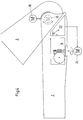
- the arm prosthesis shown in Figure 1 includes an upper arm fitting 1 and a forearm fitting part 2, which has an elbow axis 3 are hinged together.
- an elbow lifter 4 is provided for support the pivoting of the forearm fitting part 2 into different flexion positions. This points a housing that accommodates or encloses all of its components 5 on that in an adapted recess in the forearm fitting 2 is inserted.
- the elbow lifter 4 shown in Figure 2 essentially comprises a coil spring 6, a cam gear 7, a the force from the spiral spring 6 on the cam mechanism 7 transmitting, designed as a flexible elastic belt 8 Power transmission element and a cam gear 7 kinematic connecting element with the upper arm fitting part 1 9.
- the cam gear 7 comprises two cams 7a and 7b, each of which is non-rotatably seated on a common shaft 10.
- the spiral spring 6 is fastened in a spring housing 11 and acts as a rotational force on a driven pulley 12 which an axis 13 sits.
- the bias of the coil spring 6 can corresponding to the to be compensated, attacking the forearm fitting part 2 Weight can be changed by twisting a worm wheel 14, one for actuating it from the outside accessible, manually operated turntable 15, a knurled wheel or the like is provided.
- the belt 8 is at one end at a fixed point 16 attached to the driven pulley 12, wraps around almost completely the outer curve contour of the first cam 7a and is with its other end on the outer circumference of this first cam 7a attached via a fixed point 17, the transmission input of the cam mechanism 7 defined.
- the flexible tension member 9 is at its inner end to the transmission output defining fixed point 18 on the circumference of the second cam 7b attached, is then mounted around a housing 5 Deflection roller 19 guided and is with its outer, from the Housing 5 led out at one end with the elbow axis 3 a fixed point 20 defining the torque arm of the upper arm fitting part 1 set.
- Figure 2 shows that the Tension element 9 with the forearm fitting part 2 extended, the outer curve contour the second cam 7b only over a short Section wraps around and in the area between the pulley 19 and the fixed point 20 on the upper arm fitting part 1 on its lower, contour 21 is approximately circular segment-shaped.
- Figure 3 shows the forearm fitting part 2 in its maximum flexion angle.
- a comparison with Figure 2 makes it clear that starting from the extended arm position with increasing flexion angle of the forearm fitting part 2 with respect to the upper arm fitting part 1 of the straps 8 off the first cam 7a and on that of the Coil spring 6 driven driven pulley 12 wound is, while the traction element 9 increasingly from the lower Contour 21 of the upper arm fitting part 1 releases and onto the second cam 7b is wound up.
- Figure 3 also shows that the guide roller 19 is arranged such that the traction element 9 is brought up to the contour 21 approximately tangentially.
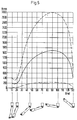
- the transmission 7 is in connection with the characteristic of Spring element 6 designed so that the course of the on Elbow axis 3 applied torque depending on Bending angle of the forearm fitting part 2 approximately parabolic is (see Figure 5) and its lowest values in the stretched position from about 10 ° to 20 ° and at maximum diffraction and Maximum at about 90 °.
- This is done with that in the figures 2 and 3 illustrated embodiments by a corresponding design of the curve of the two cams 7a, 7b, and by their association with one another, thus also a corresponding compensation of the spring force characteristic is made.
- the adjustable range this compensation are shown in FIG. 5 above the flexion angle of the forearm fitting part 2 applied torque lines.
- Figure 4 is indicated schematically that the adjustment of the Spring element 6 also via a first sensor 23 depending on the flexion controlled motor 24 can. This can be done by an electrical adjustment the spring force depending on the bending angle and the Change the torque curve.
- an additional torque provided on the forearm fitting part 2 motor 25 be. This allows the spring force to be increased electrically.
- a third motor 26 is indicated in FIG. 4, with which an electrical locking of the forearm fitting part 2 can be reached in a desired flexion position.
- a comparable one with that through the two cams 7a, 7b achieved kinematics by appropriate curve formation the driven pulley 12, the deflection roller 19 and / or achieve the contour 21.
Landscapes
- Health & Medical Sciences (AREA)
- Transplantation (AREA)
- Vascular Medicine (AREA)
- Life Sciences & Earth Sciences (AREA)
- Oral & Maxillofacial Surgery (AREA)
- Engineering & Computer Science (AREA)
- Biomedical Technology (AREA)
- Heart & Thoracic Surgery (AREA)
- Veterinary Medicine (AREA)
- Cardiology (AREA)
- Animal Behavior & Ethology (AREA)
- General Health & Medical Sciences (AREA)
- Public Health (AREA)
- Orthopedic Medicine & Surgery (AREA)
- Prostheses (AREA)
- Manipulator (AREA)
- Valve-Gear Or Valve Arrangements (AREA)
- Orthopedics, Nursing, And Contraception (AREA)
Abstract
Description
Die Erfindung betrifft ein Verfahren zum Aufbringen eines Drehmomentes auf die Ellbogenachse einer Oberarmprothese zur Verschwenkung des Unterarmes mit Hilfe einer Federkraft.The invention relates to a method for applying a Torque on the elbow axis of an upper arm prosthesis Swiveling the forearm with the help of a spring force.
Die Erfindung betrifft ferner einen Ellbogenlifter für eine Armprothese, deren Oberarmpaßteil über zumindest eine Ellbogenachse gelenkig mit einem Unterarmpaßteil verbunden ist, dessen Verschwenkung durch ein Federelement des Ellbogenlifters unterstützt wird.The invention further relates to an elbow lifter for an arm prosthesis, whose upper arm fitting part over at least one elbow axis is articulated to a forearm fitting part, the pivoting thereof supported by a spring element of the elbow lifter becomes.
Im Prothesenbau wird je nach Leistungsvermögen unterschieden zwischen aktiven und passiven Prothesen. Zur Gruppe der aktiven Prothesen zählen jene, die mit Eigenkraft oder mit Fremdkraft gesteuert werden. Dabei nimmt unter den Eigenkraft-Prothesen die Armprothese mit Kraftzug einen hervorragenden Platz ein. Der Arm mit dem Greiforgan Hand wird schwerkraftbedingt überwiegend auf Zug beansprucht. Deshalb muß nach konstruktiven Lösungen gesucht werden, die zu einer Zugentlastung führen. Bei der aktiven Armprothese wird das willkürliche Beugen des Unterarmes mittels Schulterbandagen aus elastischem Material in Bowdenzügen eingeleitet. Dies geschieht durch Verkürzen des Beugezuges, wobei die Befestigung zwischen Ober- und Unterarm an einem Ende des Zuges erfolgt, und die Kraft über die Schulter zum Oberarm des anderen Zuges eingeleitet wird.In prosthesis construction, a distinction is made according to performance between active and passive prostheses. To the group of active Prostheses count those with their own strength or with external strength being controlled. Thereby takes under the self-strength prostheses Arm prosthesis with power pull an excellent place. The arm with the gripping organ, the hand is mostly open due to gravity Train claimed. Therefore, constructive solutions must be sought that lead to strain relief. With the active prosthetic arm is the arbitrary bending of the forearm by means of Shoulder bandages made of elastic material introduced into Bowden cables. This is done by shortening the flexion, the Attachment between the upper and lower arm at one end of the train and the force over the shoulder to the other's upper arm Train is initiated.
Diese Prothesensysteme haben den Nachteil, daß durch fehlende Kompensation des Gewichtes des Unterarmes eine Ermüdung des Prothesenträgers eintritt; außerdem kann der Beugefunktionsbereich nicht optimal genutzt werden. Zur Kompensation des Gewichtes des Unterarmes wurden verschiedene technische Lösungen entwickelt. Die gebräuchlichsten eingesetzten Konstruktionen sind federunterstützende Systeme, die nahe dem Gelenkpunkt angebracht werden. Der Nachteil dieser Konstruktionen besteht darin, daß das höchste Drehmoment zur Unterstützung der Beugebewegung in der Strecklage des Unterarmes eingeleitet wird, und daß dieses Drehmoment bei der Beugung des Unteramres abnimmt. Der Drehmomentenverlauf ist somit genau entgegengesetzt den tatsächlichen Bedürfnissen. Ein weiterer Nachteil dieser vorbekannten Lösungen ist darin zu sehen, daß bei zu starker Erhöhung des Drehmomentes die Freischwingphase behindert und somit das natürliche Erscheinungsbild mit der Pendelphase des Unterarmes gestört wird.These prosthesis systems have the disadvantage that they are missing Compensation for the weight of the forearm fatigue of the prosthesis wearer entry; also the flexor function area not be used optimally. To compensate for the weight of the Various technical solutions were developed for the forearm. The most common constructions used are spring-supporting Systems that are attached near the hinge point. The disadvantage of these designs is that highest torque to support the flexion movement in the Stretch position of the forearm is initiated, and that this torque decreases when the lower arm is flexed. The torque curve is therefore exactly opposite to the actual needs. Another disadvantage of these previously known solutions can be seen in that if the torque is increased too much the cantilever phase hinders and thus the natural appearance is disturbed with the pendulum phase of the forearm.
Die US-A-2,626,398 offenbart einen Ellbogenlifter, der als in die Ellbogenachse integriertes, spannbares Federelement ausgebildet ist, das eine die Ellbogenachse konzentrisch übergreifende Hohlwelle beaufschlagt, die mit dem Unterarmpaßteil über Schienen drehfest verbunden ist. Vorgesehen ist überdies eine manuell betätigbare Freischwingphase. Im übrigen aber weist dieser Ellbogenlifter ebenfalls die vorstehend genannten Nachteile auf.US-A-2,626,398 discloses an elbow lifter which is designed as in the elastic elbow axis integrated, tensionable spring element is that concentrically overlapping the elbow axis Hollow shaft acted on with the forearm fitting part Rails is rotatably connected. One is also planned manually operated cantilever phase. Otherwise, however, this shows Elbow lifters also have the disadvantages mentioned above on.
Der Erfindung liegt somit die Aufgabe zugrunde, ein Verfahren sowie einen Ellbogenlifter zu entwickeln, mit denen sich die vorgenannten Unzulänglichkeiten vermeiden lassen.The invention is therefore based on the object of a method and to develop an elbow lifter with which the Let the aforementioned shortcomings be avoided.
Diese Aufgabe wird ausgehend von dem eingangs beschriebenen Verfahren erfindungsgemäß dadurch gelöst, daß der Drehmomentenverlauf in Abhängigkeit vom Beugewinkel des Unterarmes im wesentlichen parabelförmig ist und seine niedrigsten Werte in der Strecklage von im wesentlichen 5° bis 25°, vorzugsweise 10° bis 20° sowie bei maximaler Beugung und sein Maximum bei etwa 90° aufweist.This task is based on the method described above solved according to the invention in that the torque curve depending on the flexion angle of the forearm essentially is parabolic and its lowest values in the Stretch position of essentially 5 ° to 25 °, preferably 10 ° to 20 ° and at maximum diffraction and its maximum at about 90 ° having.
Die genannte Aufgabe wird ausgehend von dem eingangs beschriebenen Ellbogenlifter erfindungsgemäß gelöst durch ein Getriebe, dessen Eingang von dem Federelement mit einer Zugkraft direkt oder indirekt beaufschlagt wird, und dessen Ausgang an dem inneren Ende eines mit einem inneren und einem äußeren Ende versehenen Zugorgangs angreift, dessen äußeres Ende an einem mit der Ellbogenachse einen Drehmomenthebel definierenden Fixpunkt des Oberarmpaßteils festlegbar ist, wobei die Kraftübertragung durch das Getriebe so erfolgt, daß der Verlauf des am Fixpunkt des Oberarmpaßteiles angreifenden Drehmomentes in Abhängigkeit vom Beugewinkel des Unterarmpaßteils im wesentlichen parabelförmig ist und seine niedrigsten Werte in der Strecklage von im wesentlichen 5° bis 25°, vorzugsweise 10° bis 20° sowie bei maximaler Beugung und sein Maximum bei etwa 90° aufweist.The stated task is based on the one described at the beginning Elbow lifter solved according to the invention by a gear, its input directly from the spring element with a tensile force or is acted upon indirectly, and its output on the inner End of one with an inner and an outer end Zugorgangs attacks, the outer end of one with the Elbow axis a fixed point defining the torque lever Upper arm fitting part can be determined, the power transmission through the transmission takes place so that the course of the at the fixed point of the Upper arm fitting attacking torque depending on Diffraction angle of the forearm fitting part is essentially parabolic is and its lowest values in the stretched position of essentially 5 ° to 25 °, preferably 10 ° to 20 ° and at maximum Diffraction and has its maximum at about 90 °.
Während also der Drehmomentenverlauf bei den vorbekannten Ellbogenliftern ausgehend von der Strecklage des Armes bis zum maximalen Beugewinkel des Unterarmes von einem Maximum nahezu linear abfällt, wird erfindungsgemäß ein Drehmomentenverlauf erzielt, der exakt den tatsächlichen Bedürnissen bei der Unterstützung der Beugung des Unterarmes entspricht. Dabei läßt sich bei richtiger Anpassung des Systems die Schwungphase des Oberarmstumpfes für das Vorbringen und Absenken des Unterarmes ausnutzen. Hierdurch kann sogar ein sonst für die Steuerung des Unterarmes erforderliches Zugseil entfallen, wodurch eine größere Bewegungsfreiheit des Amputierten ermöglicht wird.So during the torque curve with the known elbow lifters starting from the extended position of the arm to the maximum Flexion angle of the forearm from a maximum almost linear drops, a torque curve is achieved according to the invention, of the exact needs of the support corresponds to the flexion of the forearm. It can be if the system is correctly adjusted, the swing phase of the upper arm stump for advancing and lowering the forearm. This can even be used to control the Forearm required pull rope is eliminated, making a larger one The amputee's freedom of movement is made possible.
In einer Weiterentwicklung des erfinderischen Konzeptes kann es zweckmäßig sein, wenn die Federkraft durch eine elektrische Verstellung in Abhängigkeit vom Beugewinkel sowie des Drehmomentenverlaufes verändert und/oder durch ein elektrisch aufgebrachtes, zusätzliches Drehmoment verstärkt wird. Vorrichtungsmäßig kann es vorteilhaft sein, wenn die Justierung des Federelementes über einen ersten, von einem Sensor gesteuerten Motor erfolgt. Zusätzlich kann es vorteilhaft sein, wenn im Bereich der Ellbogenachse ein zweiter, ein zusätzliches Drehmoment auf das Unterarmpaßteil aufbringender Motor vorgesehen ist.In a further development of the inventive concept, it can be useful if the spring force by an electrical adjustment depending on the bending angle and the torque curve changed and / or by an electrically applied, additional torque is amplified. Device-wise can it be advantageous if the adjustment of the spring element is over a first motor controlled by a sensor takes place. In addition it can be advantageous if in the area of the elbow axis a second, an additional torque on the forearm fitting applying motor is provided.
Es ist vorteilhaft, wenn das Federelement hinsichtlich seiner Zugkraft justierbar ausgebildet ist, wobei diese Justierung manuell von außen vorzunehmen sein sollte.It is advantageous if the spring element with regard to its Traction is adjustable, this adjustment manually should be done from the outside.
Das Federelement ist vorzugsweise eine Spiralfeder, könnte aber auch eine Zugfeder oder ein ähnlich speicherndes Element sein.The spring element is preferably a spiral spring, but could also a tension spring or a similar storage element be.
Die Übertragung der Federkraft zwischen den einzelnen Stufen
könnte grundsätzlich durch starre Elemente wie z. B. Hebelarme
oder aber durch Kombinationen von Hebelarm, Drehgelenken, Verzahnungen
oder dergleichen erfolgen. Vorteilhaft erscheint
jedoch die Ausbildung des Getriebes als Kurvenscheibengetriebe,
das insbesondere wie folgt ausgebildet sein kann:
Dabei ist es zweckmäßig, wenn das von der zweiten Kurvenscheibe kommende Zugorgan um eine Umlenkrolle angenähert tangential an die untere Kontur des Oberarmpaßteils herangeführt ist. Um bei starker Überkompensation des Armes ein zu schnelles Vorschwingen zu verhindern, ist es vorteilhaft, wenn in die Umlenkrolle eine hydrodynamische Dämpfung eingebaut ist.It is useful if this from the second cam coming traction element around a deflection roller approximately tangential is brought up to the lower contour of the upper arm fitting. Around if the arm is heavily overcompensated, it will swing too quickly To prevent it is advantageous if in the pulley hydrodynamic damping is installed.
Weitere Merkmale der Erfindung sind Gegenstand der Unteransprüche und werden in Verbindung mit weiteren Vorteilen der Erfindung anhand zweier Ausführungsbeispiele näher erläuert. Further features of the invention are the subject of the dependent claims and are combined with other benefits of Invention explained in more detail using two exemplary embodiments.
In der Zeichnung sind zwei als Beispiele dienende Ausführungsformen der Erfindung dargestellt. Es zeigen:
- Figur 1 -
- im Längsschnitt und zum Teil in Seitenansicht eine komplette Armprothese mit gestrecktem Unterarm;
- Figur 2 -
- in vergrößertem Maßstab einen Ausschnitt der
Figur 1; - Figur 3 -
- die Darstellung gemäß
Figur 2 jedoch mit stark angewinkeltem Unterarm; - Figur 4 -
- eine mit zusätzlichen Elektroantrieben ausgerüstete
Ausführungsform in einer Darstellung gemäß
Figur 3 und - Figur 5 -
- drei Drehmomentenverläufe, aufgetragen über den Beugewinkeln des Unterarmes.
- Figure 1 -
- in longitudinal section and partly in side view a complete prosthetic arm with extended forearm;
- Figure 2 -
- on an enlarged scale a section of Figure 1 ;
- Figure 3 -
- the representation of Figure 2, however, with a strongly angled forearm;
- Figure 4 -
- an embodiment equipped with additional electric drives in a representation according to Figure 3 and
- Figure 5 -
- three torque curves, plotted over the flexion angles of the forearm.
Die in Figur 1 dargestellte Armprothese umfaßt ein Oberarmpaßteil
1 sowie ein Unterarmpaßteil 2, die über eine Ellbogenachse
3 gelenkig miteinander verbunden sind. Zur Unterstützung
der Verschwenkung des Unterarmpaßteils 2 in verschiedene Beugestellungen
ist ein Ellbogenlifter 4 vorgesehen. Dieser weist
ein alle seine Bauteile aufnehmendes bzw. umschließendes Gehäuse
5 auf, das in eine angepaßte Ausnehmung im Unterarmpaßteil
2 eingesetzt ist.The arm prosthesis shown in Figure 1 includes an upper arm fitting
1 and a
Der in Figur 2 dargestellte Ellbogenlifter 4 umfaßt im wesentlichen
eine Spiralfeder 6, ein Kurvenscheibengetriebe 7, ein
die Kraft von der Spiralfeder 6 auf das Kurvenscheibengetriebe
7 übertragendes, als biegeelastischer Riemen 8 ausgebildetes
Kraftübertragungselement sowie ein das Kurvenscheibengetriebe
7 kinematisch mit dem Oberarmpaßteil 1 verbindendes Zugorgan
9. The
Das Kurvenscheibengetriebe 7 umfaßt zwei Kurvenscheiben 7a und
7b, die jeweils drehfest auf einer gemeinsamen Welle 10 sitzen.The cam gear 7 comprises two
Die Spiralfeder 6 ist in einem Federgehäuse 11 befestigt und
beaufschlagt als Drehkraft eine Abtriebsscheibe 12, die auf
einer Achse 13 sitzt. Die Vorspannung der Spiralfeder 6 kann
entsprechend dem auszugleichenden, am Unterarmpaßteil 2 angreifenden
Gewicht verändert werden und zwar durch Verdrehung
eines Schneckenrades 14, für dessen Betätigung eine von außen
zugängliche, manuell betätigbare Drehscheibe 15, ein Rändelrad
oder dergelichen vorgesehen ist.The
Der Riemen 8 ist mit seinem einen Ende an einem Fixpunkt 16 an
der Abtriebsscheibe 12 befestigt, umschlingt nahezu vollständig
die äußere Kurvenkontur der ersten Kurvenscheibe 7a und
ist mit seinem anderen Ende am Außenumfang dieser ersten Kurvenscheibe
7a über einen Fixpunkt 17 befestigt, der den Getriebeeingang
des Kurvenscheibengetriebes 7 definiert.The
Das ebenso wie der Riemen 8 biegeelastisch ausgebildete Zugorgan
9 ist mit seinem inneren Ende an einem den Getriebeausgang
definierenden Fixpunkt 18 am Umfang der zweiten Kurvenscheibe
7b befestigt, ist dann um eine im Gehäuse 5 gelagerte
Umlenkrolle 19 geführt und ist mit seinem äußeren, aus dem
Gehäuse 5 herausgeführten Ende an einem mit der Ellbogenachse
3 einen Drehmomenthebel definierenden Fixpunkt 20 des Oberarmpaßteils
1 festgelegt. Dabei läßt Figur 2 erkennen, daß das
Zugorgan 9 bei gestrecktem Unterarmpaßteil 2 die äußere Kurvenkontur
der zweiten Kurvenscheibe 7b nur über einen kurzen
Abschnitt umschlingt und im Bereich zwischen der Umlenkrolle
19 und dem Fixpunkt 20 am Oberarmpaßteil 1 an dessen unterer,
angenähert kreissegmentförmig ausgebildeten Kontur 21 anliegt.Like the
Figur 3 zeigt das Unterarmpaßteil 2 in seinem maximalen Beugewinkel.
Ein Vergleich mit der Figur 2 macht deutlich, daß ausgehend
aus der gestreckten Armlage mit zunehmendem Beugewinkel
des Unterarmpaßteils 2 gegenüber dem Oberarmpaßteil 1 der Riemen
8 von der ersten Kurvenscheibe 7a ab- und auf die von der
Spiralfeder 6 angetriebene Abtriebsscheibe 12 aufgewickelt
wird, während das Zugorgan 9 sich zunehmend von der unteren
Kontur 21 des Oberarmpaßteils 1 löst und auf die zweite Kurvenscheibe
7b aufgewickelt wird. Figur 3 läßt ferner erkennen,
daß die Umlenkrolle 19 derart angeordnet ist, daß das Zugorgan
9 an die Kontur 21 annähernd tangential herangeführt wird.Figure 3 shows the forearm
Das Getriebe 7 ist in Verbindung mit der Charakteristik des
Federelementes 6 so ausgelegt, daß der Verlauf des auf die
Ellbogenachse 3 aufgebrachten Drehmomentes in Abhängigkeit vom
Beugewinkel des Unterarmpaßteils 2 angenähert parabelförmig
ist (siehe Figur 5) und seine niedrigsten Werte in der Strecklage
von etwa 10° bis 20° sowie bei maximaler Beugung und sein
Maximum bei etwa 90° aufweist. Dies wird mit dem in den Figuren
2 und 3 dargestellten Ausführungsbeispielen durch eine
entsprechende Gestaltung des Kurvenverlaufes der beiden Kurvenscheiben
7a, 7b sowie durch ihre Zuordnung zueinander erreicht,
wodurch auch eine entsprechende Kompensation der Federkraftkennlinie
vorgenommen wird. Den einstellbaren Bereich
dieser Kompensation zeigen in Figur 5 die über dem Beugewinkel
des Unterarmpaßteils 2 aufgetragenen Drehmomentlinien.The transmission 7 is in connection with the characteristic of
In Figur 4 ist schematisch angedeutet, daß die Justierung des
Federelementes 6 auch über einen ersten, von einem Sensor 23
in Abhängigkeit von dem Beugewinkel gesteuerten Motor 24 erfolgen
kann. Somit läßt sich durch eine elektrische Verstellung
die Federkraft in Abhängigkeit vom Beugewinkel sowie des
Drehmomentverlaufes verändern. Darüber hinaus kann im Bereich
der Ellbogenachse 3 ein zweiter, ein zusätzliches Drehmoment
auf das Unterarmpaßteil 2 aufbringender Motor 25 vorgesehen
sein. Dadurch läßt sich die Federkraft elektrisch verstärken.
Schließlich ist in Figur 4 noch ein dritter Motor 26 angedeutet,
mit dem sich eine elektrische Arretierung des Unterarmpaßteils
2 in einer gewünschten Beugestellung erreichen läßt. In Figure 4 is indicated schematically that the adjustment of the
Eine vergleichbare, mit der durch die beiden Kurvenscheiben
7a,7b erzielte Kinematik ließe sich durch entsprechende Kurvenausbildung
der Abtriebsscheibe 12, der Umlenkrolle 19
und/oder der Kontur 21 erzielen.A comparable one with that through the two
Claims (16)
- Process for the application of a torque to the elbow axis of an upper-arm prosthesis with a view to pivoting the forearm with the aid of a spring force, characterised in that the torque curve as a function of the bending angle of the forearm is substantially parabolic and exhibits its lowest values in the extended position of substantially 5° to 25°, preferably 10° to 20°, and also at maximal bending and exhibits its maximum at substantially 90°.
- Process according to Claim 1, characterised in that the spring force is varied by means of an electrical adjustment as a function of the bending angle and also of the torque curve and/or is reinforced by means of an additional torque which is applied electrically.
- Elbow lifter for an arm prosthesis, the upper-arm mating part (1) of which is connected in articulated manner via at least one elbow axis (3) to a forearm mating part (2), the pivoting of which is assisted by a spring element (6) pertaining to the elbow lifter, characterised by a gear mechanism (7), the input (17) of which is acted upon by the spring element (6) with a tensile force and the output (18) of which is applied to the inner end of a tensile member (9) provided with an inner end and an outer end, the outer end of said tensile member being capable of being secured to a fixed point (20) of the upper-arm mating part (1) defining a torque lever with the elbow axis (3), the transfer of force being effected by the gear mechanism (7) in such a way that the curve of the torque applied to the fixed point (20) of the upper-arm mating part (1) as a function of the bending angle of the forearm mating part (2) is substantially parabolic and exhibits its lowest values in the extended position of substantially 5° to 25°, preferably 10° to 20°, and also at maximal bending and exhibits its maximum at substantially 90°.
- Elbow lifter according to Claim 3, characterised by its formation as a one-piece subassembly which is capable of being inserted in a recess in the forearm mating part (2).
- Elbow lifter according to Claim 3 or 4, characterised in that the spring element (6) is a spiral spring.
- Elbow lifter according to Claim 3, 4 or 5, characterised in that the spring element (6) is of adjustable construction with respect to its tensile force.
- Elbow lifter according to Claims 5 and 6, characterised in that a bias of the spring element (6) is adjustable via a worm wheel (14).
- Elbow lifter according to Claim 6 or 7, characterised in that the adjustment of the spring element (6) is effected via a first motor (24) which is controlled by a sensor (23).
- Elbow lifter according to one of Claims 3 to 8, characterised in that the spring element (6) is applied by way of torsional force to a driven pulley (12), to which a force-transfer element (8) linked to the input (17) of the gear mechanism is secured.
- Elbow lifter according to one of Claims 3 to 9, characterised in that the gear mechanism (7) is a disk cam mechanism.
- Elbow lifter according to Claim 10, characterised by the following features:a) the disk cam mechanism (7) comprises two cam disks (7a, 7b), each seated in torsion-resistant manner on a common shaft (10);b) the force-transfer element (8) is a pliably resilient belt which is applied to the spring element (6) by its one end, largely wraps around the first (7a) of the two cam disks (7a, 7b) when the arm prosthesis is extended and is attached by its other end to this first cam disk (7a) at a point defining the input (17) of the gear mechanism;c) the tensile member (9) is likewise of pliably resilient construction and is attached by its inner end to a point on the second cam disk (7b) defining the output (18) of the gear mechanism, the tensile member (9) wrapping increasingly around said second cam disk with increasing bending of the forearm mating part (2).
- Elbow lifter according to Claim 11, characterised in that the tensile member (9) coming from the second cam disk (7b) is guided to the lower contour (21) of the upper-arm mating part (1) in substantially tangential manner around a deflection pulley (19).
- Elbow lifter according to Claim 12, characterised in that when the arm prosthesis is extended the tensile member (9) bears in the region between the deflection pulley (19) and the fixed point (20) on the upper-arm mating part (1) against the lower contour (21) of said upper-arm mating part which has approximately the shape of a circular segment.
- Elbow lifter according to one of Claims 3 to 13, characterised by a housing (5) receiving or surrounding all the components.
- Elbow lifter according to one of Claims 3 to 14, characterised in that a second motor (25) applying an additional torque to the forearm mating part (2) is provided in the region of the elbow axis (3).
- Elbow lifter according to one of Claims 12 to 15, characterised in that a hydrodynamic damping device is incorporated into the deflection pulley (19).
Applications Claiming Priority (2)
| Application Number | Priority Date | Filing Date | Title |
|---|---|---|---|
| DE4324399 | 1993-07-21 | ||
| DE4324399A DE4324399C1 (en) | 1993-07-21 | 1993-07-21 | Elbow lifter |
Publications (2)
| Publication Number | Publication Date |
|---|---|
| EP0635247A1 EP0635247A1 (en) | 1995-01-25 |
| EP0635247B1 true EP0635247B1 (en) | 1998-11-04 |
Family
ID=6493318
Family Applications (1)
| Application Number | Title | Priority Date | Filing Date |
|---|---|---|---|
| EP94105939A Expired - Lifetime EP0635247B1 (en) | 1993-07-21 | 1994-04-16 | Elbow lifting device |
Country Status (13)
| Country | Link |
|---|---|
| US (1) | US5549712A (en) |
| EP (1) | EP0635247B1 (en) |
| JP (1) | JP3251767B2 (en) |
| CN (1) | CN1081454C (en) |
| AT (1) | ATE172862T1 (en) |
| BR (1) | BR9402471A (en) |
| CA (1) | CA2125322C (en) |
| CZ (1) | CZ114494A3 (en) |
| DE (2) | DE4324399C1 (en) |
| ES (1) | ES2126665T3 (en) |
| SK (1) | SK58294A3 (en) |
| TR (1) | TR28034A (en) |
| TW (1) | TW268894B (en) |
Cited By (3)
| Publication number | Priority date | Publication date | Assignee | Title |
|---|---|---|---|---|
| US11564815B2 (en) | 2019-09-17 | 2023-01-31 | Victoria Hand Project | Upper arm prosthetic apparatus and systems |
| US11672675B2 (en) | 2015-06-26 | 2023-06-13 | Victoria Hand Project | Prosthetic wrist |
| US11957606B2 (en) | 2020-10-29 | 2024-04-16 | Victoria Hand Project | Low-cost prosthetic apparatus, methods, kits, and systems with improved force transfer elements |
Families Citing this family (31)
| Publication number | Priority date | Publication date | Assignee | Title |
|---|---|---|---|---|
| US5865426A (en) | 1996-03-27 | 1999-02-02 | Kazerooni; Homayoon | Human power amplifier for vertical maneuvers |
| US5915673A (en) * | 1996-03-27 | 1999-06-29 | Kazerooni; Homayoon | Pneumatic human power amplifer module |
| US5888235A (en) * | 1997-01-07 | 1999-03-30 | Sarcos, Inc. | Body-powered prosthetic arm |
| US5873734A (en) * | 1997-05-30 | 1999-02-23 | The Science Learning Workshop, Inc. | Biomechanical models |
| US8048279B2 (en) * | 1998-02-27 | 2011-11-01 | Scott Wade Powell | Method and apparatus for electrocoagulation of liquids |
| KR100592900B1 (en) * | 2000-11-15 | 2006-06-23 | 유겐가이샤 시요미 기시 세이사쿠쇼 | Body prosthetic implement |
| JP4098729B2 (en) * | 2004-02-04 | 2008-06-11 | 医療法人北辰会 | Joint prosthesis rotary joint having rotational load setting means, joint prosthesis using the rotary joint, and method of manufacturing the joint prosthesis |
| US20070012105A1 (en) * | 2005-07-13 | 2007-01-18 | Barnes-Jewish Hospital | Method and apparatus for resistive characteristic assessment |
| DE102005062083A1 (en) * | 2005-12-22 | 2007-07-05 | Otto Bock Healthcare Ip Gmbh & Co. Kg | Artificial hand, comprises elastic element and unit for being locked in required position |
| DE102006012716B3 (en) * | 2006-03-17 | 2008-01-17 | Otto Bock Healthcare Ip Gmbh & Co. Kg | joint device |
| US20080000317A1 (en) | 2006-05-31 | 2008-01-03 | Northwestern University | Cable driven joint actuator and method |
| WO2010025419A2 (en) * | 2008-08-28 | 2010-03-04 | Raytheon Sarcos, Llc | Method of sizing actuators for a biomimetic mechanical joint |
| US8731716B2 (en) | 2008-08-28 | 2014-05-20 | Raytheon Company | Control logic for biomimetic joint actuators |
| US8516918B2 (en) * | 2008-08-28 | 2013-08-27 | Raytheon Company | Biomimetic mechanical joint |
| JP5482983B2 (en) * | 2009-02-20 | 2014-05-07 | 国立大学法人 名古屋工業大学 | Mechanical weight compensation device |
| JP4609589B2 (en) * | 2009-10-21 | 2011-01-12 | カシオ計算機株式会社 | Muscle strength control device |
| JP4557089B2 (en) * | 2009-10-21 | 2010-10-06 | カシオ計算機株式会社 | Muscle strength control device |
| JP5190900B2 (en) * | 2010-06-07 | 2013-04-24 | 国立大学法人 東京大学 | Adjustment unit |
| ITMI20110415A1 (en) | 2011-03-15 | 2012-09-16 | Alberto Audenino | PASSIVE ARTIFICIAL LIMESTONE AND REALIZED PROCEDURE OF THE PASSIVE ARTIFICIAL ARTS |
| JP2014073222A (en) * | 2012-10-04 | 2014-04-24 | Sony Corp | Exercise assisting device, and exercise assisting method |
| KR101637067B1 (en) * | 2013-11-04 | 2016-07-06 | 김재국 | Torque control method and device for assembly with elbow moving structure |
| CN103750926B (en) * | 2014-01-27 | 2015-11-11 | 上海科生假肢有限公司 | The bionical free-swing mechanism of upper extremity prosthesis |
| EP3209467B1 (en) * | 2014-10-24 | 2021-11-24 | Enhance Technologies, LLC | Arm support systems |
| CN104382675B (en) * | 2014-12-17 | 2016-08-24 | 徐贵升 | Self power based on rapid shaping drives artificial limb and manufacture method thereof |
| KR101677935B1 (en) | 2015-04-07 | 2016-11-22 | 주식회사 에스지메카트로닉스 | Joint Driving Unit And Joint Structure Of Lower-limb Assistance Robot Having The Same |
| DE102015113977A1 (en) * | 2015-08-24 | 2017-03-02 | Otto Bock Healthcare Products Gmbh | Artificial joint |
| CN105708585B (en) * | 2016-01-20 | 2018-01-16 | 沈阳工业大学 | Six degree of freedom intelligence arm prosthesis based on line driving difference joint |
| WO2017212121A1 (en) | 2016-06-08 | 2017-12-14 | Feltrin, Oscar | Forearm prosthesis with automatically variable centre of gravity |
| KR101706513B1 (en) | 2016-10-12 | 2017-02-14 | 명지대학교 산학협력단 | Variable torque compensator and robot arm using the same |
| ES2695502B2 (en) * | 2017-06-30 | 2019-11-18 | Torro Jorge Amoros | ARTICULATED ARM |
| WO2023017351A1 (en) * | 2021-08-09 | 2023-02-16 | Fondazione Istituto Italiano Di Tecnologia | Joint prosthesis |
Family Cites Families (11)
| Publication number | Priority date | Publication date | Assignee | Title |
|---|---|---|---|---|
| US1644833A (en) * | 1925-11-03 | 1927-10-11 | Hoare Cyril George | Joint for elbows and knees of artificial limbs |
| US2537402A (en) * | 1946-06-17 | 1951-01-09 | Fitch And Sons Inc | Prosthetic appliance |
| US2516791A (en) * | 1948-04-06 | 1950-07-25 | Northrop Aircraft Inc | Artificial arm |
| US2592842A (en) * | 1948-07-10 | 1952-04-15 | Samuel W Alderson | Shoulder harness for artificial arms |
| US2553830A (en) * | 1949-05-07 | 1951-05-22 | Northrop Aircraft Inc | Elbow and lock mechanism for artificial arms |
| US2626398A (en) * | 1950-08-28 | 1953-01-27 | Orthopedic Equipment Co | Artificial arm |
| US3107358A (en) * | 1961-05-15 | 1963-10-22 | A J Hosmer Corp | Prosthetic joint |
| AT347024B (en) * | 1976-11-26 | 1978-12-11 | Orthopaedietech Forsch | FRICTION WHEEL GEAR FOR ARTIFICIAL LINKS |
| US4604098A (en) * | 1984-07-17 | 1986-08-05 | The Johns Hopkins University | Prosthetic elbow with a motor-driven release mechanism |
| US4957281A (en) * | 1989-01-30 | 1990-09-18 | Wright State University | Rotator cuff therapeutic exercise apparatus |
| US5104121A (en) * | 1990-07-20 | 1992-04-14 | Nautilus Acquisition Corporation | Torso exercise machine with range limiter |
-
1993
- 1993-07-21 DE DE4324399A patent/DE4324399C1/en not_active Expired - Fee Related
- 1993-09-21 TW TW082107725A patent/TW268894B/zh not_active IP Right Cessation
-
1994
- 1994-04-16 EP EP94105939A patent/EP0635247B1/en not_active Expired - Lifetime
- 1994-04-16 DE DE59407209T patent/DE59407209D1/en not_active Expired - Lifetime
- 1994-04-16 AT AT94105939T patent/ATE172862T1/en active
- 1994-04-16 ES ES94105939T patent/ES2126665T3/en not_active Expired - Lifetime
- 1994-05-09 CZ CZ941144A patent/CZ114494A3/en unknown
- 1994-05-12 TR TR00440/94A patent/TR28034A/en unknown
- 1994-05-17 SK SK582-94A patent/SK58294A3/en unknown
- 1994-05-24 JP JP10998794A patent/JP3251767B2/en not_active Expired - Fee Related
- 1994-06-07 CA CA002125322A patent/CA2125322C/en not_active Expired - Lifetime
- 1994-06-17 BR BR9402471A patent/BR9402471A/en not_active IP Right Cessation
- 1994-07-08 US US08/272,036 patent/US5549712A/en not_active Expired - Lifetime
- 1994-07-11 CN CN94107844A patent/CN1081454C/en not_active Expired - Lifetime
Cited By (3)
| Publication number | Priority date | Publication date | Assignee | Title |
|---|---|---|---|---|
| US11672675B2 (en) | 2015-06-26 | 2023-06-13 | Victoria Hand Project | Prosthetic wrist |
| US11564815B2 (en) | 2019-09-17 | 2023-01-31 | Victoria Hand Project | Upper arm prosthetic apparatus and systems |
| US11957606B2 (en) | 2020-10-29 | 2024-04-16 | Victoria Hand Project | Low-cost prosthetic apparatus, methods, kits, and systems with improved force transfer elements |
Also Published As
| Publication number | Publication date |
|---|---|
| DE59407209D1 (en) | 1998-12-10 |
| JPH07144007A (en) | 1995-06-06 |
| CN1102777A (en) | 1995-05-24 |
| JP3251767B2 (en) | 2002-01-28 |
| DE4324399C1 (en) | 1995-02-09 |
| CN1081454C (en) | 2002-03-27 |
| CA2125322C (en) | 2003-09-30 |
| CA2125322A1 (en) | 1995-01-22 |
| SK58294A3 (en) | 1995-03-08 |
| US5549712A (en) | 1996-08-27 |
| TR28034A (en) | 1996-01-10 |
| EP0635247A1 (en) | 1995-01-25 |
| TW268894B (en) | 1996-01-21 |
| ATE172862T1 (en) | 1998-11-15 |
| CZ114494A3 (en) | 1995-02-15 |
| BR9402471A (en) | 1995-03-28 |
| ES2126665T3 (en) | 1999-04-01 |
Similar Documents
| Publication | Publication Date | Title |
|---|---|---|
| EP0635247B1 (en) | Elbow lifting device | |
| EP0672398B1 (en) | Swivelling connection between parts of an orthopaedic device | |
| DE102009037898B4 (en) | gripper | |
| EP1962733B1 (en) | Hand prosthesis and force transmission device | |
| DE69226268T2 (en) | KNEE PROSTHESIS | |
| EP0590386B1 (en) | Joint for orthopedic prostheses and orthoses | |
| DE602005004956T2 (en) | Articulating mechanism with two actuators for a robot hand and the like | |
| DE602005004453T2 (en) | Articulating mechanism with two actuators for a robot hand and the like | |
| DE19908851A1 (en) | Intramedullary nail for bone distraction | |
| EP3681445B1 (en) | Joint device | |
| DE4020882A1 (en) | ALTERNATIVE HIP MOVEMENT DEVICE | |
| EP0045818A1 (en) | Hand prosthesis | |
| DE2819976C2 (en) | Articulated arm with wrapped parallelogram function | |
| WO2017050779A1 (en) | Prosthesis device | |
| DE3929825C2 (en) | Binocular telescope | |
| DE3322199A1 (en) | ROBOT ARM | |
| DE3423432C2 (en) | Device for positioning a sample | |
| DE2752325C2 (en) | Endoscope with control device for bending an end section | |
| DE19935058B4 (en) | Articular splint system with independently operable fixation | |
| DE102012212094A1 (en) | Endoscopic instrument has elongate shaft and distal instrument head which is controlled from proximal instrument end, where joint is formed in shaft or between distal shaft end and instrument head | |
| EP3090708A1 (en) | Knee brace for applying a ventrally or dorsally directed translatory force | |
| DE9320708U1 (en) | Elbow lifter | |
| DE102020200276B3 (en) | Rotary / lifting deflection gear for a toy vehicle | |
| DE102010003718A1 (en) | Adjusting device for seat height or seat inclination adjustment of vehicle seat, has on adjusting portion and another adjusting portion, which are arranged pivoted to each other around pivoting axis | |
| WO2021023732A1 (en) | Orthopaedic device |
Legal Events
| Date | Code | Title | Description |
|---|---|---|---|
| PUAI | Public reference made under article 153(3) epc to a published international application that has entered the european phase |
Free format text: ORIGINAL CODE: 0009012 |
|
| 17P | Request for examination filed |
Effective date: 19941129 |
|
| AK | Designated contracting states |
Kind code of ref document: A1 Designated state(s): AT BE CH DE ES FR GB IT LI LU NL SE |
|
| 17Q | First examination report despatched |
Effective date: 19970430 |
|
| GRAG | Despatch of communication of intention to grant |
Free format text: ORIGINAL CODE: EPIDOS AGRA |
|
| GRAG | Despatch of communication of intention to grant |
Free format text: ORIGINAL CODE: EPIDOS AGRA |
|
| GRAH | Despatch of communication of intention to grant a patent |
Free format text: ORIGINAL CODE: EPIDOS IGRA |
|
| GRAH | Despatch of communication of intention to grant a patent |
Free format text: ORIGINAL CODE: EPIDOS IGRA |
|
| GRAA | (expected) grant |
Free format text: ORIGINAL CODE: 0009210 |
|
| AK | Designated contracting states |
Kind code of ref document: B1 Designated state(s): AT BE CH DE ES FR GB IT LI LU NL SE |
|
| REF | Corresponds to: |
Ref document number: 172862 Country of ref document: AT Date of ref document: 19981115 Kind code of ref document: T |
|
| REG | Reference to a national code |
Ref country code: CH Ref legal event code: NV Representative=s name: BRAUN & PARTNER PATENT-, MARKEN-, RECHTSANWAELTE Ref country code: CH Ref legal event code: EP |
|
| GBT | Gb: translation of ep patent filed (gb section 77(6)(a)/1977) |
Effective date: 19981104 |
|
| REF | Corresponds to: |
Ref document number: 59407209 Country of ref document: DE Date of ref document: 19981210 |
|
| ITF | It: translation for a ep patent filed | ||
| ET | Fr: translation filed | ||
| REG | Reference to a national code |
Ref country code: ES Ref legal event code: FG2A Ref document number: 2126665 Country of ref document: ES Kind code of ref document: T3 |
|
| PLBE | No opposition filed within time limit |
Free format text: ORIGINAL CODE: 0009261 |
|
| STAA | Information on the status of an ep patent application or granted ep patent |
Free format text: STATUS: NO OPPOSITION FILED WITHIN TIME LIMIT |
|
| 26N | No opposition filed | ||
| PGFP | Annual fee paid to national office [announced via postgrant information from national office to epo] |
Ref country code: LU Payment date: 20010402 Year of fee payment: 8 |
|
| REG | Reference to a national code |
Ref country code: GB Ref legal event code: IF02 |
|
| PG25 | Lapsed in a contracting state [announced via postgrant information from national office to epo] |
Ref country code: LU Free format text: LAPSE BECAUSE OF NON-PAYMENT OF DUE FEES Effective date: 20020416 |
|
| PGFP | Annual fee paid to national office [announced via postgrant information from national office to epo] |
Ref country code: BE Payment date: 20050421 Year of fee payment: 12 |
|
| PGFP | Annual fee paid to national office [announced via postgrant information from national office to epo] |
Ref country code: CH Payment date: 20050503 Year of fee payment: 12 |
|
| PG25 | Lapsed in a contracting state [announced via postgrant information from national office to epo] |
Ref country code: LI Free format text: LAPSE BECAUSE OF NON-PAYMENT OF DUE FEES Effective date: 20060430 Ref country code: CH Free format text: LAPSE BECAUSE OF NON-PAYMENT OF DUE FEES Effective date: 20060430 Ref country code: BE Free format text: LAPSE BECAUSE OF NON-PAYMENT OF DUE FEES Effective date: 20060430 |
|
| REG | Reference to a national code |
Ref country code: CH Ref legal event code: PL |
|
| BERE | Be: lapsed |
Owner name: OTTO *BOCK ORTHOPADISCHE INDUSTRIE BESITZ- UND VER Effective date: 20060430 |
|
| PGFP | Annual fee paid to national office [announced via postgrant information from national office to epo] |
Ref country code: ES Payment date: 20120423 Year of fee payment: 19 |
|
| PGFP | Annual fee paid to national office [announced via postgrant information from national office to epo] |
Ref country code: AT Payment date: 20120420 Year of fee payment: 19 |
|
| PGFP | Annual fee paid to national office [announced via postgrant information from national office to epo] |
Ref country code: SE Payment date: 20130423 Year of fee payment: 20 Ref country code: GB Payment date: 20130422 Year of fee payment: 20 Ref country code: DE Payment date: 20130515 Year of fee payment: 20 |
|
| PGFP | Annual fee paid to national office [announced via postgrant information from national office to epo] |
Ref country code: FR Payment date: 20130523 Year of fee payment: 20 Ref country code: IT Payment date: 20130424 Year of fee payment: 20 Ref country code: NL Payment date: 20130422 Year of fee payment: 20 |
|
| REG | Reference to a national code |
Ref country code: DE Ref legal event code: R071 Ref document number: 59407209 Country of ref document: DE |
|
| REG | Reference to a national code |
Ref country code: NL Ref legal event code: V4 Effective date: 20140416 |
|
| REG | Reference to a national code |
Ref country code: GB Ref legal event code: PE20 Expiry date: 20140415 |
|
| REG | Reference to a national code |
Ref country code: SE Ref legal event code: EUG |
|
| REG | Reference to a national code |
Ref country code: AT Ref legal event code: MK07 Ref document number: 172862 Country of ref document: AT Kind code of ref document: T Effective date: 20140416 |
|
| REG | Reference to a national code |
Ref country code: ES Ref legal event code: FD2A Effective date: 20140707 |
|
| PG25 | Lapsed in a contracting state [announced via postgrant information from national office to epo] |
Ref country code: GB Free format text: LAPSE BECAUSE OF EXPIRATION OF PROTECTION Effective date: 20140415 |
|
| PG25 | Lapsed in a contracting state [announced via postgrant information from national office to epo] |
Ref country code: DE Free format text: LAPSE BECAUSE OF EXPIRATION OF PROTECTION Effective date: 20140417 |
|
| PG25 | Lapsed in a contracting state [announced via postgrant information from national office to epo] |
Ref country code: ES Free format text: LAPSE BECAUSE OF EXPIRATION OF PROTECTION Effective date: 20140417 |