EP0635072B1 - Electrolytic cell assembly and process for production of bromine - Google Patents
Electrolytic cell assembly and process for production of bromine Download PDFInfo
- Publication number
- EP0635072B1 EP0635072B1 EP93911044A EP93911044A EP0635072B1 EP 0635072 B1 EP0635072 B1 EP 0635072B1 EP 93911044 A EP93911044 A EP 93911044A EP 93911044 A EP93911044 A EP 93911044A EP 0635072 B1 EP0635072 B1 EP 0635072B1
- Authority
- EP
- European Patent Office
- Prior art keywords
- polarity
- anode
- cathode
- canister
- electrolyte
- Prior art date
- Legal status (The legal status is an assumption and is not a legal conclusion. Google has not performed a legal analysis and makes no representation as to the accuracy of the status listed.)
- Expired - Lifetime
Links
Images

Classifications
-
- C—CHEMISTRY; METALLURGY
- C02—TREATMENT OF WATER, WASTE WATER, SEWAGE, OR SLUDGE
- C02F—TREATMENT OF WATER, WASTE WATER, SEWAGE, OR SLUDGE
- C02F1/00—Treatment of water, waste water, or sewage
- C02F1/46—Treatment of water, waste water, or sewage by electrochemical methods
- C02F1/461—Treatment of water, waste water, or sewage by electrochemical methods by electrolysis
- C02F1/467—Treatment of water, waste water, or sewage by electrochemical methods by electrolysis by electrochemical disinfection; by electrooxydation or by electroreduction
- C02F1/4672—Treatment of water, waste water, or sewage by electrochemical methods by electrolysis by electrochemical disinfection; by electrooxydation or by electroreduction by electrooxydation
- C02F1/4674—Treatment of water, waste water, or sewage by electrochemical methods by electrolysis by electrochemical disinfection; by electrooxydation or by electroreduction by electrooxydation with halogen or compound of halogens, e.g. chlorine, bromine
-
- C—CHEMISTRY; METALLURGY
- C02—TREATMENT OF WATER, WASTE WATER, SEWAGE, OR SLUDGE
- C02F—TREATMENT OF WATER, WASTE WATER, SEWAGE, OR SLUDGE
- C02F1/00—Treatment of water, waste water, or sewage
- C02F1/46—Treatment of water, waste water, or sewage by electrochemical methods
- C02F1/461—Treatment of water, waste water, or sewage by electrochemical methods by electrolysis
- C02F1/46104—Devices therefor; Their operating or servicing
-
- C—CHEMISTRY; METALLURGY
- C25—ELECTROLYTIC OR ELECTROPHORETIC PROCESSES; APPARATUS THEREFOR
- C25B—ELECTROLYTIC OR ELECTROPHORETIC PROCESSES FOR THE PRODUCTION OF COMPOUNDS OR NON-METALS; APPARATUS THEREFOR
- C25B1/00—Electrolytic production of inorganic compounds or non-metals
- C25B1/01—Products
- C25B1/24—Halogens or compounds thereof
-
- C—CHEMISTRY; METALLURGY
- C25—ELECTROLYTIC OR ELECTROPHORETIC PROCESSES; APPARATUS THEREFOR
- C25B—ELECTROLYTIC OR ELECTROPHORETIC PROCESSES FOR THE PRODUCTION OF COMPOUNDS OR NON-METALS; APPARATUS THEREFOR
- C25B9/00—Cells or assemblies of cells; Constructional parts of cells; Assemblies of constructional parts, e.g. electrode-diaphragm assemblies; Process-related cell features
- C25B9/13—Single electrolytic cells with circulation of an electrolyte
- C25B9/15—Flow-through cells
-
- C—CHEMISTRY; METALLURGY
- C25—ELECTROLYTIC OR ELECTROPHORETIC PROCESSES; APPARATUS THEREFOR
- C25B—ELECTROLYTIC OR ELECTROPHORETIC PROCESSES FOR THE PRODUCTION OF COMPOUNDS OR NON-METALS; APPARATUS THEREFOR
- C25B9/00—Cells or assemblies of cells; Constructional parts of cells; Assemblies of constructional parts, e.g. electrode-diaphragm assemblies; Process-related cell features
- C25B9/17—Cells comprising dimensionally-stable non-movable electrodes; Assemblies of constructional parts thereof
-
- C—CHEMISTRY; METALLURGY
- C02—TREATMENT OF WATER, WASTE WATER, SEWAGE, OR SLUDGE
- C02F—TREATMENT OF WATER, WASTE WATER, SEWAGE, OR SLUDGE
- C02F1/00—Treatment of water, waste water, or sewage
- C02F1/001—Processes for the treatment of water whereby the filtration technique is of importance
-
- C—CHEMISTRY; METALLURGY
- C02—TREATMENT OF WATER, WASTE WATER, SEWAGE, OR SLUDGE
- C02F—TREATMENT OF WATER, WASTE WATER, SEWAGE, OR SLUDGE
- C02F1/00—Treatment of water, waste water, or sewage
- C02F1/46—Treatment of water, waste water, or sewage by electrochemical methods
- C02F1/461—Treatment of water, waste water, or sewage by electrochemical methods by electrolysis
- C02F1/46104—Devices therefor; Their operating or servicing
- C02F1/46109—Electrodes
- C02F2001/46128—Bipolar electrodes
-
- C—CHEMISTRY; METALLURGY
- C02—TREATMENT OF WATER, WASTE WATER, SEWAGE, OR SLUDGE
- C02F—TREATMENT OF WATER, WASTE WATER, SEWAGE, OR SLUDGE
- C02F1/00—Treatment of water, waste water, or sewage
- C02F1/46—Treatment of water, waste water, or sewage by electrochemical methods
- C02F1/461—Treatment of water, waste water, or sewage by electrochemical methods by electrolysis
- C02F1/46104—Devices therefor; Their operating or servicing
- C02F1/46109—Electrodes
- C02F2001/46133—Electrodes characterised by the material
-
- C—CHEMISTRY; METALLURGY
- C02—TREATMENT OF WATER, WASTE WATER, SEWAGE, OR SLUDGE
- C02F—TREATMENT OF WATER, WASTE WATER, SEWAGE, OR SLUDGE
- C02F1/00—Treatment of water, waste water, or sewage
- C02F1/46—Treatment of water, waste water, or sewage by electrochemical methods
- C02F1/461—Treatment of water, waste water, or sewage by electrochemical methods by electrolysis
- C02F1/46104—Devices therefor; Their operating or servicing
- C02F1/46109—Electrodes
- C02F2001/46152—Electrodes characterised by the shape or form
-
- C—CHEMISTRY; METALLURGY
- C02—TREATMENT OF WATER, WASTE WATER, SEWAGE, OR SLUDGE
- C02F—TREATMENT OF WATER, WASTE WATER, SEWAGE, OR SLUDGE
- C02F2103/00—Nature of the water, waste water, sewage or sludge to be treated
- C02F2103/42—Nature of the water, waste water, sewage or sludge to be treated from bathing facilities, e.g. swimming pools
-
- C—CHEMISTRY; METALLURGY
- C02—TREATMENT OF WATER, WASTE WATER, SEWAGE, OR SLUDGE
- C02F—TREATMENT OF WATER, WASTE WATER, SEWAGE, OR SLUDGE
- C02F2201/00—Apparatus for treatment of water, waste water or sewage
- C02F2201/46—Apparatus for electrochemical processes
- C02F2201/461—Electrolysis apparatus
- C02F2201/46105—Details relating to the electrolytic devices
- C02F2201/4611—Fluid flow
-
- C—CHEMISTRY; METALLURGY
- C02—TREATMENT OF WATER, WASTE WATER, SEWAGE, OR SLUDGE
- C02F—TREATMENT OF WATER, WASTE WATER, SEWAGE, OR SLUDGE
- C02F2201/00—Apparatus for treatment of water, waste water or sewage
- C02F2201/46—Apparatus for electrochemical processes
- C02F2201/461—Electrolysis apparatus
- C02F2201/46105—Details relating to the electrolytic devices
- C02F2201/4612—Controlling or monitoring
- C02F2201/46125—Electrical variables
- C02F2201/4613—Inversing polarity
-
- C—CHEMISTRY; METALLURGY
- C02—TREATMENT OF WATER, WASTE WATER, SEWAGE, OR SLUDGE
- C02F—TREATMENT OF WATER, WASTE WATER, SEWAGE, OR SLUDGE
- C02F2201/00—Apparatus for treatment of water, waste water or sewage
- C02F2201/46—Apparatus for electrochemical processes
- C02F2201/461—Electrolysis apparatus
- C02F2201/46105—Details relating to the electrolytic devices
- C02F2201/4612—Controlling or monitoring
- C02F2201/4615—Time
-
- C—CHEMISTRY; METALLURGY
- C02—TREATMENT OF WATER, WASTE WATER, SEWAGE, OR SLUDGE
- C02F—TREATMENT OF WATER, WASTE WATER, SEWAGE, OR SLUDGE
- C02F2201/00—Apparatus for treatment of water, waste water or sewage
- C02F2201/46—Apparatus for electrochemical processes
- C02F2201/461—Electrolysis apparatus
- C02F2201/46105—Details relating to the electrolytic devices
- C02F2201/4616—Power supply
- C02F2201/4617—DC only
-
- C—CHEMISTRY; METALLURGY
- C02—TREATMENT OF WATER, WASTE WATER, SEWAGE, OR SLUDGE
- C02F—TREATMENT OF WATER, WASTE WATER, SEWAGE, OR SLUDGE
- C02F2303/00—Specific treatment goals
- C02F2303/04—Disinfection
Definitions
- the present invention relates to an electrolytic cell assembly for the production of bromine for providing brominated water for sanitizing a body of water such as a swimming pool or hot tub.
- the invention also relates to a process for producing bromine by the electrolysis of sodium bromide in an electrolytic cell.
- the Sweeney U.S. Patent No. 4,256,552 discloses a chlorine generator for the chlorination of a body of water.
- the generator uses bipolar electrodes.
- the Davis et al U.S. Patent No. 4,255,246 discloses an electrolytic cell and method of making hypochlorous acid from aqueous sodium chloride.
- An electronics control package is shown that is coupled to a source of alternating current and includes typically a rectifier and voltage regulator to provide for a constant but adjustable direct current output voltage across the electrodes of the electrolytic cell.
- the Davies U.S. Patent No. 4,917,782 shows an electrolytic cell including a cylindrical casing for housing a stack of electrode plates and mounting rings to maintain the plates in a fixed position.
- the McCallum U.S. Patent No. 4,142,958 (also related U.S. Patent No. 4,085,028) is directed to an electrode assembly having bipolar electrode elements for use in producing chlorine.
- the assembly runs on a.c. current. It is indicated that the problem of unwanted deposits on the bipolar electrodes is reduced by controlling the electrolyte feed solution and by reversing the direction of current flow to the electrodes.
- the Shindell U.S. Patent No. 4,263,114 is directed to treating swimming pool water electrochemically. Shindell uses a.c. current, and rectifies it to apply a unidirectional d.c. current to a pair of electrodes. The method includes reversing the polarity of the energy applied to the electrodes, the feed water flowing past the electrodes.
- the feed water is, for instance, pool water to which sodium chloride has added to make it electrically conductive.
- the Jansen U.S. Patent No. 4,306,952 is directed to an electrolytic process for producing a halogen, including chlorine and bromine, using an electrolytic cell with bipolar graphite electrode plates.
- Jansen indicates that reversing the polarity of the plates will help to keep the electrode plates clean.
- Jansen discloses that the polarity should be changed every 80 to 330 minutes to obtain the benefits of the invention.
- Jansen uses an electrolytic cell assembly that has one permanent anode and two other anodes, one being a co-anode and the other being a cathode.
- bipolar electrodes between monopolar feeder electrodes (anode and cathode).
- the bipolar electrodes are not electrically connected to the d.c. power supply but are polarized by the potential gradients in the cell.
- the bipolar anodes are polarized anodically on the side facing the feeder anode electrode and cathodically on the reverse side.
- U S -A- 3,305,472 discloses a bromination apparatus also using current reversal in a cycle of between 5 minutes and 3 hours to give minimal electrode passiveation.
- An object of the present invention is to provide an electrolytic cell assembly using bipolar plates and a method of producing bromine from sodium bromide, in which the problems of removing unwanted deposits (mainly calcium carbonate) from the bipolar electrode plates and providing an efficient, yet effective flow of the sodium bromide through the plates, are alleviated and solved.
- the present invention provides a method for electrolyzing an aqueous electrolyte bromide solution to produce bromine to provide brominated water for sanitizing a body of water in accordance with attached claim 1.
- the method includes passing the electrolyte through a canister having a compartment that houses an elecrode that is an anode, a cathode, and bipolar electrode plate elements, the method comprisng the steps of:
- the method preferably further includes the step of controlling the flow of electrolyte in the canister to within a range of about .9-1.8 metres per second (3 to 6 feet per second) by means of mounting plates for holding the bipolar electrodes, the plates having a plurality of apertures to provide a bypass for water so as to regulate the flow of electrolyte around the electrode plates and through the plates for bromination.
- a flow between the electrode plate in the range of about .9-1.8 metres per second (3 to 6 feet per second) is helpful in cleansing the electrode plate of unwanted deposits.
- the present invention also provides an easily installed, easily automatically operated, sanitzing electrode assembly apparatus for delivering brominated water to a body of water, the assembly comprising:
- the assembly also preferably includes a polarity switching on/off means for turning off the power automatically for about 3 to 10 seconds just prior to reversing the polarity on the bipolar electrodes.
- the process of the present invention and the electrolytic cell canister are safe, effective, care-free, economical and environmentally safe.
- bromine Compared to the use of chlorine, the use of bromine eliminates most of the unpleasant side effects such as odor, taste, dry skin and brittle hair.
- the use of bromine is effective in controlling algae and bacterial growth even at relatively high temperatures, chlorine being relative ineffective as a sanitising agent at temperatures above about 33°C (about 92°F).
- the use of the method and canister of the present invention results in a care-free system, the flow of electrolyte beginning as soon as the pump is turned on and the power being delivered at a constant amperage which is turned on and off by the time adjustment on/off switching for a selected predetermined time (say, being off about 1 to 3 or 4 seconds every 10 seconds) within a cycle of preferably about 10 seconds. While the 10 second cycle is preferred, the cycle can be 20, 30, 40, 50 or 60 seconds.
- the off portion of the cycle is preferably 10 to 30 or 40 percent of the predetermined cycle, although the off portion can be up to 80 to 90 percent, or more, of the cycle.
- the on/off switching of the power, periodic reversal of polarity, on/off switching just prior to the periodic reversal of polarity, and control of the rate of fluid flow between the electrode plates are all advantageous in preventing the build-up of unwanted deposits on the electrode plates.
- the bromine producing canister and system of the present invention is economical, the equipment life being extended such as pump life and also easily maintained pool surfaces.
- the energy used, for producing 1 to 3 parts per million bromine water, is generally less than the energy from a 100 watt light bulb.
- the system and canister are environmentally safe, and no compounds are produced that will stain a pool or its equipment.
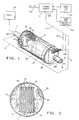
- a sanitizing electrode assembly apparatus for delivering brominated water to a body of water, the assembly comprising a canister 5 having an inlet 7 for an aqueous sodium bromide electrolyte, preferably from a swimming pool, and an outlet 8 for brominated water.
- a canister 5 having an inlet 7 for an aqueous sodium bromide electrolyte, preferably from a swimming pool, and an outlet 8 for brominated water.
- an anode 9 and a cathode 9a positioned in the canister and a plurality of bipolar electrode graphite plates 10 separated from the anode and cathode and from each other with the electrolyte.
- the anode and the cathode electrodes are connected to a direct current source 12 , by wires 14, 14a and 14b and wires 16 and 17 are connected to grounds 18a and 18b .
- a direct current source 12 by wires 14, 14a and 14b and wires 16 and 17 are connected to grounds 18a and 18b .
- There is provided means for passing the electrolyte through the canister including a typical circulating pump 20, there preferably being a typical filter (not shown) and an electrically operated on-off flow switch mounted in the feedline between the circulating pump 20 and the inlet of the canister 5.
- the filter generally helps provide clean electrolyte for flowing through the canister.
- a typical a.c. power source is used, the a.c. current being rectified to provide a direct current power supply for the electrode.
- the assembly has means for applying direct current to the anode and bipolar electrode, and means for reversing the polarity of the bipolar electrodes at given intervals to help clean unwanted deposits (principally calcium carbonate) from the graphite plates 10 . It is advantageous in this regard to change the polarity at intervals of from about 3 to about 10 minutes.
- the assembly has power control timing means 25 for turning the direct current on and off, including timing adjust means for determining the percentage of time the unit is off during each cycle.
- Each cycle is between from about 1 to about 60 seconds, and is preferably about 10 seconds.
- the on/off timing allows the user to control the rate of bromine generation as well as aiding in the cleansing of the electrode plates.
- the apparatus includes polarity changing on/off switching means 25a for turning the power off about generally 1 to 10 seconds, and preferably 3 to 8 seconds just prior to reversing the polarity of the anode and cathode and the polarity of the faces of the bipolar electrodes 10. This short shut-off time is highly advantageous for cleaning the plates 10 and providing an efficient electrolyte cell.
- the apparatus also has means for controlling the flow of electrolyte through the canister including mounting plate means 30 for the bipolar electrodes and apertures 32 in the mounting plate means to regulate fluid velocity at 0.9 - 1.8 ms -1 (3 to 6 feet per second) and provide an efficient flow between the bipolar electrode 10.
- the apparatus shown has the mounting plate means 30 that comprises three (two would suffice) mounting plates, each plate having a plurality of apertures 32 to control the flow of electrolyte.
- the graphite plates 10 are held in place by the mounts 30, the walls of the canister preferably being transparent to show the interior of the canister.
- the mounts have small holes 35 for wires 14a, 14b carrying d.c. power to the feeder anode and cathode.
- a preferred method of the invention is illustrated in the flowsheet of Fig. 3, the method including passing the sodium bromide electrolyte (such as from a swimming pool) through the electrolytes cell canister having an anode 9 , a cathode 9a, and bipolar electrode graphite plates 10 .
- One of the improvements in the present method is in controlling the flow of electrolyte around the graphite plates.
- the outstanding method steps are:
- the d.c. power delivered to the electrode is with constant amperage and efficiently uses both halves of the sine wave curve.
- a bromine rate switch means has a low power setting for an economical normal bromine rate production of say, 1 to 3 ppm bromine water, in which only one-half of the sine curve (power train wave) is used.
- the rate switch when on a high setting, delivers, say 5 to 6 ppm bromine water at about double the power of the low setting.
- the invention contemplates bromide content of about 1 to 9 ppm.
- the canister size is matched to the pump and the flow rate adjusted and controlled with apertures in the mount plates.
- the canister with the graphite electrode plates is easy to use and consumes a small amount of power.
- the graphite plates for use in commercial applications are generally used with about a 4.76 mm (3/16" )gap, while plates used in residential applications are used with about 3.2 mm (1/8") gap.
- the graphite plate assembly for one unit generally has 4 to 8 bipolar graphite plates electrodes and generally unipolar electrodes along the lines shown in Figures 1 and 2 of the previously discussed McCallum U.S. Patent No. 4,085,028.
- the bipolar electrode assembly usually has four to eight graphite electrode plates held within the canister with a gap 34 of 3.2 mm (1/8") or more as seen especially in Figure 2.
- the a.c. current is usually 110 volts, 60 hz and 15 amps although 200 volt current can be used.
- the d.c. output current is about 1 to 30 amps and preferably 2 to 8 amps, depending upon the concentration of the sodium bromide solution.
- the d.c. output voltage is about 20 to 90 volts and preferably about 30 volts. Occasionally the build-up of calcium carbonate can be removed easily with HCl, the plates cleaning up in only 3 to 4 minutes, compared to 30 minutes or more prior to the present invention.
Landscapes
- Chemical & Material Sciences (AREA)
- Engineering & Computer Science (AREA)
- Chemical Kinetics & Catalysis (AREA)
- Electrochemistry (AREA)
- Organic Chemistry (AREA)
- Materials Engineering (AREA)
- Metallurgy (AREA)
- General Chemical & Material Sciences (AREA)
- Life Sciences & Earth Sciences (AREA)
- Hydrology & Water Resources (AREA)
- Environmental & Geological Engineering (AREA)
- Water Supply & Treatment (AREA)
- Inorganic Chemistry (AREA)
- Electrolytic Production Of Non-Metals, Compounds, Apparatuses Therefor (AREA)
- Water Treatment By Electricity Or Magnetism (AREA)
- Organic Low-Molecular-Weight Compounds And Preparation Thereof (AREA)
- Electrodes For Compound Or Non-Metal Manufacture (AREA)
Abstract
Description
Claims (13)
- A method for electrolytically producing bromine from an aqueous electrolyte bromide solution to provide brominated water for sanitizing a body of water, the method comprising pumping the bromide solution through an electrolytic cell, said electrolytic cell including a canister (5) having a compartment that houses two electrodes (9, 9a) functioning as an anode and a cathode, and a plurality of bipolar planar electrode plates (10) in spaced apart relationship between the anode and the cathode and parallel to a flow of the bromide solution moving from an input end (7) of the canister across the electrode plates and out an output end (8) of the canister, supplying a direct current from a power supply (12) to the electrolytic cell in an adjustable operating cycle controlled by a DC power timer (25), the direct current from the power supply establishing a polarity at the anode and cathode and passing through the bipolar electrode plates and the aqueous solution in the electrolytic cell to produce brominated water, directing the brominated water from the canister to the body of water for sanitizing the body of water, reversing the polarity of the electrodes functioning as the anode and the cathode in an adjustable polarity cycle controlled by a polarity timer (25a), the polarity of the anode and the cathode being switched to result in the bipolar electrode plates alternatively functioning as an anode on one face and as a cathode on the other face whereby brominated water with the desired bromine concentration is supplied to the body of water,
characterised in that the operating cycle is about 1-60 seconds in length and is defined by connecting the power supply to the anode and cathode for part of the cycle and by disconnecting the power supply from the anode and cathode for the balance of the operating cycle, the polarity cycle being controlled by a polarity timer (25a) to disconnect the direct current power supply from the anode and the cathode for approximately 3 to 10 seconds prior to the reversing of the polarity of the electrodes monitoring the bromine content of the brominated water and the build-up of a deposit on the electrodes, and adjusting the DC power timer (25) to control the operating cycle and adjusting the polarity timer to control the polarity cycle and cause polarity switching an intervals between 3 and 10 minutes. - A method as defined in Claim 1 in which the operating cycle is about 1 to 10 seconds.
- A method as defined in Claim 1 in which the direct current is supplied at a constant amperage.
- A method as defined in Claim 1 in which there is a further step of controlling the flow of the bromide solution by apertures (32) to provide an efficient flow velocity of about .9-1.8 mps (3 to 6 ft./second) through the electrode plates.
- A method as defined in Claim 1 in which the direct current is supplied at a constant amperage, the amperage selected to provide the brominated water with a bromine content of about 1 to 9 parts per million.
- The method as defined in Claim 1 in which there is a further step of controlling the flow of the bromide solution through a pair of mounting plates in the canister and across the electrodes supported by the mounting plates by directing a portion of the flow through a set of side apertures in the mounting plates.
- A method as defined in Claim 1 in which a sodium bromide electrolyte is used and the operating cycle is approximately 10 seconds, and includes being connected to the power supply for seconds and being disconnected from the power supply for 3 seconds.
- A method as defined in Claim 7 in which the power is turned off approximately 5 seconds prior to the reversing of one polarity of the anode and cathode.
- A method as defined in Claim 1 in which there is a further step of selecting a low power setting for bromine production of 1 to 3 parts per million or a high power setting for bromide production of 5 to 6 parts per million.
- A sanitizing electrode assembly apparatus for delivering brominated water to a body of water, the assembly comprising a canister (5) having an inlet (7) for an aqueous bromide electrolyte and an outlet for brominated water, an anode and a cathode (9,9a) positioned in the canister and a plurality of bipolar electrode plates (10) in spaced apart relationship between the anode and the cathode and parallel to a flow of electrolyte from the inlet, across the electrode plates, and out the outlet, means (20) for passing the electrolyte through the canister, power supply means (12) for selectively supplying a direct current from a direct current source to the anode and cathode, and for establishing a polarity for the anode, the cathode, and the bipolar plates, control means (25a) for reversing the polarity of the anode and the cathode which reverses the polarity for the bipolar plates, said control means including an adjustable timer for establishing polarity cycle time,
characterised in that first control means (25) are provided for determining an operating cycle for said power supply means, said first control means being provided with adjustable timers for establishing the operating cycle, including an adjustable time period during which the power supply means is connected to the anode and the cathode and an adjustable time period during which the power supply means is disconnected, and polarity switching means for selectively disconnecting the power supply means from the anode and the cathode prior to reversing the polarity of the anode and the cathode. - An apparatus as defined in Claim 10 wherein the polarity switching means includes a timer switch for disconnecting the power supply means from the anode and the cathode for about 1 to 10 seconds prior to reversing the polarity of the anode and cathode.
- An apparatus as defined in Claim 10 including means for controlling the flow of electrolyte through the canister, said means for controlling the flow including mounting plate means being mounted in said canister for supporting the bipolar electrodes, the mounting plate means being provided with a plurality of side apertures for directing a portion of the flow of the electrolyte around the bipolar electrode plates to provide an efficient flow for the electrolyte passing through the electrodes for bromination.
- An apparatus as defined in Claim 12 wherein the mounting plate means comprises at least- two plates, each plate having a plurality of apertures to provide a bypass for the flow of electrolyte and to control the flow of electrolyte through the electrodes for bromination.
Applications Claiming Priority (3)
| Application Number | Priority Date | Filing Date | Title |
|---|---|---|---|
| US07/878,682 US5254226A (en) | 1992-05-05 | 1992-05-05 | Electrolytic cell assembly and process for production of bromine |
| US878682 | 1992-05-05 | ||
| PCT/US1993/004206 WO1993022477A1 (en) | 1992-05-05 | 1993-05-04 | Electrolytic cell assembly and process for production of bromine |
Publications (3)
| Publication Number | Publication Date |
|---|---|
| EP0635072A1 EP0635072A1 (en) | 1995-01-25 |
| EP0635072A4 EP0635072A4 (en) | 1995-02-22 |
| EP0635072B1 true EP0635072B1 (en) | 1999-04-07 |
Family
ID=25372573
Family Applications (1)
| Application Number | Title | Priority Date | Filing Date |
|---|---|---|---|
| EP93911044A Expired - Lifetime EP0635072B1 (en) | 1992-05-05 | 1993-05-04 | Electrolytic cell assembly and process for production of bromine |
Country Status (10)
| Country | Link |
|---|---|
| US (2) | US5254226A (en) |
| EP (1) | EP0635072B1 (en) |
| JP (1) | JPH07501487A (en) |
| AT (1) | ATE178663T1 (en) |
| AU (1) | AU658317B2 (en) |
| CA (1) | CA2112677C (en) |
| DE (1) | DE69324355T2 (en) |
| ES (1) | ES2131580T3 (en) |
| IL (1) | IL105608A (en) |
| WO (1) | WO1993022477A1 (en) |
Cited By (1)
| Publication number | Priority date | Publication date | Assignee | Title |
|---|---|---|---|---|
| EP4355695A4 (en) * | 2021-06-15 | 2025-04-23 | TTD Global Pty Ltd | In-line electrochemical reactor |
Families Citing this family (47)
| Publication number | Priority date | Publication date | Assignee | Title |
|---|---|---|---|---|
| US5359769A (en) * | 1989-03-06 | 1994-11-01 | Silveri Michael A | Installation method for pool purifier |
| US5580438A (en) * | 1989-08-18 | 1996-12-03 | Silveri; Michael A. | Pool purifier attaching apparatus and method |
| US5401373A (en) * | 1989-08-18 | 1995-03-28 | Silveri; Michael A. | Electrolytic pool purifier |
| USRE37055E1 (en) | 1989-08-18 | 2001-02-20 | Michael A. Silveri | Pool purifier attaching apparatus and method |
| AU682055B2 (en) * | 1993-10-27 | 1997-09-18 | Alcides dos Santos Lisboa | Electrolytic cell for the generation of hypo halogenites for water treatment |
| AUPM498394A0 (en) * | 1994-04-12 | 1994-05-05 | Berrett Pty Ltd | Electrolytic water treatment |
| AU685260B2 (en) * | 1994-04-12 | 1998-01-15 | Berrett Pty Ltd | Electrolytic water treatment |
| JP3412267B2 (en) * | 1994-06-30 | 2003-06-03 | 東陶機器株式会社 | Water electrolysis treatment method and apparatus |
| US5685963A (en) * | 1994-10-31 | 1997-11-11 | Saes Pure Gas, Inc. | In situ getter pump system and method |
| ZA962117B (en) * | 1995-03-27 | 1996-09-26 | Electrocatalytic Inc | Process and apparatus for generating bromine |
| US6007693A (en) | 1995-03-30 | 1999-12-28 | Bioquest | Spa halogen generator and method of operating |
| US5759384A (en) | 1995-03-30 | 1998-06-02 | Bioquest | Spa halogen generator and method of operating |
| US5676805A (en) | 1995-03-30 | 1997-10-14 | Bioquest | SPA purification system |
| US5752282A (en) | 1995-03-30 | 1998-05-19 | Bioquest | Spa fitting |
| US5545310A (en) | 1995-03-30 | 1996-08-13 | Silveri; Michael A. | Method of inhibiting scale formation in spa halogen generator |
| DE19703900A1 (en) * | 1997-02-03 | 1998-08-06 | Eastman Kodak Co | Method for monitoring the electrolyte circulation in an electrolytic cell |
| US5989396A (en) * | 1997-04-02 | 1999-11-23 | Eltech Systems Corporation | Electrode and electrolytic cell containing same |
| US6238555B1 (en) | 1997-11-07 | 2001-05-29 | Bioquest | Amperometric halogen control system |
| US6086746A (en) * | 1998-03-27 | 2000-07-11 | Albemarle Corporation | Efficient inhibition of bacterial and algicidal activity in aqueous media |
| DE19837641C2 (en) * | 1998-08-19 | 2000-11-02 | Siemens Ag | Method for routing connections over a packet-oriented communication network |
| DE19851164C2 (en) * | 1998-11-06 | 2003-04-10 | Draeger Safety Ag & Co Kgaa | Method and device for operating an electrochemical measuring cell |
| AU745501C (en) * | 1998-12-07 | 2003-01-16 | Integrated Pool Products (Proprietary) Limited | Water chlorinator |
| FR2790268B1 (en) * | 1999-02-25 | 2001-05-11 | Suisse Electronique Microtech | ELECTROLYSIS CELL WITH BIPOLAR ELECTRODE COMPRISING DIAMOND |
| US20030221971A1 (en) * | 2002-06-04 | 2003-12-04 | Keister Timothy Edward | Method for electrolytic production of hypobromite for use as a biocide |
| US8585999B2 (en) * | 2002-06-04 | 2013-11-19 | Prochemtech International, Inc. | Method of making flow-through-resin-impregnated monolithic graphite electrode and containerless electrolytic cell comprising same |
| US7927470B2 (en) * | 2002-06-04 | 2011-04-19 | Prochemtech International, Inc. | Flow-through-resin-impregnated monolithic graphite electrode and containerless electrolytic cell comprising same |
| JP3957619B2 (en) * | 2002-11-22 | 2007-08-15 | シャープ株式会社 | Ion elution unit and equipment equipped with the same |
| US6811679B2 (en) * | 2003-03-28 | 2004-11-02 | Council Of Scientific & Industrial Research | Process for electrochemical oxidation of bromide to bromine |
| WO2005042398A2 (en) * | 2003-10-29 | 2005-05-12 | Rheodyne, Llc | Dosing engine and cartridge apparatus for liquid dispensing and method |
| DE102004026447B4 (en) * | 2004-05-29 | 2009-09-10 | Verein für Kernverfahrenstechnik und Analytik Rossendorf e.V. | Process and apparatus for separating sulfate ions from waters and for introducing buffer capacity into waters |
| US7351331B2 (en) * | 2004-09-08 | 2008-04-01 | Pioneer H20 Technologies, Inc. | Recreational spa including a bromine generator |
| US8961753B2 (en) * | 2005-12-05 | 2015-02-24 | Balboa Water Group, Inc. | Electrolytic cell assembly |
| US20090229992A1 (en) * | 2006-11-28 | 2009-09-17 | Miox Corporation | Reverse Polarity Cleaning and Electronic Flow Control Systems for Low Intervention Electrolytic Chemical Generators |
| EP2518021A4 (en) * | 2009-12-25 | 2013-10-09 | Morinaga Milk Industry Co Ltd | DEVICE FOR PRODUCING ELECTROLYSED WATER |
| DK3257819T3 (en) | 2010-08-06 | 2020-01-13 | De Nora Holdings Us Inc | Electrolytic on-site generator |
| GB201017346D0 (en) * | 2010-10-14 | 2010-11-24 | Advanced Oxidation Ltd | A bipolar cell for a reactor for treatment of waste water and effluent |
| US8992691B2 (en) | 2011-04-05 | 2015-03-31 | International Business Machines Corporation | Partial solution replacement in recyclable persulfuric acid cleaning systems |
| EP4177224A1 (en) | 2011-07-29 | 2023-05-10 | Hayward Industries, Inc. | Chlorinator with replaceable cell cartridge |
| CN102897874A (en) * | 2011-07-29 | 2013-01-30 | 通用电气公司 | Method for preparing bactericide |
| AU2012290215A1 (en) | 2011-07-29 | 2014-03-06 | Hayward Industries, Inc. | Systems and methods for controlling chlorinators |
| ES2934683T3 (en) * | 2012-10-05 | 2023-02-24 | De Nora Holdings Us Inc | Transformerless on-site generation |
| FR3018527B1 (en) * | 2014-03-13 | 2016-03-04 | Conseil Realisations Electroniques Corelec | ELECTROLYTIC CELL COMPRISING AN OVERMOLD PROTECTIVE BODY AND METHOD OF MANUFACTURING SUCH AN ELECTROLYTIC CELL |
| WO2016094591A1 (en) | 2014-12-09 | 2016-06-16 | Miox Corporation | Methods for the direct electrolytic production of stable, high concentration aqueous halosulfamate or halosulfonamide solutions |
| EP3309129B1 (en) * | 2015-06-11 | 2020-07-15 | Kurita Water Industries Ltd. | Electrolysis device, and water treatment method |
| US10228359B2 (en) | 2017-03-16 | 2019-03-12 | Gecko Alliance Group Inc. | Method, device and apparatus for monitoring halogen levels in a body of water |
| EP3602024A4 (en) | 2017-03-21 | 2020-11-18 | Hayward Industries, Inc. | SYSTEMS AND PROCEDURES FOR HYGIENIZATION OF SWIMMING POOL AND SPA WATER |
| US12404592B2 (en) | 2018-05-02 | 2025-09-02 | Ohio State Innovation Foundation | Heteroatom-doped carbon catalyst for electrocatalytic halogen production |
Family Cites Families (30)
| Publication number | Priority date | Publication date | Assignee | Title |
|---|---|---|---|---|
| US943188A (en) * | 1908-03-02 | 1909-12-14 | Mcdowell Mfg Co | Method of purifying water electrolytically. |
| FR1227164A (en) * | 1959-06-17 | 1960-08-19 | Process and installation for the purification and sterilization of swimming pool water | |
| US3305472A (en) * | 1963-03-13 | 1967-02-21 | Dow Chemical Co | Purifying water with bromine |
| US3351542A (en) * | 1966-11-14 | 1967-11-07 | Dow Chemical Co | Electrolytic chlorination and ph control of swimming pool water |
| US3458414A (en) * | 1967-11-24 | 1969-07-29 | William W T Crane | Swimming pool water conditioner |
| US3600286A (en) * | 1968-02-26 | 1971-08-17 | Selectro Chem Co | Electrolytic treatment of aqueous solutions |
| US3701728A (en) * | 1970-05-22 | 1972-10-31 | Terminal Testing Lab Inc | Water purification system |
| US3669857A (en) * | 1970-07-30 | 1972-06-13 | Ionics | ELECTROLYTIC CHLORINATION AND pH CONTROL OF WATER |
| FR2138310B1 (en) * | 1971-05-24 | 1973-05-25 | Herbert Jean Jacques | |
| GB1420197A (en) * | 1971-12-21 | 1976-01-07 | Morgan Berkeley Co Ltd | Electrolytic chlorinator |
| US4085028A (en) * | 1974-11-21 | 1978-04-18 | Electro-Chlor Corporation | Electrolytic chlorination device |
| US4142959A (en) * | 1974-11-21 | 1979-03-06 | Electro-Chlor Corporation | Electrode assembly |
| US4033871A (en) * | 1975-11-13 | 1977-07-05 | Paddock Of California, Inc. | Integrated monitor and control system for continuously monitoring and controlling pH and free halogen in swimming pool water |
| US4100052A (en) * | 1976-11-11 | 1978-07-11 | Diamond Shamrock Corporation | Electrolytic generation of halogen biocides |
| AU3803078A (en) * | 1978-07-13 | 1978-09-04 | ||
| US4263114A (en) * | 1978-08-14 | 1981-04-21 | Shindell Herman A | Methods for the treatment of water |
| US4255246A (en) * | 1979-01-29 | 1981-03-10 | Davis David W | Electrolytic cell for chlorine production |
| DE2911288C2 (en) * | 1979-03-22 | 1984-08-30 | Bernd 8000 München Eder | Method for disinfecting water, in particular swimming pool water |
| NL7904150A (en) * | 1979-05-25 | 1980-11-27 | Magneto Chemie Bv | METHOD FOR PERFORMING AN ELECTROLYSIS PROCESS, AND AN ELECTROLYSIS DEVICE SUITABLE FOR IT. |
| US4256552A (en) * | 1979-11-08 | 1981-03-17 | Sweeney Charles T | Chlorine generator |
| US4332659A (en) * | 1979-12-17 | 1982-06-01 | Hooker Chemicals & Plastics Corp. | Electrolytic apparatus for the manufacture of alkali metal halate |
| US4384943A (en) * | 1980-09-11 | 1983-05-24 | The University Of Virginia Alumni Patents Foundation | Fluid treatment |
| GB2092774B (en) * | 1981-02-06 | 1984-09-26 | Ultimar Products Ltd | Water purification control circuit |
| US4568440A (en) * | 1983-08-30 | 1986-02-04 | Eltech Systems Corporation | Bipolar electrolyzer having fixedly spaced apart electrodes |
| SE448867B (en) * | 1985-05-29 | 1987-03-23 | Electrocell Ab | APPARATUS FOR CHLORING A LIQUID LIKE THE WATER |
| US4714534A (en) * | 1986-06-20 | 1987-12-22 | Olin Corporation | Electrolytic halogenator device |
| US4781805A (en) * | 1988-02-16 | 1988-11-01 | Vincent Dahlgren | Method for controlling pollution and reducing calcium concentration in aqueous bodies |
| US4917782A (en) * | 1988-03-02 | 1990-04-17 | Advanced Water Systems, Inc. | Electrolytic liquid purification process and apparatus |
| AU619050B2 (en) * | 1988-10-11 | 1992-01-16 | Sal-Chlor Pty. Ltd. | Improvements in pool chlorinators |
| SU1673643A1 (en) * | 1989-03-31 | 1991-08-30 | Институт геохимии и аналитической химии им.В.И.Вернадского | Method of recovering bromine from oceanic water |
-
1992
- 1992-05-05 US US07/878,682 patent/US5254226A/en not_active Ceased
-
1993
- 1993-05-04 CA CA002112677A patent/CA2112677C/en not_active Expired - Lifetime
- 1993-05-04 AT AT93911044T patent/ATE178663T1/en not_active IP Right Cessation
- 1993-05-04 EP EP93911044A patent/EP0635072B1/en not_active Expired - Lifetime
- 1993-05-04 WO PCT/US1993/004206 patent/WO1993022477A1/en not_active Ceased
- 1993-05-04 DE DE69324355T patent/DE69324355T2/en not_active Expired - Fee Related
- 1993-05-04 ES ES93911044T patent/ES2131580T3/en not_active Expired - Lifetime
- 1993-05-04 AU AU42326/93A patent/AU658317B2/en not_active Ceased
- 1993-05-04 JP JP5519598A patent/JPH07501487A/en active Pending
- 1993-05-05 IL IL10560893A patent/IL105608A/en not_active IP Right Cessation
-
1995
- 1995-10-18 US US08/544,530 patent/USRE36402E/en not_active Expired - Lifetime
Cited By (1)
| Publication number | Priority date | Publication date | Assignee | Title |
|---|---|---|---|---|
| EP4355695A4 (en) * | 2021-06-15 | 2025-04-23 | TTD Global Pty Ltd | In-line electrochemical reactor |
Also Published As
| Publication number | Publication date |
|---|---|
| EP0635072A4 (en) | 1995-02-22 |
| EP0635072A1 (en) | 1995-01-25 |
| CA2112677A1 (en) | 1993-11-11 |
| CA2112677C (en) | 2005-07-05 |
| WO1993022477A1 (en) | 1993-11-11 |
| IL105608A (en) | 1996-08-04 |
| DE69324355D1 (en) | 1999-05-12 |
| IL105608A0 (en) | 1993-09-22 |
| US5254226A (en) | 1993-10-19 |
| USRE36402E (en) | 1999-11-23 |
| JPH07501487A (en) | 1995-02-16 |
| AU658317B2 (en) | 1995-04-06 |
| DE69324355T2 (en) | 1999-11-25 |
| ATE178663T1 (en) | 1999-04-15 |
| AU4232693A (en) | 1993-11-29 |
| ES2131580T3 (en) | 1999-08-01 |
Similar Documents
| Publication | Publication Date | Title |
|---|---|---|
| US5254226A (en) | Electrolytic cell assembly and process for production of bromine | |
| US4129493A (en) | Swimming pool chlorinator system | |
| AU569309B2 (en) | Water sterilisation apparatus | |
| US4048032A (en) | Electrolytic purification of aqueous liquids in the presence of silver ions | |
| US4306952A (en) | Electrolytic process and apparatus | |
| US4719018A (en) | Automatic water purifier | |
| AU6317199A (en) | Water chlorinator | |
| US8486252B2 (en) | Copper chloride/copper bromide disinfector for swimming pools and control method thereof | |
| JPS6059995B2 (en) | Impure salt water electrolysis method and device | |
| US6827847B1 (en) | System and assembly for sanitizing swimming pool water | |
| US7695606B2 (en) | Electrolytic device and method for disinfecting water in a water supply system by means of the generation of active chlorine | |
| CA3092401A1 (en) | Electrolysis method and device for spas and pools | |
| JP3843365B2 (en) | Water purification method and mechanism | |
| EP1226094B1 (en) | Device for electrolysis | |
| RU2139956C1 (en) | Plant for production of hypochlorites solutions by electrolysis | |
| JPH0910769A (en) | Production of electrolytic ion water | |
| JPH09206755A (en) | Formation of alkaline ionized and hypochlorous acid sterilizing water and device therefor | |
| JP2003034889A (en) | Electrolysis method for strong electrolyzed water generator | |
| JP2003126858A (en) | Method for producing electrolyzed water | |
| JP3359661B2 (en) | Method for cleaning / sterilizing a continuous electrolytic water regulator and an electrolytic water regulator provided with a mechanism for performing the method | |
| JP2000126775A (en) | Method and apparatus for electrolytic sterilization | |
| JP3297828B2 (en) | Electrolyzed water generator and method for controlling chloride ion concentration in the electrolyzed water generator | |
| JPH09108673A (en) | Method of electrolyzing salt water | |
| JPH1071392A (en) | Electrolytic fresh water generator | |
| JP2004216380A (en) | Method for producing electrolytic water |
Legal Events
| Date | Code | Title | Description |
|---|---|---|---|
| PUAI | Public reference made under article 153(3) epc to a published international application that has entered the european phase |
Free format text: ORIGINAL CODE: 0009012 |
|
| 17P | Request for examination filed |
Effective date: 19940316 |
|
| AK | Designated contracting states |
Kind code of ref document: A1 Designated state(s): AT BE CH DE DK ES FR GB GR IE IT LI LU MC NL PT SE |
|
| A4 | Supplementary search report drawn up and despatched | ||
| AK | Designated contracting states |
Kind code of ref document: A4 Designated state(s): AT BE CH DE DK ES FR GB GR IE IT LI LU MC NL PT SE |
|
| 17Q | First examination report despatched |
Effective date: 19951024 |
|
| GRAG | Despatch of communication of intention to grant |
Free format text: ORIGINAL CODE: EPIDOS AGRA |
|
| GRAG | Despatch of communication of intention to grant |
Free format text: ORIGINAL CODE: EPIDOS AGRA |
|
| GRAH | Despatch of communication of intention to grant a patent |
Free format text: ORIGINAL CODE: EPIDOS IGRA |
|
| GRAH | Despatch of communication of intention to grant a patent |
Free format text: ORIGINAL CODE: EPIDOS IGRA |
|
| GRAA | (expected) grant |
Free format text: ORIGINAL CODE: 0009210 |
|
| AK | Designated contracting states |
Kind code of ref document: B1 Designated state(s): AT BE CH DE DK ES FR GB GR IE IT LI LU MC NL PT SE |
|
| PG25 | Lapsed in a contracting state [announced via postgrant information from national office to epo] |
Ref country code: SE Free format text: THE PATENT HAS BEEN ANNULLED BY A DECISION OF A NATIONAL AUTHORITY Effective date: 19990407 Ref country code: NL Free format text: LAPSE BECAUSE OF FAILURE TO SUBMIT A TRANSLATION OF THE DESCRIPTION OR TO PAY THE FEE WITHIN THE PRESCRIBED TIME-LIMIT Effective date: 19990407 Ref country code: LI Free format text: LAPSE BECAUSE OF FAILURE TO SUBMIT A TRANSLATION OF THE DESCRIPTION OR TO PAY THE FEE WITHIN THE PRESCRIBED TIME-LIMIT Effective date: 19990407 Ref country code: GR Free format text: LAPSE BECAUSE OF NON-PAYMENT OF DUE FEES Effective date: 19990407 Ref country code: CH Free format text: LAPSE BECAUSE OF FAILURE TO SUBMIT A TRANSLATION OF THE DESCRIPTION OR TO PAY THE FEE WITHIN THE PRESCRIBED TIME-LIMIT Effective date: 19990407 Ref country code: BE Free format text: LAPSE BECAUSE OF FAILURE TO SUBMIT A TRANSLATION OF THE DESCRIPTION OR TO PAY THE FEE WITHIN THE PRESCRIBED TIME-LIMIT Effective date: 19990407 Ref country code: AT Free format text: LAPSE BECAUSE OF FAILURE TO SUBMIT A TRANSLATION OF THE DESCRIPTION OR TO PAY THE FEE WITHIN THE PRESCRIBED TIME-LIMIT Effective date: 19990407 |
|
| REF | Corresponds to: |
Ref document number: 178663 Country of ref document: AT Date of ref document: 19990415 Kind code of ref document: T |
|
| REG | Reference to a national code |
Ref country code: CH Ref legal event code: EP |
|
| PG25 | Lapsed in a contracting state [announced via postgrant information from national office to epo] |
Ref country code: LU Free format text: LAPSE BECAUSE OF NON-PAYMENT OF DUE FEES Effective date: 19990504 |
|
| PG25 | Lapsed in a contracting state [announced via postgrant information from national office to epo] |
Ref country code: ES Free format text: LAPSE BECAUSE OF NON-PAYMENT OF DUE FEES Effective date: 19990505 |
|
| REG | Reference to a national code |
Ref country code: IE Ref legal event code: FG4D |
|
| REF | Corresponds to: |
Ref document number: 69324355 Country of ref document: DE Date of ref document: 19990512 |
|
| PG25 | Lapsed in a contracting state [announced via postgrant information from national office to epo] |
Ref country code: IE Free format text: LAPSE BECAUSE OF NON-PAYMENT OF DUE FEES Effective date: 19990607 |
|
| PG25 | Lapsed in a contracting state [announced via postgrant information from national office to epo] |
Ref country code: PT Free format text: LAPSE BECAUSE OF FAILURE TO SUBMIT A TRANSLATION OF THE DESCRIPTION OR TO PAY THE FEE WITHIN THE PRESCRIBED TIME-LIMIT Effective date: 19990707 Ref country code: DK Free format text: LAPSE BECAUSE OF FAILURE TO SUBMIT A TRANSLATION OF THE DESCRIPTION OR TO PAY THE FEE WITHIN THE PRESCRIBED TIME-LIMIT Effective date: 19990707 |
|
| REG | Reference to a national code |
Ref country code: ES Ref legal event code: FG2A Ref document number: 2131580 Country of ref document: ES Kind code of ref document: T3 |
|
| ET | Fr: translation filed | ||
| NLV1 | Nl: lapsed or annulled due to failure to fulfill the requirements of art. 29p and 29m of the patents act | ||
| REG | Reference to a national code |
Ref country code: CH Ref legal event code: PL |
|
| PG25 | Lapsed in a contracting state [announced via postgrant information from national office to epo] |
Ref country code: MC Free format text: LAPSE BECAUSE OF NON-PAYMENT OF DUE FEES Effective date: 19991130 |
|
| PLBE | No opposition filed within time limit |
Free format text: ORIGINAL CODE: 0009261 |
|
| STAA | Information on the status of an ep patent application or granted ep patent |
Free format text: STATUS: NO OPPOSITION FILED WITHIN TIME LIMIT |
|
| GBPC | Gb: european patent ceased through non-payment of renewal fee |
Effective date: 19990707 |
|
| 26N | No opposition filed | ||
| REG | Reference to a national code |
Ref country code: IE Ref legal event code: MM4A |
|
| REG | Reference to a national code |
Ref country code: FR Ref legal event code: ST |
|
| REG | Reference to a national code |
Ref country code: FR Ref legal event code: RN |
|
| REG | Reference to a national code |
Ref country code: FR Ref legal event code: FC |
|
| REG | Reference to a national code |
Ref country code: GB Ref legal event code: 728V |
|
| REG | Reference to a national code |
Ref country code: GB Ref legal event code: 728Y |
|
| REG | Reference to a national code |
Ref country code: GB Ref legal event code: IF02 |
|
| REG | Reference to a national code |
Ref country code: ES Ref legal event code: FD2A Effective date: 20000610 |
|
| PG25 | Lapsed in a contracting state [announced via postgrant information from national office to epo] |
Ref country code: IT Free format text: LAPSE BECAUSE OF NON-PAYMENT OF DUE FEES;WARNING: LAPSES OF ITALIAN PATENTS WITH EFFECTIVE DATE BEFORE 2007 MAY HAVE OCCURRED AT ANY TIME BEFORE 2007. THE CORRECT EFFECTIVE DATE MAY BE DIFFERENT FROM THE ONE RECORDED. Effective date: 20050504 |
|
| PGFP | Annual fee paid to national office [announced via postgrant information from national office to epo] |
Ref country code: DE Payment date: 20090525 Year of fee payment: 17 |
|
| PGFP | Annual fee paid to national office [announced via postgrant information from national office to epo] |
Ref country code: FR Payment date: 20100622 Year of fee payment: 18 |
|
| PGFP | Annual fee paid to national office [announced via postgrant information from national office to epo] |
Ref country code: GB Payment date: 20100528 Year of fee payment: 18 |
|
| PG25 | Lapsed in a contracting state [announced via postgrant information from national office to epo] |
Ref country code: DE Free format text: LAPSE BECAUSE OF NON-PAYMENT OF DUE FEES Effective date: 20101201 |
|
| GBPC | Gb: european patent ceased through non-payment of renewal fee |
Effective date: 20110504 |
|
| REG | Reference to a national code |
Ref country code: FR Ref legal event code: ST Effective date: 20120131 |
|
| PG25 | Lapsed in a contracting state [announced via postgrant information from national office to epo] |
Ref country code: FR Free format text: LAPSE BECAUSE OF NON-PAYMENT OF DUE FEES Effective date: 20110531 |
|
| PG25 | Lapsed in a contracting state [announced via postgrant information from national office to epo] |
Ref country code: GB Free format text: LAPSE BECAUSE OF NON-PAYMENT OF DUE FEES Effective date: 20110504 |