EP0634856A2 - Nonlinear coding for ISI channels - Google Patents
Nonlinear coding for ISI channels Download PDFInfo
- Publication number
- EP0634856A2 EP0634856A2 EP94304979A EP94304979A EP0634856A2 EP 0634856 A2 EP0634856 A2 EP 0634856A2 EP 94304979 A EP94304979 A EP 94304979A EP 94304979 A EP94304979 A EP 94304979A EP 0634856 A2 EP0634856 A2 EP 0634856A2
- Authority
- EP
- European Patent Office
- Prior art keywords
- signal
- constellation
- trellis
- modulo
- signal point
- Prior art date
- Legal status (The legal status is an assumption and is not a legal conclusion. Google has not performed a legal analysis and makes no representation as to the accuracy of the status listed.)
- Granted
Links
- 238000004891 communication Methods 0.000 claims description 13
- 238000000034 method Methods 0.000 claims description 8
- 230000005540 biological transmission Effects 0.000 abstract description 4
- 238000011084 recovery Methods 0.000 abstract 1
- 230000006870 function Effects 0.000 description 29
- 230000009021 linear effect Effects 0.000 description 22
- 230000002087 whitening effect Effects 0.000 description 10
- 239000003623 enhancer Substances 0.000 description 9
- 238000007792 addition Methods 0.000 description 5
- 230000000694 effects Effects 0.000 description 5
- 238000006467 substitution reaction Methods 0.000 description 4
- 230000007423 decrease Effects 0.000 description 3
- 230000003247 decreasing effect Effects 0.000 description 3
- 238000005192 partition Methods 0.000 description 3
- 230000001934 delay Effects 0.000 description 2
- 238000010586 diagram Methods 0.000 description 2
- 238000005516 engineering process Methods 0.000 description 2
- 230000036039 immunity Effects 0.000 description 2
- 238000005259 measurement Methods 0.000 description 2
- 230000010363 phase shift Effects 0.000 description 2
- 238000012805 post-processing Methods 0.000 description 2
- 238000007781 pre-processing Methods 0.000 description 2
- 238000012545 processing Methods 0.000 description 2
- 230000004044 response Effects 0.000 description 2
- 101100310323 Caenorhabditis elegans sinh-1 gene Proteins 0.000 description 1
- 230000006978 adaptation Effects 0.000 description 1
- 238000013459 approach Methods 0.000 description 1
- 238000004364 calculation method Methods 0.000 description 1
- 238000006243 chemical reaction Methods 0.000 description 1
- 230000000295 complement effect Effects 0.000 description 1
- 230000001419 dependent effect Effects 0.000 description 1
- 239000006185 dispersion Substances 0.000 description 1
- 230000009022 nonlinear effect Effects 0.000 description 1
- 238000007493 shaping process Methods 0.000 description 1
- 230000008054 signal transmission Effects 0.000 description 1
- 238000012549 training Methods 0.000 description 1
- 238000012546 transfer Methods 0.000 description 1
Images


Classifications
-
- H—ELECTRICITY
- H04—ELECTRIC COMMUNICATION TECHNIQUE
- H04L—TRANSMISSION OF DIGITAL INFORMATION, e.g. TELEGRAPHIC COMMUNICATION
- H04L25/00—Baseband systems
- H04L25/38—Synchronous or start-stop systems, e.g. for Baudot code
- H04L25/40—Transmitting circuits; Receiving circuits
- H04L25/49—Transmitting circuits; Receiving circuits using code conversion at the transmitter; using predistortion; using insertion of idle bits for obtaining a desired frequency spectrum; using three or more amplitude levels ; Baseband coding techniques specific to data transmission systems
- H04L25/497—Transmitting circuits; Receiving circuits using code conversion at the transmitter; using predistortion; using insertion of idle bits for obtaining a desired frequency spectrum; using three or more amplitude levels ; Baseband coding techniques specific to data transmission systems by correlative coding, e.g. partial response coding or echo modulation coding transmitters and receivers for partial response systems
- H04L25/4975—Correlative coding using Tomlinson precoding, Harashima precoding, Trellis precoding or GPRS
-
- H—ELECTRICITY
- H04—ELECTRIC COMMUNICATION TECHNIQUE
- H04L—TRANSMISSION OF DIGITAL INFORMATION, e.g. TELEGRAPHIC COMMUNICATION
- H04L25/00—Baseband systems
- H04L25/02—Details ; arrangements for supplying electrical power along data transmission lines
- H04L25/03—Shaping networks in transmitter or receiver, e.g. adaptive shaping networks
- H04L25/03006—Arrangements for removing intersymbol interference
- H04L25/03343—Arrangements at the transmitter end
-
- H—ELECTRICITY
- H04—ELECTRIC COMMUNICATION TECHNIQUE
- H04L—TRANSMISSION OF DIGITAL INFORMATION, e.g. TELEGRAPHIC COMMUNICATION
- H04L25/00—Baseband systems
- H04L25/38—Synchronous or start-stop systems, e.g. for Baudot code
- H04L25/40—Transmitting circuits; Receiving circuits
- H04L25/49—Transmitting circuits; Receiving circuits using code conversion at the transmitter; using predistortion; using insertion of idle bits for obtaining a desired frequency spectrum; using three or more amplitude levels ; Baseband coding techniques specific to data transmission systems
- H04L25/4917—Transmitting circuits; Receiving circuits using code conversion at the transmitter; using predistortion; using insertion of idle bits for obtaining a desired frequency spectrum; using three or more amplitude levels ; Baseband coding techniques specific to data transmission systems using multilevel codes
- H04L25/4927—Transmitting circuits; Receiving circuits using code conversion at the transmitter; using predistortion; using insertion of idle bits for obtaining a desired frequency spectrum; using three or more amplitude levels ; Baseband coding techniques specific to data transmission systems using multilevel codes using levels matched to the quantisation levels of the channel
-
- H—ELECTRICITY
- H04—ELECTRIC COMMUNICATION TECHNIQUE
- H04L—TRANSMISSION OF DIGITAL INFORMATION, e.g. TELEGRAPHIC COMMUNICATION
- H04L25/00—Baseband systems
- H04L25/38—Synchronous or start-stop systems, e.g. for Baudot code
- H04L25/40—Transmitting circuits; Receiving circuits
- H04L25/49—Transmitting circuits; Receiving circuits using code conversion at the transmitter; using predistortion; using insertion of idle bits for obtaining a desired frequency spectrum; using three or more amplitude levels ; Baseband coding techniques specific to data transmission systems
- H04L25/497—Transmitting circuits; Receiving circuits using code conversion at the transmitter; using predistortion; using insertion of idle bits for obtaining a desired frequency spectrum; using three or more amplitude levels ; Baseband coding techniques specific to data transmission systems by correlative coding, e.g. partial response coding or echo modulation coding transmitters and receivers for partial response systems
-
- H—ELECTRICITY
- H04—ELECTRIC COMMUNICATION TECHNIQUE
- H04L—TRANSMISSION OF DIGITAL INFORMATION, e.g. TELEGRAPHIC COMMUNICATION
- H04L27/00—Modulated-carrier systems
- H04L27/32—Carrier systems characterised by combinations of two or more of the types covered by groups H04L27/02, H04L27/10, H04L27/18 or H04L27/26
- H04L27/34—Amplitude- and phase-modulated carrier systems, e.g. quadrature-amplitude modulated carrier systems
- H04L27/3405—Modifications of the signal space to increase the efficiency of transmission, e.g. reduction of the bit error rate, bandwidth, or average power
- H04L27/3416—Modifications of the signal space to increase the efficiency of transmission, e.g. reduction of the bit error rate, bandwidth, or average power in which the information is carried by both the individual signal points and the subset to which the individual points belong, e.g. using coset coding, lattice coding, or related schemes
- H04L27/3427—Modifications of the signal space to increase the efficiency of transmission, e.g. reduction of the bit error rate, bandwidth, or average power in which the information is carried by both the individual signal points and the subset to which the individual points belong, e.g. using coset coding, lattice coding, or related schemes in which the constellation is the n - fold Cartesian product of a single underlying two-dimensional constellation
Definitions
- the invention relates to encoding data for transfer over a communication channel; more specifically, communicating data over a telephone communication channel which is susceptible to inter-symbol interference.
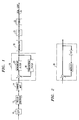
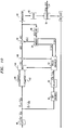
- FIG. 1 illustrates the transmitter disclosed in the aforementioned U.S. Patent.
- Serial-to-parallel converter 10 converts the incoming data to parallel words.
- Trellis encoder 12 encodes the parallel word to provide increased immunity to inter-symbol interference.
- Symbol mapper 14 maps the trellis encoded word to a signal point in a predefined symbol or signal point constellation. The symbol specified by symbol mapper 14 is in the form of a complex number which is received by precoding unit 16.
- Precoding unit 16 is used to compensate for signal distortions that are introduced at a receiver when the receiver passed the symbol through a noise whitening filter. Received symbols are passed through a noise whitening filter to compensate for the communication channel's colored noise and thereby improve proper decoding of the trellis code.
- Precoder 16 includes transversal filter 18 and non-linear filter 20.
- Non-linear filter 20 is in the form of a modulo device that repeatedly subtracts or adds a value of 2L until the output a of the device satisfies -L ⁇ ⁇ ⁇ L.
- Non-linear filter 20 is used to compensate for any instability introduced by filter 18.
- the output of encoder 16 is modulated by modulator 19 using a modulation technique such as QAM (quadrature amplitude modulation).
- QAM quadrature amplitude modulation
- FIG. 2 illustrates the precoder disclosed in the paper.
- Precoder 30 is similar to precoder 16.
- both the FIR filter and the modulo device are in the feedback loop.
- the FIR filter is disclosed as a 3-tap filter and the output of the modulo device is subtracted from the input to the precoder.
- Both of the aforementioned systems precode the data so that there is compensation for the effects of the noise whitening filter in the receiver.
- Both systems have drawbacks.
- the first system is only useful for square symbol constellations and thereby prevents using more efficient constellations.
- the second system uses a relatively large dither signal.
- the large dither signal varies transmitted signal power by a relatively large amount that may exceed the maximum allowable power for the communication channel. As a result, the amount of signal space allotted to the constellation must be decreased to accommodate the variations in transmitted power. Decreasing the constellation's signal space decreases the space between signal points in the constellation and decreases noise immunity.
- the present invention is not limited to square constellations and it decreases the amplitude of the dither signal.
- the dither signal is decreased by using a smaller modulo value to generate the dither signal while maintaining the ability to recover the original trellis code in the receiver.
- the recoverability of the original trellis code is achieved by using a modulo count, which was formed while producing the dither signal, to select a substitute constellation subset for the constellation subset identified by the trellis encoder.
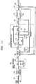
- FIG. 3 illustrates the transmitter section of one embodiment of the present invention.
- Serial data is received by serial-to-parallel converter 40.
- the output of serial-to-parallel converter 40 is an L-bit word.
- Bits 1 to n are sent to differential encoder 42, and the remaining n+1 to L bits are sent to symbol mappers 44a, 44b, 44c, 44d, and 46a, 46b, 46c and 46d.
- Bits n+1 to L are mapped into different signal point or symbol constellation subsets by the mappers. Taken together, the subsets comprise the overall transmit constellation.
- the output of each mapper is a complex number with orthogonal components. The complex number identifies a symbol in a symbol constellation subset.
- the outputs from mappers are received by mux 48.
- Differential encoder 42 differentially encodes some of bits 1 through n. Differentially encoded bits, as well as the unchanged data bits, are passed to trellis encoder 50. Trellis encoder 50 produces trellis bits Y0 through Y n . Bits Y0 through Y n are received by trellis enhancer 52. Trellis enhancer 52 also receives inputs x-count and y-count from modulo device 54. Based on the values Y0-Y n , and the values of x-count and y-count, trellis enhanced controls mux 48 to select one of the mapper outputs. The output of mux 48, signal e(k), is received by summer 58.
- Dither signal d(k) from modulo device 54 is subtracted from signal e(k) in summer 58.
- the output of summer 58, signal x(k), is fed to modulator 60, passband filter 62 and hybrid 64.
- the output of summer 58 is also fed to three-tap finite impulse response (FIR) filter 66.
- the output of filter 66 is received by modulo device 54 to produce outputs x-count, y-count and d(k).
- serial-to-parallel converter 40 produces parallel word (I1-I L ) k .
- Bits I n+1 -I L are passed to the mappers.
- the mappers output a signal point or symbol in a predefined constellation subset based on bits I n+1 - I L .
- FIG. 4 illustrates an 8-way partitioned symbol constellation. Bits I1-I L are encoded as one of the symbols in the constellation.
- the constellation shows that there are eight constellation subsets making up the overall constellation.
- the subsets consist of signal points labeled a, b, c, d, A, B, C and D, where like letters belong to the same subset.
- Data bits I1 through I n and a trellis bit are used to select one of the eight subsets.
- Data bits I n+1 through I L are used to identify a particular symbol or signal point within the subset.
- Differential encoder 40 differentially encodes bits I2 - I3 in accordance with the differential encoding table to produce bits J2 and J3. Bits I1,J2,J3,I4 and I5 are fed to trellis encoder 50.
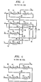
- Trellis encoder 50 can be any finite state machine. These types of state machines are well known in the art and two such state machines are shown in FIGS. 5 and 6. The state machine of FIG. 5 is a 64-state machine and the state machine of FIG. 6 is a 16-state machine. State machines with other numbers of states may be used.
- bits J2,I1,J3 and I4 are used as inputs.
- the outputs of the state machine are bits Y0-Y5, where bits Y1-Y5 equal bits I1,J2,J3,I4 and I5, respectively.
- the devices labeled 80 are adders and the devices labeled 82 are delays. Bits Y0-Y5 are used to identify constellation subsets that are used with remaining bits I n+1 -I L .
- the state machines of FIGS. 5 and 6 are used to output a new Y0 bit every symbol period for two-dimensional trellis encoding, and every other symbol period for 4-dimensional encoding.
- delay elements 82 act as a one-symbol period delay, and if a new output is produced every other symbol period, elements 82 act as two symbol period delays.
- Table 1 of FIG. 7. The Table illustrates which constellation subsets will be used during the two symbol periods. The first letter identifies the constellation subset used during the first symbol period, and the second letter identifies the constellation subset used during the second symbol period.
- bits (I n+1 -I L ) k-1 will be encoded using constellation subset "a” and bits (I n+1 -I L ) k will be encoded using constellation subset "A”.
- bits Y0 - Y3 are used to produce bits Y0 - Y3.
- bits Y1, Y2 and Y3 equal bits I1,J2 and J3, respectively.
- Table 1 is used with Y4 and Y5 set equal to 0, and with lower and upper case forms of the same letter belonging to the same constellation subset.
- n 2 and bits I1 and I2 are fed to the differential encoder.
- the J2 and J3 bits from the differential encoder are used as bits Y2 and Y3.
- two-dimensional coding is used and the differential encoder produces a new output for each symbol period.
- Table 1 is used with Y0, Y1, Y4 and Y5 set equal to 0, and with the second letter in each table entry ignored.
- mappers 44a through 44d, and 46a through 46d identify a symbol in constellation subsets a, b, c, d and A, B, C, D, respectively, based on bits I n+1 -I L .
- the desired mapper output is selected using mux 48 which is controlled by trellis enhancer 52.
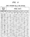
- Table 2 of FIG. 8 illustrates the subset substitutions.
- Trellis enhancer 52 operates mux 48 in accordance with Table 2 so that the proper substitution occurs.
- the output of mux 48 is received by summer 58.
- FIR filter 66 computes output p(k) based on its memory of past transmitted symbols (in the case of a 3-tap filter, the past three symbols).
- FIR filter 66 is a 3-tap filter that is well known in the art. Coefficients for the filter are obtained during training in a manner well known in the art and specified by standards committees such as the ITU (International Telecommunication Union, formerly the CCITT) in ITU Recommendation V.32bis.
- the output of the FIR filter is received by modulo device 54.
- Modulo device 54 performs a modulo operation on each of the orthogonal components of the symbol to produce a separate modulo count, x-cnt and y-cnt, for the X and Y orthogonal components of filter 68's output. If the output of the FIR filter is positive and greater than 2 -m for a particular orthogonal component of p(k), then modulo value 2(2 -m ) is subtracted an integral number of times from that component of p(k) until the result is less than or equal to 2 -m . The number of subtractions is counted by incrementing a respective x or y counter.
- modulo value 2(2 -m ) is added an integral number of times to that component of p(k) until the result is greater than or equal to -2 -m .
- the number of additions is counted by decrementing the respective x or y counter.
- the counters are arithmetic base 4; that is, decrementing two-bit value 00 by 1 produces two-bit value 11, and incrementing two-bit value 11 by 1 produces two-bit value 00.
- signal p(k) The portion of signal p(k) that remains after these subtractions/additions is provided to summer 58 as signal d(k).
- Signal d(k) is called the dither signal.
- trellis enhancer 52 uses x-cnt, y-cnt and bits Y0 through Y n to substitute constellation subsets in accordance with Table 2. (For 4-way partitioned constellations, upper and lower case versions of the same letter are considered identical and only the first four columns of Table 2 are necessary.)
- the resulting output from mux 48 is sent to summer 58 where value d(k) is subtracted to produce signal x(k). This signal is provided to modulator 60, filter 62 and hybrid 64 in a conventional manner.
- the count of additions or subtractions is computed independently for each orthogonal axis of the output from filter 66.
- the counts can be maintained using arithmetic base 4 for 8-way partition constellations and arithmetic base 2 for 4-way partition constellations. These counts are used by the trellis enhancer 52 to perform the substitutions in accordance with Table 2.
- variable modulo device When using large symbol constellations, a larger dither signal is tolerable because the larger dither signal reduces error propagation in the receiver's reconstruction filter. In order to accommodate a variety of constellations it may be desirable to use a variable modulo device.
- a variable modulo device performs similarly to modulo device 54 with the following differences. If the output of the FIR filter is positive and greater than K2 -m for a particular orthogonal component of p(k), then modulo value 2K(2 -m ) is subtracted an integral number of times from that component of p(k) until the result is less than or equal to K2 -m . The number of subtractions is counted by incrementing a respective x or y counter K times the number of subtractions.
- modulo value 2K(2 -m ) is added an integral number of times to that component of p(k) until the result is greater than or equal to -K2 -m .
- the number of additions is counted by decrementing the respective x or y counter K times the number of additions.
- the variable K is an integer that is greater than 1 for large constellations and equal to 1 for small constellations.
- the spacing between symbols is shown to be 2x2 -m .
- the value 2 -m is an arbitrary scaler where m is preferably an integer such as 7 or 8.
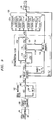
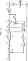
- FIG. 9 illustrates a receiver that is used with the present invention.
- a signal is received from local loop 24 through hybrid 64.
- the receive signal then passes through linear equalizer 100.
- Demodulator/linear Equalizer 100 is well known in the industry.
- the signal then passes into noise whitening filter 102.
- Noise whitening filter 102 compensates for colored noise that is introduced by the communication channel. It is desirable to have white noise so that the trellis code can be successfully decoded.
- Noise whitening filter 102 comprises three-tap FIR filter 104 and summer 106.
- FIR filter 104 is well known in the industry and has the same tap values as FIR filter 66 in the remote transmitter of FIG. 3.
- the whitened signal r(k) is fed to trellis decoder 108.
- Trellis decoder 108 executes the well known Viterbi algorithm to recover the trellis code and bits I1 - I n .
- the recovered trellis code is used to identify the transmitted constellation subset. This information is supplied to enhancement unit 110 of reconstruction filter 112.
- Trellis enhancement unit 110 also receives the x-cnt and y-cnt outputs of modulo device 114.
- the output of trellis decoder 108 is signal y'(k) and represents a signal having an expanded number of symbols or signal points that extend beyond the constellation of FIG. 4.
- Constellation expansion is a result of noise whitening filter 102 and its complementary filter and modulo device in the remote transmitter.
- FIR filter 116 and summer 118 operate to perform the inverse of noise whitening filter 102.
- the coefficients of 3 tap FIR filter 116 are the same as FIR filters 104 and 66 in the remote transmitter.
- the output of FIR filter 116 is labeled p' (k) and is fed to modulo device 114. Modulo device 114 operates in the same manner as the remote modulo device 54.
- modulo device 114 produces signals x-cnt and y-cnt.
- the output of modulo device 114 is signal d' (k) which is an estimate of signal d(k).
- Signal d' (k) is combined with signal x' (k) from summer 118 in summer 120.
- the output of summer 120 is signal e' (k).
- the output of summer 120 is fed to slicers 122a, b, c and d, and slicers 124a, b, c and d.
- Slicers 122a, b, c and d and slicers 124a, b, c and d are used to determine which symbol of constellation subsets a, b, c, d, and A, B, C and D, respectively, are represented by signal e' (k).
- Mux 126 is used to select the output of one of the aforementioned slicers. Mux 126 is controlled using trellis enhancement unit 110.
- Trellis enhancement unit 110 uses the bits Y ' 0 -Y ' n to identify the transmitted constellation subset, and inputs x-cnt and y-cnt of modulo device 114 are used in accordance with Table 2 to identify the original constellation subset that was replaced with the transmitted subset. Once the original subset has been identified, the slicer associated with that subset is selected using mux 126. The output of mux 126 is then fed to parallel-to-serial converter 128 to recover the originally provided data stream.
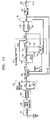
- FIG. 10 illustrates an alternative embodiment for selecting substitute constellation subsets in the transmitter.
- mappers 44a, b, c, d and 46a, b, c, d are replaced with mappers 140 and 142.
- Each mapper maps signal containing bits I n+1 to I1 into a constellation subset.
- mux 144 selects one of the two groups of four subsets. A particular subset within a group of four is selected through the use of multiplier 146.
- the subset from mux 144 can be rotated by 0, 90, 180 or 270 degrees to produce any one of the four subsets associated with each mapper.
- trellis enhancement device 52 has two outputs, one output selects between mapper 140 and 142 using mux 144, and the other output indicates to multiplier 146 that a 0, 90, 180 or 270 degree phase shift should be initiated. This operation provides the advantage of using a smaller number of mappers as compared to the embodiment of FIG. 3.
- FIG. 11 illustrates an alternative embodiment of the receiver shown in FIG. 9.
- Signal e' (k) is received by multiplier 150, the output of multiplier 150 is fed to slicers 152 and 154. The output of slicers 152 and 154 are selected using mux 156.
- Trellis enhancement unit 110 provides inputs to multiplier 150 and mux 156.
- trellis enhancement unit 110 uses the received subset identity from trellis decoder 108, and the x-cnt and y-cnt inputs from modulo device 114 to identify the original constellation subset.
- multiplier 150 is used to rotate the received symbol by 0, 90, 180 or 270 degrees to reverse the effect of multiplier 146.
- Mux 156 is used to pick the appropriate slicer output to recover the original data.
- FIGS. 12 and 13 illustrate another embodiment of the present invention.
- the transmitter is modified by placing preprocessing unit 200 between serial-to-parallel converter 40, and mappers 140 and 142.
- the processor can be used to perform functions such as fractional rate encoding, modulus conversion, shaping by rings, and constellation switching. Additionally, the output of summer 58 is fed to non-linear encoder 300 before being passed to modulator 60.
- the receiver has been modified to include nonlinear decoder 400 between demodulator/linear equalizer 100 and noise whitening filter 102.
- Non-linear decoder 400 compensates for the action of non-linear encoder 300.
- post-processing unit 202 is placed between mux 156 and parallel-to-serial converter 128. Post-processing unit 202 forms the inverse of preprocessing unit 200.
- the non-linear encoder compensates for non-linear characteristics of the transmission channel.
- the non-linear encoder warps the constellation by adjusting the positions of its signal points in accordance with a warp function which models the inverse of that component of the non-linear characteristic of the transmission channel which is known a priori.
- that component is typically a logarithmic function of the magnitude of the signal being transmitted--the so-called ⁇ -law characteristic.
- an inverse logarithmic function i.e., an exponential function, of the magnitude of the transmitted signal is used to warp the constellation.
- the receiver can "unwarp" the received signal points prior to applying them to the Viterbi decoder using the inverse of the warp function and thereby modeling the known non-linear component of the channel characteristic.
- the inverse function is the inverse of the ⁇ -law characteristic and is, more particularly, a logarithmic function.
- the Viterbi decoder can use the standard, unmodified Viterbi decoding algorithm.
- the X and Y orthogonal values in signal x(k) are warped by being multiplied by a warp multiplier w generated in accordance with a selected warp function.
- the warp multiplier is generated by encoder 202, which provides it on lead 304 to multipliers 306 and 308. The latter carry out the aforementioned multiplication and the resulting warped values are applied to modulator 60 which, in standard fashion, generates a modulated line signal representing the stream of warped signal points.
- the communication channel includes a PCM system so that the overall channel characteristic has a known non-linear component which is a function of instantaneous signal magnitude, that function being the ⁇ -law characteristic.
- the warp function used by encoder 302 to generate warp multiplier w is a function of the signal magnitude of the transmitted signal points. That is, the magnitude is an independent variable in the warp function.
- warp generator 316 that value of p t is then applied to warp generator 316, which receives a warp factor g on lead 318 from within the modem or communication device.
- This factor--which is another independent variable in the warp function-- is selected as a function of the degree to which it is desired to warp the overall signal constellation which, in turn, is a function of the known component of the non-linear characteristic of the channel--in this case, the ⁇ -law characteristic.
- preliminary warp multiplier w' is processed within encoder 302 by automatic gain control (AGC) 320 to generate the aforementioned warp multiplier w on lead 304.
- AGC automatic gain control
- the AGC has a very long time constant, thereby providing a scaling function which, after an adaptation period, will be essentially constant for any given constellation and warp factor g . This serves to impose an upper limit on the value of warp multiplier w which avoids any exceeding of the channel power limits.
- FIGS. 15-17 show the warped versions of the constellation of FIG. 18 that result from the warping just described using different values of warp factor g .
- the particular value of warp factor g that is used will depend on the application and may be determined empirically. In any case, it will be appreciated that each of the warped signal points of the constellation of FIGS. 15-17 are related to a respective signal point of the base constellation of FIG. 18 in accordance with a predetermined warp function.
- the signal from demodulator/linear equalizer 100 represents the demodulator/equalizer's best estimate of the in-phase and quadrature-phase components of the transmitted signal points, designated X r and Y r , the subscript "r" denoting "receiver.”
- These components are "unwarped,” by non-linear decoder 400 by multiplying them by an unwarping multiplier W .
- that multiplier is generated by decoder 402, which provides multiplier W on lead 404 to multipliers 406 and 408 in a manner described below.
- Multipliers 406 and 408 carry out the aforementioned multiplication, and the resulting unwarped in-phase and quadrature-phase values on leads 410 and 412 are applied to noise whitening filter 102.
- decoder 402 its job is to determine the value of p r of the received signal points and, armed with a knowledge of the value of warp factor g , to perform the inverse of the warping that was undertaken in the transmitter.
- the value of the magnitude p r that is used in the expression for unwarp multiplier W is the value computed from the received signal points. This value of p r will typically be at least a little different from the value used to generate warp multipler w in the transmitter owing to the noise component superimposed on the received signal points. This means that the amount by which a point is unwarped will be slightly different than the amount by which it was warped.
- this difference will tend to bring the signal points, upon being unwarped, into tighter loci about their corresponding positions in the base constellation than if, for example, the unwarping were to be carried out employing the value of p t used in the transmitter (assuming that value could, in fact, be made known to, or could be computed in, the receiver).
- the foregoing relates to noise that was superimposed on the transmitted signal points after the ⁇ -law encoding in the channel has been carried out.
- the transmitted signal points have already been somewhat perturbed due to noise and other channel effects occurring between the transmitter and the codec within the channel in which the ⁇ -law encoding is actually carried out.
- the warped signal points are not warped from the ideal signal point positions of FIG. 18, but rather from positions that are just a little bit displaced therefrom.
- Using the inverse of the ⁇ -law characteristic in the receiver does not take account of this. The effect is very minor, so that the approach described hereinabove does work quite well. It is, however, possible to take account of that effect, thereby providing results that are even better.
- n a 2 p 2 + b 2
- n the root-mean-square (r.m.s.) value of the noise associated with a signal point of magnitude p .
- the constants a and b depend upon the properties of the communication channel and the transmit and receive filters.
- the warp function and its inverse to be such that, upon warping, the distance between adjacent signal points is proportional to the r.m.s. noise associated with those points.
- the original constellation with equal spacing of signal points is approximately restored, with approximately equal noise power associated with each signal point.
- warp factor g can be pre-set in the transmitter and receiver based on the expected characteristics of the channel.
- one might adaptively determine g by having the receiver examine the dispersion of the received signal points about the expected signal points and then use that measurement to adapt the value of g in the receiver while making that value known to the transmitter via, for example, conventional diagnostic channel communications between the two modems or communication devices.
- the invention is disclosed in the context of a system using two-dimensional constellations. However, it is equally applicable to systems using constellations of any dimensionality, as will be well appreciated by those skilled in the art.
- the invention is not limited to modem technology but rather to any type of signal transmission system and/or environment in which inter-symbol intereference and/or deterministic, non-linear effects are present.
Landscapes
- Engineering & Computer Science (AREA)
- Computer Networks & Wireless Communication (AREA)
- Signal Processing (AREA)
- Physics & Mathematics (AREA)
- Spectroscopy & Molecular Physics (AREA)
- Power Engineering (AREA)
- Digital Transmission Methods That Use Modulated Carrier Waves (AREA)
Abstract
Description
- The invention relates to encoding data for transfer over a communication channel; more specifically, communicating data over a telephone communication channel which is susceptible to inter-symbol interference.
- U.S. Patent 5,162,812, entitled "Technique for Achieving the Full Coding Gain of Encoded Digital Signals", discloses a system in which a transmitted signal is encoded using a trellis code and precoded using a generalized partial response filter. FIG. 1 illustrates the transmitter disclosed in the aforementioned U.S. Patent. Serial-to-
parallel converter 10 converts the incoming data to parallel words. Trellisencoder 12 encodes the parallel word to provide increased immunity to inter-symbol interference.Symbol mapper 14 maps the trellis encoded word to a signal point in a predefined symbol or signal point constellation. The symbol specified bysymbol mapper 14 is in the form of a complex number which is received byprecoding unit 16.Precoding unit 16 is used to compensate for signal distortions that are introduced at a receiver when the receiver passed the symbol through a noise whitening filter. Received symbols are passed through a noise whitening filter to compensate for the communication channel's colored noise and thereby improve proper decoding of the trellis code.Precoder 16 includestransversal filter 18 andnon-linear filter 20.Non-linear filter 20 is in the form of a modulo device that repeatedly subtracts or adds a value of 2L until the output a of the device satisfies -L ≦ α ≦L. Non-linear filter 20 is used to compensate for any instability introduced byfilter 18. The output ofencoder 16 is modulated bymodulator 19 using a modulation technique such as QAM (quadrature amplitude modulation). The output ofmodulator 19 is filtered byfilter 20, passed throughhybrid 22, and then out tolocal telephone loop 24. - A similar system is disclosed in a paper presented to Technical Committee TR-30 of the Telecommunications Industry Association (TIA) in Atlanta, Georgia on April 15, 1993. The paper is entitled "Implementation of Precoding in V-FAST" authored by Eyuboglu et al. FIG. 2 illustrates the precoder disclosed in the paper.
Precoder 30 is similar toprecoder 16. In this embodiment both the FIR filter and the modulo device are in the feedback loop. The FIR filter is disclosed as a 3-tap filter and the output of the modulo device is subtracted from the input to the precoder. - Both of the aforementioned systems precode the data so that there is compensation for the effects of the noise whitening filter in the receiver. Unfortunately, both systems have drawbacks. The first system is only useful for square symbol constellations and thereby prevents using more efficient constellations. The second system uses a relatively large dither signal. The large dither signal varies transmitted signal power by a relatively large amount that may exceed the maximum allowable power for the communication channel. As a result, the amount of signal space allotted to the constellation must be decreased to accommodate the variations in transmitted power. Decreasing the constellation's signal space decreases the space between signal points in the constellation and decreases noise immunity.
- The present invention is not limited to square constellations and it decreases the amplitude of the dither signal. The dither signal is decreased by using a smaller modulo value to generate the dither signal while maintaining the ability to recover the original trellis code in the receiver. The recoverability of the original trellis code is achieved by using a modulo count, which was formed while producing the dither signal, to select a substitute constellation subset for the constellation subset identified by the trellis encoder.
-
- FIG. 1 illustrates a prior art transmitter,
- FIG. 2 illustrates a precoder used in a transmitter;
- FIG. 3 illustrates the transmitter section of one embodiment of the present invention;
- FIG. 4 illustrates a symbol or signal point constellation;
- FIG. 5 illustrates a state machine with 64 states;
- FIG. 6 illustrates a state machine with 16 states;
- FIG. 7 is a subset selection table;
- FIG. 8 is a subset substitution table;
- FIG. 9 illustrates the receiver section of one embodiment of the present invention;
- FIG. 10 illustrates the transmitter section of another embodiment of the present invention;
- FIG. 11 illustrates the receiver section of another embodiment of the present invention;
- FIG. 12 illustrates the transmitter section of the present invention with a non-linear encoder;
- FIG. 13 illustrates the receiver section of the present invention with a non-linear decoder;
- FIG. 14 is a block diagram of the non-linear encoder;
- FIGS. 15-17 illustrate warped constellations with different values for g;
- FIG. 18 illustrates an unwarped constellation; and
- FIG. 19 is a block diagram of the non-linear decoder.
- FIG. 3 illustrates the transmitter section of one embodiment of the present invention. Serial data is received by serial-to-
parallel converter 40. The output of serial-to-parallel converter 40 is an L-bit word.Bits 1 to n are sent todifferential encoder 42, and the remaining n+1 to L bits are sent to symbol mappers 44a, 44b, 44c, 44d, and 46a, 46b, 46c and 46d. Bits n+1 to L are mapped into different signal point or symbol constellation subsets by the mappers. Taken together, the subsets comprise the overall transmit constellation. The output of each mapper is a complex number with orthogonal components. The complex number identifies a symbol in a symbol constellation subset. The outputs from mappers are received bymux 48. -
Differential encoder 42 differentially encodes some ofbits 1 through n. Differentially encoded bits, as well as the unchanged data bits, are passed totrellis encoder 50. Trellisencoder 50 produces trellis bits Y₀ through Yn. Bits Y₀ through Yn are received bytrellis enhancer 52. Trellisenhancer 52 also receives inputs x-count and y-count frommodulo device 54. Based on the values Y₀-Yn, and the values of x-count and y-count, trellis enhanced controls mux 48 to select one of the mapper outputs. The output ofmux 48, signal e(k), is received bysummer 58. Dither signal d(k) from modulodevice 54 is subtracted from signal e(k) insummer 58. The output ofsummer 58, signal x(k), is fed tomodulator 60,passband filter 62 andhybrid 64. The output ofsummer 58 is also fed to three-tap finite impulse response (FIR)filter 66. The output offilter 66 is received by modulodevice 54 to produce outputs x-count, y-count and d(k). - During each symbol period, serial-to-
parallel converter 40 produces parallel word (I₁-IL)k. Bits In+1-IL are passed to the mappers. The mappers output a signal point or symbol in a predefined constellation subset based on bits In+1 - IL. FIG. 4 illustrates an 8-way partitioned symbol constellation. Bits I₁-IL are encoded as one of the symbols in the constellation. The constellation shows that there are eight constellation subsets making up the overall constellation. The subsets consist of signal points labeled a, b, c, d, A, B, C and D, where like letters belong to the same subset. In a 4-way partitioned constellation where there are four subsets, the upper and lower case form of each letter is considered part of the same subset. Data bits I₁ through In and a trellis bit are used to select one of the eight subsets. Data bits In+1 through IL are used to identify a particular symbol or signal point within the subset. -
Differential encoder 42 andtrellis encoder 50 use bits I₁ - In to choose a constellation subset. In this embodiment n=5; however, it may have other values.Differential encoder 40 differentially encodes bits I₂ - I₃ in accordance with the differential encoding table to produce bits J₂ and J₃.
Bits I₁,J₂,J₃,I₄ and I₅ are fed totrellis encoder 50.Trellis encoder 50 can be any finite state machine. These types of state machines are well known in the art and two such state machines are shown in FIGS. 5 and 6. The state machine of FIG. 5 is a 64-state machine and the state machine of FIG. 6 is a 16-state machine. State machines with other numbers of states may be used. In the case of the 64-state machine, bits J₂,I₁,J₃ and I₄ are used as inputs. The outputs of the state machine are bits Y₀-Y₅, where bits Y₁-Y₅ equal bits I₁,J₂,J₃,I₄ and I₅, respectively. The devices labeled 80 are adders and the devices labeled 82 are delays. Bits Y₀-Y₅ are used to identify constellation subsets that are used with remaining bits In+1-IL. The state machines of FIGS. 5 and 6 are used to output a new Y₀ bit every symbol period for two-dimensional trellis encoding, and every other symbol period for 4-dimensional encoding. If a new set of outputs is produced each symbol period, delayelements 82 act as a one-symbol period delay, and if a new output is produced every other symbol period,elements 82 act as two symbol period delays. When used to produce a new set of outputs Y₀ through Y₅ every two symbol periods, the selection of subsets is shown in Table 1 of FIG. 7. The Table illustrates which constellation subsets will be used during the two symbol periods. The first letter identifies the constellation subset used during the first symbol period, and the second letter identifies the constellation subset used during the second symbol period. (If two-dimensional encoding is used, only the first letter is used.) For example, if Y₀ throughY ₅ equal 000010, bits (In+1-IL)k-1 will be encoded using constellation subset "a" and bits (In+1-IL)k will be encoded using constellation subset "A". - If a constellation with a 4-way partition is used, the 16-state machine of FIG. 6 is used to produce bits Y₀ - Y₃. (In this case, n=3), where bits Y₁, Y₂ and Y₃ equal bits I₁,J₂ and J₃, respectively. Table 1 is used with Y₄ and Y₅ set equal to 0, and with lower and upper case forms of the same letter belonging to the same constellation subset.
- It is also possible to practice the present invention without the use of the encoders of FIGS. 5 or 6. In this case, n=2 and bits I₁ and I₂ are fed to the differential encoder. the J₂ and J₃ bits from the differential encoder are used as bits Y₂ and Y₃. In this embodiment, two-dimensional coding is used and the differential encoder produces a new output for each symbol period. Table 1 is used with Y₀, Y₁, Y₄ and Y₅ set equal to 0, and with the second letter in each table entry ignored.
- Returning to the case of an 8-way partitioned constellation, mappers 44a through 44d, and 46a through 46d, identify a symbol in constellation subsets a, b, c, d and A, B, C, D, respectively, based on bits In+1-IL. The desired mapper output is selected using
mux 48 which is controlled bytrellis enhancer 52. -
Trellis enhancer 52 substitutes the constellation subset identified by Table 1 and bits Y₀ through Yn (in this example n = 5), based on the value of x-cnt and y-cnt from modulodevice 54. Table 2 of FIG. 8 illustrates the subset substitutions.Trellis enhancer 52 operatesmux 48 in accordance with Table 2 so that the proper substitution occurs. The output ofmux 48 is received bysummer 58. - Before
trellis enhancer 52 substitutes a constellation subset for the one identified by bits Y₀ - Yn,FIR filter 66 computes output p(k) based on its memory of past transmitted symbols (in the case of a 3-tap filter, the past three symbols).FIR filter 66 is a 3-tap filter that is well known in the art. Coefficients for the filter are obtained during training in a manner well known in the art and specified by standards committees such as the ITU (International Telecommunication Union, formerly the CCITT) in ITU Recommendation V.32bis. The output of the FIR filter is received by modulodevice 54. Modulodevice 54 performs a modulo operation on each of the orthogonal components of the symbol to produce a separate modulo count, x-cnt and y-cnt, for the X and Y orthogonal components of filter 68's output. If the output of the FIR filter is positive and greater than 2-m for a particular orthogonal component of p(k), then modulo value 2(2-m) is subtracted an integral number of times from that component of p(k) until the result is less than or equal to 2-m. The number of subtractions is counted by incrementing a respective x or y counter. If the output of the FIR filter is negative and less than or equal to - 2-m for a particular orthogonal component of p(k), then modulo value 2(2-m) is added an integral number of times to that component of p(k) until the result is greater than or equal to -2-m. The number of additions is counted by decrementing the respective x or y counter. The counters arearithmetic base 4; that is, decrementing two-bit value 00 by 1 produces two-bit value 11, and incrementing two-bit value 11 by 1 produces two-bit value 00. These counts are provided totrellis enhancer 52 via lines x-cnt and y-cnt. The portion of signal p(k) that remains after these subtractions/additions is provided tosummer 58 as signal d(k). Signal d(k) is called the dither signal. After performing these calculations,trellis enhancer 52 uses x-cnt, y-cnt and bits Y₀ through Yn to substitute constellation subsets in accordance with Table 2. (For 4-way partitioned constellations, upper and lower case versions of the same letter are considered identical and only the first four columns of Table 2 are necessary.) The resulting output frommux 48 is sent tosummer 58 where value d(k) is subtracted to produce signal x(k). This signal is provided tomodulator 60,filter 62 andhybrid 64 in a conventional manner. - The count of additions or subtractions is computed independently for each orthogonal axis of the output from
filter 66. The counts can be maintained usingarithmetic base 4 for 8-way partition constellations andarithmetic base 2 for 4-way partition constellations. These counts are used by thetrellis enhancer 52 to perform the substitutions in accordance with Table 2. - When using large symbol constellations, a larger dither signal is tolerable because the larger dither signal reduces error propagation in the receiver's reconstruction filter. In order to accommodate a variety of constellations it may be desirable to use a variable modulo device. A variable modulo device performs similarly to modulo
device 54 with the following differences. If the output of the FIR filter is positive and greater than K2-m for a particular orthogonal component of p(k), then modulo value 2K(2-m) is subtracted an integral number of times from that component of p(k) until the result is less than or equal to K2-m. The number of subtractions is counted by incrementing a respective x or y counter K times the number of subtractions. If the output of the FIR filter is negative and less than or equal to -K2-m for a particular orthogonal component of p(k), then modulo value 2K(2-m) is added an integral number of times to that component of p(k) until the result is greater than or equal to -K2-m. The number of additions is counted by decrementing the respective x or y counter K times the number of additions. The variable K is an integer that is greater than 1 for large constellations and equal to 1 for small constellations. - With regard to the
value 2-m, and in reference to FIG. 4, the spacing between symbols is shown to be 2x2-m. Thevalue 2-m is an arbitrary scaler where m is preferably an integer such as 7 or 8. - FIG. 9 illustrates a receiver that is used with the present invention. A signal is received from
local loop 24 throughhybrid 64. The receive signal then passes throughlinear equalizer 100. Demodulator/linear Equalizer 100 is well known in the industry. The signal then passes intonoise whitening filter 102.Noise whitening filter 102 compensates for colored noise that is introduced by the communication channel. It is desirable to have white noise so that the trellis code can be successfully decoded.Noise whitening filter 102 comprises three-tap FIR filter 104 andsummer 106.FIR filter 104 is well known in the industry and has the same tap values asFIR filter 66 in the remote transmitter of FIG. 3. The whitened signal r(k) is fed totrellis decoder 108.Trellis decoder 108 executes the well known Viterbi algorithm to recover the trellis code and bits I₁ - In. The recovered trellis code is used to identify the transmitted constellation subset. This information is supplied toenhancement unit 110 ofreconstruction filter 112.Trellis enhancement unit 110 also receives the x-cnt and y-cnt outputs of modulodevice 114. - The output of
trellis decoder 108 is signal y'(k) and represents a signal having an expanded number of symbols or signal points that extend beyond the constellation of FIG. 4. Constellation expansion is a result ofnoise whitening filter 102 and its complementary filter and modulo device in the remote transmitter. To eliminate this expansion,FIR filter 116 andsummer 118 operate to perform the inverse ofnoise whitening filter 102. The coefficients of 3tap FIR filter 116 are the same as FIR filters 104 and 66 in the remote transmitter. The output ofFIR filter 116 is labeled p' (k) and is fed to modulodevice 114. Modulodevice 114 operates in the same manner as the remote modulodevice 54. As was described with regard to modulodevice 54, modulodevice 114 produces signals x-cnt and y-cnt. The output of modulodevice 114 is signal d' (k) which is an estimate of signal d(k). Signal d' (k) is combined with signal x' (k) fromsummer 118 insummer 120. The output ofsummer 120 is signal e' (k). The output ofsummer 120 is fed to slicers 122a, b, c and d, and slicers 124a, b, c and d. Slicers 122a, b, c and d and slicers 124a, b, c and d are used to determine which symbol of constellation subsets a, b, c, d, and A, B, C and D, respectively, are represented by signal e' (k).Mux 126 is used to select the output of one of the aforementioned slicers.Mux 126 is controlled usingtrellis enhancement unit 110.Trellis enhancement unit 110 uses the bits Y

device 114 are used in accordance with Table 2 to identify the original constellation subset that was replaced with the transmitted subset. Once the original subset has been identified, the slicer associated with that subset is selected usingmux 126. The output ofmux 126 is then fed to parallel-to-serial converter 128 to recover the originally provided data stream. - FIG. 10 illustrates an alternative embodiment for selecting substitute constellation subsets in the transmitter. In this embodiment mappers 44a, b, c, d and 46a, b, c, d are replaced with
mappers mapper mux 144 selects one of the two groups of four subsets. A particular subset within a group of four is selected through the use ofmultiplier 146. The subset frommux 144 can be rotated by 0, 90, 180 or 270 degrees to produce any one of the four subsets associated with each mapper. As a result,trellis enhancement device 52 has two outputs, one output selects betweenmapper mux 144, and the other output indicates tomultiplier 146 that a 0, 90, 180 or 270 degree phase shift should be initiated. This operation provides the advantage of using a smaller number of mappers as compared to the embodiment of FIG. 3. - In a similar manner, FIG. 11 illustrates an alternative embodiment of the receiver shown in FIG. 9. Signal e' (k) is received by
multiplier 150, the output ofmultiplier 150 is fed toslicers slicers mux 156.Trellis enhancement unit 110 provides inputs tomultiplier 150 andmux 156. As discussed with regard to FIG. 9,trellis enhancement unit 110 uses the received subset identity fromtrellis decoder 108, and the x-cnt and y-cnt inputs from modulodevice 114 to identify the original constellation subset. As discussed with regard to FIG. 10,multiplier 150 is used to rotate the received symbol by 0, 90, 180 or 270 degrees to reverse the effect ofmultiplier 146.Mux 156 is used to pick the appropriate slicer output to recover the original data. - FIGS. 12 and 13 illustrate another embodiment of the present invention. With regard to FIG. 12, the transmitter is modified by placing
preprocessing unit 200 between serial-to-parallel converter 40, andmappers summer 58 is fed tonon-linear encoder 300 before being passed tomodulator 60. - With regard to FIG. 13, the receiver has been modified to include
nonlinear decoder 400 between demodulator/linear equalizer 100 andnoise whitening filter 102.Non-linear decoder 400 compensates for the action ofnon-linear encoder 300. In addition,post-processing unit 202 is placed betweenmux 156 and parallel-to-serial converter 128.Post-processing unit 202 forms the inverse ofpreprocessing unit 200. - The non-linear encoder compensates for non-linear characteristics of the transmission channel. The non-linear encoder warps the constellation by adjusting the positions of its signal points in accordance with a warp function which models the inverse of that component of the non-linear characteristic of the transmission channel which is known a priori. In the case of a PCM system, for example, that component is typically a logarithmic function of the magnitude of the signal being transmitted--the so-called µ-law characteristic. Thus, an inverse logarithmic function, i.e., an exponential function, of the magnitude of the transmitted signal is used to warp the constellation.
- Because the constellation warping is deterministic, it is possible for the receiver to "unwarp" the received signal points prior to applying them to the Viterbi decoder using the inverse of the warp function and thereby modeling the known non-linear component of the channel characteristic. (In the case of a PCM system, the inverse function is the inverse of the µ-law characteristic and is, more particularly, a logarithmic function.) As a result, the Viterbi decoder can use the standard, unmodified Viterbi decoding algorithm.
- In reference to FIG. 14, the X and Y orthogonal values in signal x(k) are warped by being multiplied by a warp multiplier w generated in accordance with a selected warp function. Specifically, the warp multiplier is generated by
encoder 202, which provides it onlead 304 tomultipliers 306 and 308. The latter carry out the aforementioned multiplication and the resulting warped values are applied tomodulator 60 which, in standard fashion, generates a modulated line signal representing the stream of warped signal points. - It is presumed that the communication channel includes a PCM system so that the overall channel characteristic has a known non-linear component which is a function of instantaneous signal magnitude, that function being the µ-law characteristic. Accordingly, the warp function used by
encoder 302 to generate warp multiplier w is a function of the signal magnitude of the transmitted signal points. That is, the magnitude is an independent variable in the warp function. To this end,encoder 302 includesmagnitude computer 310, which receives the X and Y values fromleads 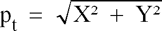
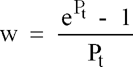
generator 316, which receives a warp factor g onlead 318 from within the modem or communication device. This factor--which is another independent variable in the warp function--is selected as a function of the degree to which it is desired to warp the overall signal constellation which, in turn, is a function of the known component of the non-linear characteristic of the channel--in this case, the µ-law characteristic. In the present illustrative embodiment,warp generator 316 generates a preliminary warp multiplier w' in accordance with the warp function
where P t = p t/g. - This relation is a series approximation to the (exponential) inverse of the µ-law characteristic
Moreover, where a different non-linear relationship obtains in the channel, a different inverse of that function would be used bywarp generator 316. For example, if the channel includes an ADPCM system, where the signal processing algorithm changes over time, as a function of signal magnitude, then the value of g used bywarp generator 316 would be adapted in such a way as to model the inverse of that algorithm. The function used by the warp generator could also take into account how one expects noise in the channel to differently affect low- and high-magnitude signal points of the constellation. - Depending on the value of warp factor g and the range of values for p t , it may be the case that multiplying preliminary warp multiplier w' by X and Y would result in warped signal points that cause the peak and/or average power limits of the channel to be exceeded. Accordingly, preliminary warp multiplier w' is processed within
encoder 302 by automatic gain control (AGC) 320 to generate the aforementioned warp multiplier w onlead 304. The AGC has a very long time constant, thereby providing a scaling function which, after an adaptation period, will be essentially constant for any given constellation and warp factor g. This serves to impose an upper limit on the value of warp multiplier w which avoids any exceeding of the channel power limits. - FIGS. 15-17 show the warped versions of the constellation of FIG. 18 that result from the warping just described using different values of warp factor g. The particular value of warp factor g that is used will depend on the application and may be determined empirically. In any case, it will be appreciated that each of the warped signal points of the constellation of FIGS. 15-17 are related to a respective signal point of the base constellation of FIG. 18 in accordance with a predetermined warp function.
- Turning, now, to the receiver of FIG. 13, and in reference to FIG. 19, the signal from demodulator/
linear equalizer 100 represents the demodulator/equalizer's best estimate of the in-phase and quadrature-phase components of the transmitted signal points, designated Xr and Yr, the subscript "r" denoting "receiver." These components are "unwarped," bynon-linear decoder 400 by multiplying them by an unwarping multiplier W. Specifically, that multiplier is generated bydecoder 402, which provides multiplier W onlead 404 tomultipliers Multipliers leads noise whitening filter 102. - Referring to
decoder 402, its job is to determine the value of p r of the received signal points and, armed with a knowledge of the value of warp factor g, to perform the inverse of the warping that was undertaken in the transmitter. Thus,decoder 402 includesmagnitude computer 414, which computes the value of p r from the received Xr and Yr values onleads unwarp generator 420 which, responsive to the value of warp factor g onlead 422, generates unwarp multiplier W in accordance with the relation
where P r = p r/g. - This is the inverse of the relation by which preliminary warp multiplier w' was generated and is a series approximation--usable for P r < 1--to the (logarithmic) µ-law characteristic

For P r ≧ 1, a different approximation would be used. - Note that the value of the magnitude p r that is used in the expression for unwarp multiplier W is the value computed from the received signal points. This value of p r will typically be at least a little different from the value used to generate warp multipler w in the transmitter owing to the noise component superimposed on the received signal points. This means that the amount by which a point is unwarped will be slightly different than the amount by which it was warped. Advantageously, however, this difference will tend to bring the signal points, upon being unwarped, into tighter loci about their corresponding positions in the base constellation than if, for example, the unwarping were to be carried out employing the value of p t used in the transmitter (assuming that value could, in fact, be made known to, or could be computed in, the receiver).
- The foregoing relates to noise that was superimposed on the transmitted signal points after the µ-law encoding in the channel has been carried out. However, at the point in time that they are subjected to the µ-law encoding in the channel, the transmitted signal points have already been somewhat perturbed due to noise and other channel effects occurring between the transmitter and the codec within the channel in which the µ-law encoding is actually carried out. Thus the warped signal points are not warped from the ideal signal point positions of FIG. 18, but rather from positions that are just a little bit displaced therefrom. Using the inverse of the µ-law characteristic in the receiver does not take account of this. The effect is very minor, so that the approach described hereinabove does work quite well. It is, however, possible to take account of that effect, thereby providing results that are even better.
- In particular, it is known that, in the absence of warping, the noise associated with each received signal point--due to the non-linear A/D converter in a PCM system--may be closely represented by an equation of the form

where n is the root-mean-square (r.m.s.) value of the noise associated with a signal point of magnitude p. The constants a and b depend upon the properties of the communication channel and the transmit and receive filters. - In situations, such as that postulated here, in which the transmission channel superimposes multiplicative noise onto the received signal points, it is advantageous for the warp function and its inverse to be such that, upon warping, the distance between adjacent signal points is proportional to the r.m.s. noise associated with those points. As a result, the noise superimposed on each received signal point is independent of its position in the constellation and the difference of error probabilities associated with different signal points is minimized. If the constellation contains a large number of signal points, this property is achieved by a warp function

where P t = p t/g and g = b/a. - This relation is a series approximation to a hyperbolic sine function

Since the value of a and b are dependent on the communication channel and are generally not known a priori, g may be adapted as before, or may be calculated from measurement of the received noise so as to determine the ratio b/a. - The corresponding receiver unwarp multiplier is generated according to the relation

which is a series approximation to the inverse hyperbolic sine function
valid for P r < 1. - After the unwarping operation is carried out, the original constellation with equal spacing of signal points is approximately restored, with approximately equal noise power associated with each signal point.
- The foregoing merely illustrates the principles of non-linear encoding/decoding. Thus, although logarithmic and sinh functions are discussed herein, other functions may be advantageous in particular circumstances.
- In a simple implementation, warp factor g can be pre-set in the transmitter and receiver based on the expected characteristics of the channel. In a more sophisticated application, one might adaptively determine g by having the receiver examine the dispersion of the received signal points about the expected signal points and then use that measurement to adapt the value of g in the receiver while making that value known to the transmitter via, for example, conventional diagnostic channel communications between the two modems or communication devices.
- Although the various functional blocks of the transmitter and receiver are shown for pedagogic clarity as individual discrete elements, the functions of those blocks could and, with present technology, typically would be carried out by one or more programmed processors, digital signal processing (DSP) chips, etc., as is well known to those skilled in the art.
- The invention is disclosed in the context of a system using two-dimensional constellations. However, it is equally applicable to systems using constellations of any dimensionality, as will be well appreciated by those skilled in the art.
- It is also important to note that the invention is not limited to modem technology but rather to any type of signal transmission system and/or environment in which inter-symbol intereference and/or deterministic, non-linear effects are present.
- Thus it will be appreciated that many and varied arrangements may be devised by those skilled in the art which, although not explicitly shown or described herein, embody the principles of the invention and are thus within its spirit and scope.
Claims (6)
- A method of transmitting data over a communication channel, characterized by the steps of:
identifying a first signal point from a predefined signal point constellation based on a data word;
generating a first signal using at least one prior transmitted signal point;
selecting a second signal point from said predefined signal point constellation based on said first signal point and a modulo count derived from said first signal; and
transmitting a signal representative of said second signal point over the communication channel. - The method of claim 1, characterized in that said step of identifying a first signal point comprises basing said identification on said data word and a current state of a state machine, said current state of said state machine being a function of at least one bit of said data word.
- The method of claim 1, characterized in that said modulo count comprises conducting a separate modulo count on each orthogonal component of said first signal.
- The method of claim 1, characterized in that a variable modulo value is used to produce said modulo count.
- The method of claim 1, further characterized by adding a dither signal to said second signal point.
- The method of claim 1, characterized in that said dither signal comprises orthogonal components X and Y, where -2-m≦ X ≦2-m, -2-m≦ Y ≦2-m, and 2(2-m) is the distance between adjacent signal points in said signal point constellation.
Applications Claiming Priority (2)
| Application Number | Priority Date | Filing Date | Title |
|---|---|---|---|
| US9350893A | 1993-07-16 | 1993-07-16 | |
| US93508 | 1993-07-16 |
Publications (3)
| Publication Number | Publication Date |
|---|---|
| EP0634856A2 true EP0634856A2 (en) | 1995-01-18 |
| EP0634856A3 EP0634856A3 (en) | 1995-05-31 |
| EP0634856B1 EP0634856B1 (en) | 2001-11-14 |
Family
ID=22239346
Family Applications (1)
| Application Number | Title | Priority Date | Filing Date |
|---|---|---|---|
| EP94304979A Expired - Lifetime EP0634856B1 (en) | 1993-07-16 | 1994-07-06 | Nonlinear coding for channels with intersymbol interference |
Country Status (5)
| Country | Link |
|---|---|
| US (1) | US5559835A (en) |
| EP (1) | EP0634856B1 (en) |
| JP (1) | JP3595574B2 (en) |
| CA (1) | CA2124376A1 (en) |
| DE (1) | DE69429037T2 (en) |
Cited By (10)
| Publication number | Priority date | Publication date | Assignee | Title |
|---|---|---|---|---|
| EP0768781A3 (en) * | 1995-10-10 | 1997-05-02 | AT&T Corp. | Apparatus for high-speed simultaneous voice/data communications |
| FR2746993A1 (en) * | 1996-03-31 | 1997-10-03 | Fujitsu Ltd | APPRECIATION METHOD AND APPARATUS FOR PRECODING |
| WO1998023073A1 (en) * | 1996-11-15 | 1998-05-28 | Telefonaktiebolaget Lm Ericsson (Publ) | Coded modulation for fading channels |
| WO1998039883A1 (en) * | 1997-03-03 | 1998-09-11 | 3Com Corporation | Signalling method using multiple modulus conversion and shell mapping |
| WO1998025384A3 (en) * | 1996-12-04 | 1998-09-17 | Fernway Ltd | A method for trellis coding a logarithmic distribution of constellation points |
| EP0675622A3 (en) * | 1994-04-01 | 1999-11-17 | Fujitsu Limited | Process and system for transferring vector signal with precoding for signal power reduction |
| US5995548A (en) * | 1996-11-15 | 1999-11-30 | 3Com Corporation | Signaling method using multiple modulus shell mapping |
| US6084883A (en) * | 1997-07-07 | 2000-07-04 | 3Com Corporation | Efficient data transmission over digital telephone networks using multiple modulus conversion |
| US6084915A (en) * | 1997-03-03 | 2000-07-04 | 3Com Corporation | Signaling method having mixed-base shell map indices |
| WO2001019045A1 (en) * | 1999-09-10 | 2001-03-15 | Conexant Systems, Inc. | Pcm modem with precoding and pre-equalisation |
Families Citing this family (23)
| Publication number | Priority date | Publication date | Assignee | Title |
|---|---|---|---|---|
| US5508752A (en) * | 1994-04-12 | 1996-04-16 | Lg Electronics Inc. | Partial response trellis decoder for high definition television (HDTV) system |
| US6081555A (en) * | 1996-12-04 | 2000-06-27 | Conexant Systems, Inc. | Methods and apparatus for implementing shell mapping techniques in the context of a PCM-based modem communications system |
| US6014447A (en) * | 1997-03-20 | 2000-01-11 | Raytheon Company | Passive vehicle classification using low frequency electro-magnetic emanations |
| US5881074A (en) * | 1997-03-25 | 1999-03-09 | Level One Communications, Inc. | 1000base-t packetized trellis coder |
| US6301683B1 (en) * | 1997-06-09 | 2001-10-09 | Vocal Technologies, Ltd. | Trellis encoding technique for PCM modems |
| US6088827A (en) * | 1997-08-28 | 2000-07-11 | Level One Communications, Inc. | 1000BASE-T packetized trellis coder |
| US6104761A (en) | 1998-08-28 | 2000-08-15 | Sicom, Inc. | Constrained-envelope digital-communications transmission system and method therefor |
| US6185175B1 (en) | 1998-12-02 | 2001-02-06 | Cirrus Logic, Inc. | Sampled amplitude read channel employing noise whitening in a remod/demod sequence detector |
| US6690739B1 (en) * | 2000-01-14 | 2004-02-10 | Shou Yee Mui | Method for intersymbol interference compensation |
| US7055088B2 (en) | 2000-02-11 | 2006-05-30 | Paradyne Corporation | Interleaved generalized convolutional encoder |
| US6715124B1 (en) * | 2000-02-14 | 2004-03-30 | Paradyne Corporation | Trellis interleaver and feedback precoder |
| AU2001243566A1 (en) * | 2000-03-10 | 2001-09-24 | Broadcom Corporation | Architecture for very high-speed decision feedback sequence estimation |
| US7251270B2 (en) | 2000-06-20 | 2007-07-31 | Paradyne Corporation | Systems and methods for fractional bit rate encoding in a communication system |
| JP4393111B2 (en) * | 2003-05-27 | 2010-01-06 | 三菱電機株式会社 | Half-rate CDR circuit |
| US7283590B2 (en) * | 2003-09-10 | 2007-10-16 | Texas Instruments Incorporated | Signal processing approach for channel coding based on inter-symbol-interference insertion |
| ATE415765T1 (en) * | 2004-02-20 | 2008-12-15 | Nokia Corp | CHANNEL EQUALIZATION |
| US20050239500A1 (en) * | 2004-04-05 | 2005-10-27 | Haixian Liu | Method and apparatus for dual mode mobile handset |
| US20080292017A1 (en) * | 2004-06-21 | 2008-11-27 | Koninklijke Philips Electronics, N.V. | Modulation of Data Streams With Constellation Subset Mapping |
| US7937048B2 (en) | 2005-08-01 | 2011-05-03 | National Institute Of Advanced Industrial Science And Technology | Signal transmission apparatus and signal transmission method |
| JP4583313B2 (en) * | 2006-01-31 | 2010-11-17 | 株式会社デンソー | Vehicle control device |
| US8151174B2 (en) * | 2008-02-13 | 2012-04-03 | Sunrise IP, LLC | Block modulus coding (BMC) systems and methods for block coding with non-binary modulus |
| WO2011078752A1 (en) * | 2009-12-21 | 2011-06-30 | Telefonaktiebolaget Lm Ericsson (Publ) | Data modulation |
| US9031178B2 (en) * | 2013-08-27 | 2015-05-12 | Broadcom | Generalized transmit pre-coding for optical and backplane channels |
Citations (1)
| Publication number | Priority date | Publication date | Assignee | Title |
|---|---|---|---|---|
| US5162812A (en) | 1989-10-02 | 1992-11-10 | At&T Bell Laboratories | Technique for achieving the full coding gain of encoded digital signals |
Family Cites Families (7)
| Publication number | Priority date | Publication date | Assignee | Title |
|---|---|---|---|---|
| US5040191A (en) * | 1987-02-24 | 1991-08-13 | Codex Corporation | Partial response channel signaling systems |
| US5022053A (en) * | 1989-04-10 | 1991-06-04 | At&T Bell Laboratories | Data communications with alternation of signaling constellations |
| US5159610A (en) * | 1989-05-12 | 1992-10-27 | Codex Corporation | Trellis precoding for modulation systems |
| US4941154A (en) * | 1989-05-30 | 1990-07-10 | At&T Bell Laboratories | Trellis coding method and arrangement for fractional bit rates |
| US5195107A (en) * | 1990-12-11 | 1993-03-16 | At&T Bell Laboratories | Technique for compensating for intersymbol interference |
| US5249200A (en) * | 1991-07-30 | 1993-09-28 | Codex Corporation | Device and method for combining precoding with symbol-rate spectral shaping |
| US5265127A (en) * | 1991-09-03 | 1993-11-23 | At&T Bell Laboratories | Non-linear encoder and decoder for information transmission through non-linear channels |
-
1994
- 1994-05-26 CA CA002124376A patent/CA2124376A1/en not_active Abandoned
- 1994-07-06 DE DE69429037T patent/DE69429037T2/en not_active Expired - Fee Related
- 1994-07-06 EP EP94304979A patent/EP0634856B1/en not_active Expired - Lifetime
- 1994-07-15 JP JP18512994A patent/JP3595574B2/en not_active Expired - Fee Related
-
1995
- 1995-02-21 US US08/391,328 patent/US5559835A/en not_active Expired - Lifetime
Patent Citations (1)
| Publication number | Priority date | Publication date | Assignee | Title |
|---|---|---|---|---|
| US5162812A (en) | 1989-10-02 | 1992-11-10 | At&T Bell Laboratories | Technique for achieving the full coding gain of encoded digital signals |
Cited By (16)
| Publication number | Priority date | Publication date | Assignee | Title |
|---|---|---|---|---|
| EP0675622A3 (en) * | 1994-04-01 | 1999-11-17 | Fujitsu Limited | Process and system for transferring vector signal with precoding for signal power reduction |
| US6104758A (en) * | 1994-04-01 | 2000-08-15 | Fujitsu Limited | Process and system for transferring vector signal with precoding for signal power reduction |
| EP0768781A3 (en) * | 1995-10-10 | 1997-05-02 | AT&T Corp. | Apparatus for high-speed simultaneous voice/data communications |
| US5878077A (en) * | 1995-10-10 | 1999-03-02 | Paradyne Corporation | Apparatus for high-speed simultaneous voice/data communications |
| FR2746993A1 (en) * | 1996-03-31 | 1997-10-03 | Fujitsu Ltd | APPRECIATION METHOD AND APPARATUS FOR PRECODING |
| GB2311913B (en) * | 1996-03-31 | 2000-11-22 | Fujitsu Ltd | A judging method and a precoding apparatus |
| US6078624A (en) * | 1996-03-31 | 2000-06-20 | Fujitsu Limited | Judging method and a precoding apparatus |
| US5995548A (en) * | 1996-11-15 | 1999-11-30 | 3Com Corporation | Signaling method using multiple modulus shell mapping |
| US5812601A (en) * | 1996-11-15 | 1998-09-22 | Telefonaktiebolaget Lm Ericsson | Coding for higher-level modulation |
| WO1998023073A1 (en) * | 1996-11-15 | 1998-05-28 | Telefonaktiebolaget Lm Ericsson (Publ) | Coded modulation for fading channels |
| WO1998025384A3 (en) * | 1996-12-04 | 1998-09-17 | Fernway Ltd | A method for trellis coding a logarithmic distribution of constellation points |
| US6084915A (en) * | 1997-03-03 | 2000-07-04 | 3Com Corporation | Signaling method having mixed-base shell map indices |
| WO1998039883A1 (en) * | 1997-03-03 | 1998-09-11 | 3Com Corporation | Signalling method using multiple modulus conversion and shell mapping |
| US6084883A (en) * | 1997-07-07 | 2000-07-04 | 3Com Corporation | Efficient data transmission over digital telephone networks using multiple modulus conversion |
| WO2001019045A1 (en) * | 1999-09-10 | 2001-03-15 | Conexant Systems, Inc. | Pcm modem with precoding and pre-equalisation |
| US6414989B1 (en) | 1999-09-10 | 2002-07-02 | Conexant Systems, Inc. | Upstream PCM transmission for a modem system |
Also Published As
| Publication number | Publication date |
|---|---|
| JPH07154443A (en) | 1995-06-16 |
| EP0634856B1 (en) | 2001-11-14 |
| CA2124376A1 (en) | 1995-01-17 |
| EP0634856A3 (en) | 1995-05-31 |
| US5559835A (en) | 1996-09-24 |
| DE69429037D1 (en) | 2001-12-20 |
| DE69429037T2 (en) | 2002-08-14 |
| JP3595574B2 (en) | 2004-12-02 |
Similar Documents
| Publication | Publication Date | Title |
|---|---|---|
| EP0634856B1 (en) | Nonlinear coding for channels with intersymbol interference | |
| US5396519A (en) | Method and apparatus for adaptively providing precoding and preemphasis conditioning to signal data for transfer over a communication channel | |
| US5095497A (en) | Technique for achieving the full coding gain of encoded digital signals | |
| US5249200A (en) | Device and method for combining precoding with symbol-rate spectral shaping | |
| US6101223A (en) | System and method for optimizing the uncoded modulation of circular constellations using circular precoding and nonlinear encoding | |
| US4583236A (en) | Modified absolute phase detector | |
| EP0490551B1 (en) | Technique for compensating for intersymbol interference | |
| US6026120A (en) | System and method for using circular constellations with uncoded modulation | |
| EP0476125A4 (en) | Treillis precoding for fractional bits/baud | |
| US5280503A (en) | Data communication system with data rate throttling | |
| GB2235112A (en) | Communications system incorporating error correction coding and decision feedback equalisers | |
| JPH08265386A (en) | Rotation invariant lattice coding apparatus and method with transparent binary convolutional code | |
| GB1592556A (en) | Quadrature-amplitude-modulation data transmission systems and transmitters | |
| US5446758A (en) | Device and method for precoding | |
| US4457004A (en) | Multidimensional channel coding | |
| US5265127A (en) | Non-linear encoder and decoder for information transmission through non-linear channels | |
| EP0533363A2 (en) | Non-linear encoder and decoder for information transmission through non-linear channels | |
| US6487244B1 (en) | System and method for transmitting special marker symbol | |
| US5521942A (en) | Method for increasing the dynamic range of a signal in a simultaneous voice and data system by the use of overlapping signal point regions and trellis coding | |
| EP0383632B1 (en) | Mapping digital data sequences | |
| US4507648A (en) | Decoding technique for multidimensional codes | |
| EP0162714A2 (en) | Coding baseband signals |
Legal Events
| Date | Code | Title | Description |
|---|---|---|---|
| PUAI | Public reference made under article 153(3) epc to a published international application that has entered the european phase |
Free format text: ORIGINAL CODE: 0009012 |
|
| AK | Designated contracting states |
Kind code of ref document: A2 Designated state(s): DE FR GB IT |
|
| PUAL | Search report despatched |
Free format text: ORIGINAL CODE: 0009013 |
|
| AK | Designated contracting states |
Kind code of ref document: A3 Designated state(s): DE FR GB IT |
|
| 17P | Request for examination filed |
Effective date: 19951115 |
|
| RAP1 | Party data changed (applicant data changed or rights of an application transferred) |
Owner name: PARADYNE CORPORATION |
|
| 17Q | First examination report despatched |
Effective date: 19991129 |
|
| RAP1 | Party data changed (applicant data changed or rights of an application transferred) |
Owner name: TELOGY NETWORKS, INC. |
|
| RTI1 | Title (correction) |
Free format text: NONLINEAR CODING FOR CHANNELS WITH INTERSYMBOL INTERFERENCE |
|
| GRAG | Despatch of communication of intention to grant |
Free format text: ORIGINAL CODE: EPIDOS AGRA |
|
| GRAG | Despatch of communication of intention to grant |
Free format text: ORIGINAL CODE: EPIDOS AGRA |
|
| GRAH | Despatch of communication of intention to grant a patent |
Free format text: ORIGINAL CODE: EPIDOS IGRA |
|
| GRAH | Despatch of communication of intention to grant a patent |
Free format text: ORIGINAL CODE: EPIDOS IGRA |
|
| GRAA | (expected) grant |
Free format text: ORIGINAL CODE: 0009210 |
|
| AK | Designated contracting states |
Kind code of ref document: B1 Designated state(s): DE FR GB IT |
|
| REF | Corresponds to: |
Ref document number: 69429037 Country of ref document: DE Date of ref document: 20011220 |
|
| REG | Reference to a national code |
Ref country code: GB Ref legal event code: IF02 |
|
| PLBE | No opposition filed within time limit |
Free format text: ORIGINAL CODE: 0009261 |
|
| STAA | Information on the status of an ep patent application or granted ep patent |
Free format text: STATUS: NO OPPOSITION FILED WITHIN TIME LIMIT |
|
| 26N | No opposition filed | ||
| PG25 | Lapsed in a contracting state [announced via postgrant information from national office to epo] |
Ref country code: IT Free format text: LAPSE BECAUSE OF NON-PAYMENT OF DUE FEES Effective date: 20050706 |
|
| PGFP | Annual fee paid to national office [announced via postgrant information from national office to epo] |
Ref country code: FR Payment date: 20090708 Year of fee payment: 16 |
|
| PGFP | Annual fee paid to national office [announced via postgrant information from national office to epo] |
Ref country code: GB Payment date: 20090612 Year of fee payment: 16 Ref country code: DE Payment date: 20090730 Year of fee payment: 16 |
|
| GBPC | Gb: european patent ceased through non-payment of renewal fee |
Effective date: 20100706 |
|
| REG | Reference to a national code |
Ref country code: FR Ref legal event code: ST Effective date: 20110331 |
|
| PG25 | Lapsed in a contracting state [announced via postgrant information from national office to epo] |
Ref country code: DE Free format text: LAPSE BECAUSE OF NON-PAYMENT OF DUE FEES Effective date: 20110201 |
|
| REG | Reference to a national code |
Ref country code: DE Ref legal event code: R119 Ref document number: 69429037 Country of ref document: DE Effective date: 20110201 |
|
| PG25 | Lapsed in a contracting state [announced via postgrant information from national office to epo] |
Ref country code: FR Free format text: LAPSE BECAUSE OF NON-PAYMENT OF DUE FEES Effective date: 20100802 |
|
| PG25 | Lapsed in a contracting state [announced via postgrant information from national office to epo] |
Ref country code: GB Free format text: LAPSE BECAUSE OF NON-PAYMENT OF DUE FEES Effective date: 20100706 |