EP0634833A1 - Control system for power converter - Google Patents
Control system for power converter Download PDFInfo
- Publication number
- EP0634833A1 EP0634833A1 EP94305108A EP94305108A EP0634833A1 EP 0634833 A1 EP0634833 A1 EP 0634833A1 EP 94305108 A EP94305108 A EP 94305108A EP 94305108 A EP94305108 A EP 94305108A EP 0634833 A1 EP0634833 A1 EP 0634833A1
- Authority
- EP
- European Patent Office
- Prior art keywords
- value
- current
- detecting
- transformer
- magnetic flux
- Prior art date
- Legal status (The legal status is an assumption and is not a legal conclusion. Google has not performed a legal analysis and makes no representation as to the accuracy of the status listed.)
- Granted
Links
- 230000004907 flux Effects 0.000 claims abstract description 44
- 238000004804 winding Methods 0.000 claims description 59
- 238000001514 detection method Methods 0.000 claims description 15
- 238000006243 chemical reaction Methods 0.000 claims description 7
- 230000005415 magnetization Effects 0.000 abstract description 25
- 238000005259 measurement Methods 0.000 abstract 1
- 230000005284 excitation Effects 0.000 description 21
- 238000010586 diagram Methods 0.000 description 12
- 230000001052 transient effect Effects 0.000 description 7
- 239000003990 capacitor Substances 0.000 description 2
- 238000010304 firing Methods 0.000 description 2
- 230000001788 irregular Effects 0.000 description 2
- RYGMFSIKBFXOCR-UHFFFAOYSA-N Copper Chemical compound [Cu] RYGMFSIKBFXOCR-UHFFFAOYSA-N 0.000 description 1
- 230000005540 biological transmission Effects 0.000 description 1
- 238000010276 construction Methods 0.000 description 1
- 229910052802 copper Inorganic materials 0.000 description 1
- 239000010949 copper Substances 0.000 description 1
- 230000000694 effects Effects 0.000 description 1
- 238000005516 engineering process Methods 0.000 description 1
- 238000000034 method Methods 0.000 description 1
- 238000012986 modification Methods 0.000 description 1
- 230000004048 modification Effects 0.000 description 1
- 230000004044 response Effects 0.000 description 1
- 230000008054 signal transmission Effects 0.000 description 1
- 230000003068 static effect Effects 0.000 description 1
- 230000001629 suppression Effects 0.000 description 1
Images


Classifications
-
- G—PHYSICS
- G05—CONTROLLING; REGULATING
- G05F—SYSTEMS FOR REGULATING ELECTRIC OR MAGNETIC VARIABLES
- G05F1/00—Automatic systems in which deviations of an electric quantity from one or more predetermined values are detected at the output of the system and fed back to a device within the system to restore the detected quantity to its predetermined value or values, i.e. retroactive systems
- G05F1/10—Regulating voltage or current
- G05F1/12—Regulating voltage or current wherein the variable actually regulated by the final control device is AC
- G05F1/40—Regulating voltage or current wherein the variable actually regulated by the final control device is AC using discharge tubes or semiconductor devices as final control devices
- G05F1/44—Regulating voltage or current wherein the variable actually regulated by the final control device is AC using discharge tubes or semiconductor devices as final control devices semiconductor devices only
-
- H—ELECTRICITY
- H02—GENERATION; CONVERSION OR DISTRIBUTION OF ELECTRIC POWER
- H02M—APPARATUS FOR CONVERSION BETWEEN AC AND AC, BETWEEN AC AND DC, OR BETWEEN DC AND DC, AND FOR USE WITH MAINS OR SIMILAR POWER SUPPLY SYSTEMS; CONVERSION OF DC OR AC INPUT POWER INTO SURGE OUTPUT POWER; CONTROL OR REGULATION THEREOF
- H02M7/00—Conversion of AC power input into DC power output; Conversion of DC power input into AC power output
- H02M7/02—Conversion of AC power input into DC power output without possibility of reversal
- H02M7/04—Conversion of AC power input into DC power output without possibility of reversal by static converters
- H02M7/12—Conversion of AC power input into DC power output without possibility of reversal by static converters using discharge tubes with control electrode or semiconductor devices with control electrode
- H02M7/145—Conversion of AC power input into DC power output without possibility of reversal by static converters using discharge tubes with control electrode or semiconductor devices with control electrode using devices of a thyratron or thyristor type requiring extinguishing means
- H02M7/155—Conversion of AC power input into DC power output without possibility of reversal by static converters using discharge tubes with control electrode or semiconductor devices with control electrode using devices of a thyratron or thyristor type requiring extinguishing means using semiconductor devices only
- H02M7/162—Conversion of AC power input into DC power output without possibility of reversal by static converters using discharge tubes with control electrode or semiconductor devices with control electrode using devices of a thyratron or thyristor type requiring extinguishing means using semiconductor devices only in a bridge configuration
- H02M7/1623—Conversion of AC power input into DC power output without possibility of reversal by static converters using discharge tubes with control electrode or semiconductor devices with control electrode using devices of a thyratron or thyristor type requiring extinguishing means using semiconductor devices only in a bridge configuration with control circuit
Definitions
- This invention relates to a control system for a power converter, and more particularly relates to a control system for a power converter which is composed of self-turn-off devices such as, gate turn-off thyristors (hereafter, simply GTOs), and is connected to a power system or loads via transformers, which can prevent DC magnetization of the transformer.
- GTOs gate turn-off thyristors
- FIG. 7 shows a schematic diagram of a prior art control system for a power converter which is composed of GTOs (hereafter, called a self-commutated converter), and is used in a DC transmission system or a static var compensator and so on.
- GTOs hereafter, called a self-commutated converter
- PWM control circuit 10 determines the GTO firing pattern so that no DC component is contained in the output voltage of self-commutated converter 3. However, the actual output voltage takes a waveform which contains a DC component due to the variations in the characteristic of the GTO and the variations in the gate signal transmission time.
- the voltage of power system 1 is usually AC voltage.
- transient DC components may be included in the voltage of power system 1 such as when connecting the power capacitor or the transformer to power system 1.
- the DC magnetization due to the DC component generated by power system 1 cannot be suppressed, because no correction due to the DC component of the power system 1 side is made. Therefore, when a transient DC component is generated in the power system 1, transformer 2 will be magnetized asymmetrically and lead to an over-current.
- a control system for a power converter having a plurality of switching devices and connected to an outer system through a transformer provided with a core
- the control system comprising: output voltage instruction value generating means for generating an instruction value for an output voltage of said power converter; correction means for correcting said instruction value to generate a corrected instruction value for said output voltage of said power converter; and signal generating means for generating a signal based on said corrected instruction value, said signal being applied to said switching devices of said power converter to control said output voltage of said power converter, characterised in that said correction means generates a corrected instruction value in dependence upon a value representing the magnetic flux of the core of the transformer.
- the outer system may comprise a power supply or a load, and the system according to the invention enables suppression of DC magnetization of the transformer even for the DC component generated by the power system side (the outer system).
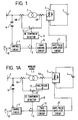
- Figure 1 is a schematic diagram of a control system for a power converter according to an embodiment of this invention.
- 5B is a current detector which detects the current on the primary winding side of transformer 2.
- 12 is a subtractor for finding the difference between the transformer secondary winding current detected by a current detector 5A and the transformer primary winding current detected by current detector 5B.
- Figure 2 shows a general equivalent circuit for transformer 2.
- X1 and X2 are leakage inductances of transformer 2; R1 and R2 are copper losses of transformer 2; X0 is an excitation inductance of transformer 2; and i1, i2 and i0 are respectively, a primary current, a secondary current and an excitation current flowing in transformer 2.
- the winding ratio of transformer 2 is taken as 1, excitation current i0 of transformer 2 is equal to the difference between primary current i1 and secondary current i2.
- Excitation current i0 almost corresponds to the magnetic flux of the core of transformer 2. Therefore, if a DC component included in excitation current i0 is detected, the value of DC magnetization can be estimated.
- the difference between the primary winding current and the secondary winding current of transformer 2 is computed by subtractor 12.
- a DC component in the current difference is detected by DC component detector 8.
- the output voltage instruction value from control circuit 7 is corrected by the DC component thus detected so that the DC magnetization is eliminated.
- the DC magnetization of transformer 2 can be suppressed.
- both DC magnetization due to the DC component included in the output of self-commutated converter 3 and the DC magnetization due to the transient DC component included in power system 1 can be corrected.
- Figure 1 shows the embodiment wherein the winding ratio of transformer 2 is taken as 1. This invention is not limited to this embodiment.
- Figure 1A shows a control system for a power converter according to another embodiment of this invention wherein the winding ratio of transformer 2 is 1 : n.
- 17 is a multiplier which multiplies the secondary winding current of transformer 2 detected by current detector 5A by n.
- the output of multiplier 17 is applied to subtractor 12, which finds the difference between the transformer primary current and the output of multiplier 17.
- the following control is executed the same as in the embodiment shown in Figure 1.
- the magnitude of the secondary winding current of transformer 2 is 1/n times that of the primary winding current of transformer 2.
- Multiplier 17 is provided for this purpose.
- a divider may be provided between current detector 5B and subtractor 12 which divides the primary winding current of transformer 2 detected by current detector 5B by n.
- FIG. 1B shows a control system for a power converter according to a further embodiment of this invention wherein power converter 3 is a three-phase power converter.
- transformer 2 is composed of a star-delta connection.
- 5A1, 5A2 and 5A3 are current detectors for detecting the currents on the secondary windings of transformer 2, respectively.
- 5B1, 5B2 and 5B3 are current detectors for detecting the currents on the primary windings of transformer 2, respectively.
- a star-delta conversion circuit 18 is provided for this purpose.
- the primary winding currents detected by current transformers 5B1, 5B2 and 5B3 are applied to star-delta conversion circuit 18.
- 121, 122 and 123 are subtractors for finding the differences between the three outputs of star-delta conversion circuit 18 and the secondary winding currents detected by current transformers 5A1, 5A2 and 5A3, respectively.
- DC component detector 8 detects the DC components contained in the outputs of subtractors 121, 122 and 123 and applies them to adders 91, 92 and 93, respectively.
- Adders 91, 92 and 93 add the three phase components of the output of control circuit 7 and the three outputs of DC component detector 8, respectively and apply the respective sums to PWM control circuit 10.
- a delta-star conversion circuit may be provided between current transformers 5A1, 5A2 and 5A3 in the secondary side and subtractors 121, 122 and 123.
- circuit elements such as multiplier 17 and star-delta conversion circuit 18, are well known to those skilled in the art. Accordingly, the detailed description of the circuit construction of these circuit elements may be omitted.
- both the DC magnetization due to the DC components included in the output of the power converter and the DC magnetization due to the transient DC component included in the outer system can be corrected by: finding the difference between the primary winding current and the secondary winding current of the transformer; detecting the DC component included in this difference; and correcting the output voltage instruction value of the power converter based on this DC component as one of the magnetic flux relating values of transformer 2.
- the case is considered in which a current including DC component is flowing from power system 1 to self-commutated converter 3.
- the DC component of the primary winding current detected by current detector 5B is equal to that of the secondary winding current detected by current detector 5A is Figure 1, and no DC magnetization of transformer 2 occurs. Accordingly, the output of DC component detector 8 is zero, so that no correction to the instruction value outputted from control circuit 7 is executed.
- 19 is a phase detection circuit, such as a phase locked loop circuit, which outputs a signal at every fundamental period of power system 1.
- This signal is applied to a maximum value detection circuit 13 and a minimum value detection circuit 14.
- the current difference between the transformer primary current and secondary current computed by subtractor 12 is also applied to maximum value detection circuit 13 and minimum value detection circuit 14.
- Maximum value detection circuit 13 and minimum value detection circuit 14 detect the maximum and the minimum values of the current difference at every fundamental period of power system 1, respectively.
- 15 is an arithmetic circuit which computes the center value of the current difference at every fundamental period of power system 1 from the maximum and minimum values. The center value is applied to adder 9.
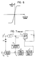
- FIG. 5 16 is a magnetic detector, such as a Hall element, for detecting the magnetic flux of the core of transformer 2.
- the output voltage instruction of control circuit 7 is corrected using the value of magnetic flux of the core of transformer 2, instead of the current difference between the transformer primary winding current and the transformer secondary winding current in Figure 3.
- the following control is executed the same as in the embodiment shown in Figure 3.
- the relationship between excitation current and magnetic flux in transformer 2 is non-linear.
- the excitation current only gradually increases until the core of transformer 2 reaches saturation. However, when the core reaches saturation, it increases rapidly. Therefore, in order to suppress DC magnetization by correcting before saturation is reached, the detection of a DC component of a small excitation current, or a small variation in excitation current. In order to detect such a small variation, the detection of the excitation current must be highly accurate.
- the magnitude of the excitation current is less than 10% of that of the rated current of a transformer. Therefore, when detecting the excitation current by the difference between the primary winding current and the secondary winding current, a current detector with an accuracy of 0.1% of the rated current is required in the case of detecting with an accuracy of 1% an excitation current the magnitude of which is 10% that of the rated current.
- both the DC magnetization due to the DC component included in the output of self-commutated converter 3 and the DC magnetization due to the transient DC component included in power system 1 can be effectively corrected.
- maximum value detection circuit 13 and minimum value detection circuit 14 detect the maximum and the minimum values from the inputted values at every fundamental period of power system 1. This invention is not limited to these embodiments. The maximum and the minimum values may be detected from the inputted values once for a plurality of fundamental periods of power system 1.
- a center value is computed in arithmetic circuit 15, and correction of the instruction value of control circuit 7 is executed by the center value.
- an appropriate value representing magnetic flux may be calculated from the magnetic flux or the exciting current in transformer 2 by a different method, and this value then may then be used for the correction of the instruction value from the control circuit, if DC magnetization of transformer 2 can be judged based on such a magnetic flux relating value.
- both the DC magnetization due to the DC component included in the power converter and the DC magnetization due to the transient DC component included in the outer system can be corrected by finding a value representing the magnetic flux of the core of the transformer,such as the difference between the DC primary winding current and the DC secondary winding current of the transformer, or a magnetic flux itself, and correcting the output voltage instruction value of the power converter based on the value representing magnetic flux.
Landscapes
- Engineering & Computer Science (AREA)
- Power Engineering (AREA)
- Physics & Mathematics (AREA)
- Electromagnetism (AREA)
- General Physics & Mathematics (AREA)
- Radar, Positioning & Navigation (AREA)
- Automation & Control Theory (AREA)
- Inverter Devices (AREA)
- Dc-Dc Converters (AREA)
- Supply And Distribution Of Alternating Current (AREA)
- Control Of Electrical Variables (AREA)
Abstract

Description
- This invention relates to a control system for a power converter, and more particularly relates to a control system for a power converter which is composed of self-turn-off devices such as, gate turn-off thyristors (hereafter, simply GTOs), and is connected to a power system or loads via transformers, which can prevent DC magnetization of the transformer.
- Figure 7 shows a schematic diagram of a prior art control system for a power converter which is composed of GTOs (hereafter, called a self-commutated converter), and is used in a DC transmission system or a static var compensator and so on.
- In Figure 7:
- 1 is a power system;
- 2 is a transformer for connecting a self-commutated
converter 3 composed of GTOs andpower system 1; - 4 is a DC power source such as capacitors etc.;
- 5 is a current detector which measures the output current of self-commutated
converter 3; - 6 is a potential transformer which measures the voltage of
power system 1; - 7 is a control circuit which controls the system voltage according to a
system voltage reference 51; - 8 is a DC component detector which detects the DC component contained in the output current of self-commutated
converter 3 measured bycurrent detector 5; - 9 is an adder which adds the output of control circuit 7 which is an instruction value for the output voltage of self-commutated
converter 3, and the output ofDC component detector 8; - 10 is a pulse-width modulation (PWM) control circuit which adjusts the output voltage of self-commutated
converter 3 by determining the firing timing of the GTOs in response to the output ofadder 9; and - 11 is a gate pulse amplifier circuit for generating gate pulses for GTOs in self-commutated
converter 3. - In Figure 7,
PWM control circuit 10 determines the GTO firing pattern so that no DC component is contained in the output voltage of self-commutatedconverter 3. However, the actual output voltage takes a waveform which contains a DC component due to the variations in the characteristic of the GTO and the variations in the gate signal transmission time. - When the output voltage of self-commutated
converter 3 contains a DC component, the core oftransformer 2 is magnetized asymmetrically because the voltage time product per cycle applied totransformer 2 does not become "0". Thus, the excitation current increases, and the output current of self-commutatedconverter 3 becomes over-current. This leads the stopping of operation of self-commutatedconverter 3 for its protection. In the worst case, this sometimes leads to damage to the devices forming the self-commutatedconverter 3. In the prior art circuit shown in Figure 7, to prevent DC magnetization the following control is performed. That is, the output current of self-commutatedconverter 3 is detected bycurrent detector 5 and the DC component generated in the course of DC magnetization is detected byDC component detector 8. PWM control is then executed by adding the detected DC component and the instruction value from control circuit 7. Therefore, the output voltage of self-commutatedconverter 3 is adjusted so that DC magnetization is eliminated. - The voltage of
power system 1 is usually AC voltage. However, transient DC components may be included in the voltage ofpower system 1 such as when connecting the power capacitor or the transformer topower system 1. In prior art technology, while it is possible to correct the DC component outputted from self-commutatedconverter 3, the DC magnetization due to the DC component generated bypower system 1 cannot be suppressed, because no correction due to the DC component of thepower system 1 side is made. Therefore, when a transient DC component is generated in thepower system 1,transformer 2 will be magnetized asymmetrically and lead to an over-current. - According to the present invention, there is provided a control system for a power converter having a plurality of switching devices and connected to an outer system through a transformer provided with a core, the control system comprising:
output voltage instruction value generating means for generating an instruction value for an output voltage of said power converter;
correction means for correcting said instruction value to generate a corrected instruction value for said output voltage of said power converter; and
signal generating means for generating a signal based on said corrected instruction value, said signal being applied to said switching devices of said power converter to control said output voltage of said power converter, characterised in that said correction means generates a corrected instruction value in dependence upon a value representing the magnetic flux of the core of the transformer. - The outer system may comprise a power supply or a load, and the system according to the invention enables suppression of DC magnetization of the transformer even for the DC component generated by the power system side (the outer system).
- A more complete appreciation of the invention and many of the attendant advantages thereof will be readily obtained as the same becomes better understood by reference to the following detailed description when considered in connection with the accompanying drawings, wherein:
- Figure 1 is a schematic block diagram showing a control system for a power converter according to an embodiment of this invention;
- Figure 1A is a schematic block diagram showing a control system for a power converter according to another embodiment of this invention;
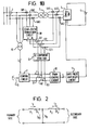
- Figure 1B is a schematic block diagram showing a control system for a power converter according to a further embodiment of this invention;
- Figure 2 is a simplified equivalent circuit of the
transformer 2 shown in Figure 1; - Figure 3 is a schematic block diagram showing a control system for a power converter according to another embodiment of this invention;
- Figure 4 is a diagram showing the relationship between magnetic flux and excitation current when an irregular AC voltage is applied;
- Figure 5 is a schematic block diagram showing a control system for a power converter according to a further embodiment of this invention;
- Figure 6 is a diagram showing the relationship between the excitation current and the magnetic flux in the transformer core; and
- Figure 7 is a schematic block diagram of showing a prior art control system for a power converter.
- Referring now to the drawings, wherein like reference numerals designate identical or corresponding parts throughout the several views, the embodiments of this invention will be described below.
- Figure 1 is a schematic diagram of a control system for a power converter according to an embodiment of this invention.
- In Figure 1, 5B is a current detector which detects the current on the primary winding side of
transformer 2. 12 is a subtractor for finding the difference between the transformer secondary winding current detected by acurrent detector 5A and the transformer primary winding current detected bycurrent detector 5B. - Figure 2 shows a general equivalent circuit for
transformer 2. In Figure 2, X1 and X2 are leakage inductances oftransformer 2; R1 and R2 are copper losses oftransformer 2; X0 is an excitation inductance oftransformer 2; and i1, i2 and i0 are respectively, a primary current, a secondary current and an excitation current flowing intransformer 2. As can be seen from the equivalent circuit in Figure 2, if, for simplicity, the winding ratio oftransformer 2 is taken as 1, excitation current i0 oftransformer 2 is equal to the difference between primary current i1 and secondary current i2. Excitation current i0 almost corresponds to the magnetic flux of the core oftransformer 2. Therefore, if a DC component included in excitation current i0 is detected, the value of DC magnetization can be estimated. Accordingly, in the embodiment shown in Figure 1, the difference between the primary winding current and the secondary winding current oftransformer 2 is computed bysubtractor 12. A DC component in the current difference is detected byDC component detector 8. Then the output voltage instruction value from control circuit 7 is corrected by the DC component thus detected so that the DC magnetization is eliminated. As a result, the DC magnetization oftransformer 2 can be suppressed. Also, since the correction is made by the excitation current, both DC magnetization due to the DC component included in the output of self-commutatedconverter 3 and the DC magnetization due to the transient DC component included inpower system 1 can be corrected. - The remainder of the circuit shown in Figure 1 functions in the same way as the circuit used in the prior art, shown in Figure 7, and explained hereinbefore.
- Figure 1 shows the embodiment wherein the winding ratio of
transformer 2 is taken as 1. This invention is not limited to this embodiment. Figure 1A shows a control system for a power converter according to another embodiment of this invention wherein the winding ratio oftransformer 2 is 1 : n. In Figure 1A, 17 is a multiplier which multiplies the secondary winding current oftransformer 2 detected bycurrent detector 5A by n. The output ofmultiplier 17 is applied tosubtractor 12, which finds the difference between the transformer primary current and the output ofmultiplier 17. The following control is executed the same as in the embodiment shown in Figure 1. - In case that the winding ratio of
transformer 2 is 1 : n, the magnitude of the secondary winding current oftransformer 2 is 1/n times that of the primary winding current oftransformer 2. In order to calculate the excitation current based on the primary and secondary winding currents oftransformer 2, it is necessary to multiply the secondary winding current by n.Multiplier 17 is provided for this purpose. - Instead of providing
multiplier 17 in Figure 1A, a divider may be provided betweencurrent detector 5B andsubtractor 12 which divides the primary winding current oftransformer 2 detected bycurrent detector 5B by n. - Figure 1B shows a control system for a power converter according to a further embodiment of this invention wherein
power converter 3 is a three-phase power converter. In this case,transformer 2 is composed of a star-delta connection. In Figure 1B, 5A1, 5A2 and 5A3 are current detectors for detecting the currents on the secondary windings oftransformer 2, respectively. 5B1, 5B2 and 5B3 are current detectors for detecting the currents on the primary windings oftransformer 2, respectively. As the type of the connection of the primary winding differs from that of the secondary winding intransformer 2, the phase of the primary winding current is different from that of the secondary winding current, so that it is necessary to convert the phase of the detected current. A star-delta conversion circuit 18 is provided for this purpose. The primary winding currents detected by current transformers 5B1, 5B2 and 5B3 are applied to star-delta conversion circuit 18. 121, 122 and 123 are subtractors for finding the differences between the three outputs of star-delta conversion circuit 18 and the secondary winding currents detected by current transformers 5A1, 5A2 and 5A3, respectively.DC component detector 8 detects the DC components contained in the outputs ofsubtractors adders Adders DC component detector 8, respectively and apply the respective sums toPWM control circuit 10. - Instead of providing star-
delta conversion circuit 18 in the primary side as shown in Figure 1B, a delta-star conversion circuit may be provided between current transformers 5A1, 5A2 and 5A3 in the secondary side andsubtractors - In these embodiments, circuit elements, such as
multiplier 17 and star-delta conversion circuit 18, are well known to those skilled in the art. Accordingly, the detailed description of the circuit construction of these circuit elements may be omitted. - As described above, according to these embodiments, in a power converter composed of self-turn-off devices and connected to an outer system, such as a power system or a load, via a transformer, both the DC magnetization due to the DC components included in the output of the power converter and the DC magnetization due to the transient DC component included in the outer system can be corrected by:
finding the difference between the primary winding current and the secondary winding current of the transformer;
detecting the DC component included in this difference; and
correcting the output voltage instruction value of the power converter based on this DC component as one of the magnetic flux relating values oftransformer 2. - Furthermore, the case is considered in which a current including DC component is flowing from
power system 1 to self-commutatedconverter 3. In this case, the DC component of the primary winding current detected bycurrent detector 5B is equal to that of the secondary winding current detected bycurrent detector 5A is Figure 1, and no DC magnetization oftransformer 2 occurs. Accordingly, the output ofDC component detector 8 is zero, so that no correction to the instruction value outputted from control circuit 7 is executed. - But in the prior art control system shown in Figure 7, only the secondary winding current of
transformer 2 is detected bycurrent transformer 5. As the DC component is included in the detected current, correction is erroneously made to the instruction value from control circuit 7 by the DC component fromDC component detector 8, even though the DC component of the excitation current is zero and DC magnetization oftransformer 2 does not occur. In such a case, this embodiment has the merit that an erroneous correction can be avoided. - The following is a description of another embodiment of this invention with reference to the schematic diagram in Figure 3.
- In Figure 3, 19 is a phase detection circuit, such as a phase locked loop circuit, which outputs a signal at every fundamental period of
power system 1. This signal is applied to a maximumvalue detection circuit 13 and a minimumvalue detection circuit 14. The current difference between the transformer primary current and secondary current computed bysubtractor 12 is also applied to maximumvalue detection circuit 13 and minimumvalue detection circuit 14. Maximumvalue detection circuit 13 and minimumvalue detection circuit 14 detect the maximum and the minimum values of the current difference at every fundamental period ofpower system 1, respectively. 15 is an arithmetic circuit which computes the center value of the current difference at every fundamental period ofpower system 1 from the maximum and minimum values. The center value is applied toadder 9. - When this embodiment is composed in this way, as shown in Figure 4 (a), even when a period occurs in which constant values continue for both magnetic flux and excitation current due to the application of an irregular AC voltage, the DC magnetization can be more accurately grasped by detecting the center value of the magnetic flux as that representing magnetic flux. Also, the effect of being able to correct both the DC magnetization due to the DC component included in the output of self-commutated
converter 3 and the DC magnetization due to the transient DC component included inpower system 1 can be obtained. - The following is a description of a further embodiment of this invention with reference to the schematic diagram in Figure 5. In Figure 5, 16 is a magnetic detector, such as a Hall element, for detecting the magnetic flux of the core of
transformer 2. - In Figure 5, the output voltage instruction of control circuit 7 is corrected using the value of magnetic flux of the core of
transformer 2, instead of the current difference between the transformer primary winding current and the transformer secondary winding current in Figure 3. The following control is executed the same as in the embodiment shown in Figure 3. As shown in Figure 6, the relationship between excitation current and magnetic flux intransformer 2 is non-linear. The excitation current only gradually increases until the core oftransformer 2 reaches saturation. However, when the core reaches saturation, it increases rapidly. Therefore, in order to suppress DC magnetization by correcting before saturation is reached, the detection of a DC component of a small excitation current, or a small variation in excitation current. In order to detect such a small variation, the detection of the excitation current must be highly accurate. However, usually, the magnitude of the excitation current is less than 10% of that of the rated current of a transformer. Therefore, when detecting the excitation current by the difference between the primary winding current and the secondary winding current, a current detector with an accuracy of 0.1% of the rated current is required in the case of detecting with an accuracy of 1% an excitation current the magnitude of which is 10% that of the rated current. - When correcting the output voltage instruction value by detecting the magnetic flux of the transformer core as shown in Figure 5, more effective control can be exercised than the case when the correction is carried out by detecting the excitation current.
- Also, when using this embodiment, both the DC magnetization due to the DC component included in the output of self-commutated
converter 3 and the DC magnetization due to the transient DC component included inpower system 1 can be effectively corrected. - In the embodiments shown in Figures 3 and 5, maximum
value detection circuit 13 and minimumvalue detection circuit 14 detect the maximum and the minimum values from the inputted values at every fundamental period ofpower system 1. This invention is not limited to these embodiments. The maximum and the minimum values may be detected from the inputted values once for a plurality of fundamental periods ofpower system 1. - Furthermore, a center value is computed in
arithmetic circuit 15, and correction of the instruction value of control circuit 7 is executed by the center value. Instead of the strict center value, an appropriate value representing magnetic flux may be calculated from the magnetic flux or the exciting current intransformer 2 by a different method, and this value then may then be used for the correction of the instruction value from the control circuit, if DC magnetization oftransformer 2 can be judged based on such a magnetic flux relating value. - In a power converter composed of self-turn-off devices which is connected to an outer system, such as a power system or a load, via a transformer, according to this invention, both the DC magnetization due to the DC component included in the power converter and the DC magnetization due to the transient DC component included in the outer system can be corrected by finding a value representing the magnetic flux of the core of the transformer,such as the difference between the DC primary winding current and the DC secondary winding current of the transformer,
or a magnetic flux itself, and correcting the output voltage instruction value of the power converter based on the value representing magnetic flux. - Obviously, numerous modifications and variations of the present invention are possible in light of the above teachings. It is therefore to be understood that within the scope of the appended claims, the invention may be practiced otherwise than as specifically described herein.
Claims (10)
- A control system for a power converter (3) having a plurality of switching devices and connected to an outer system (1) through a transformer (2) provided with a core, the control system comprising:
output voltage instruction value generating means (7) for generating an instruction value for an output voltage of said power converter (3);
correction means (5, 8, 9) for correcting said instruction value to generate a corrected instruction value for said output voltage of said power converter (3); and
signal generating means (10, 11) for generating a signal based on said corrected instruction value, said signal being applied to said switching devices of said power converter (3) to control said output voltage of said power converter (3), characterised in that said correction means (5A, 5B, 8, 9, 12; 5A, 5B, 9, 12, 13, 14, 15; 9, 13, 14, 15, 16) generates a corrected instruction value in dependence upon a value representing the magnetic flux of the core of the transformer (2). - The control system for a power converter according to claim 1, wherein said correction means includes:
magnetic flux detecting means (16) for detecting a magnetic flux of said core of said transformer (2);
maximum value detecting means (13) connected to receive said magnetic flux for detecting a maximum value of said magnetic flux during a perdetermined time:
minimum value detecting means (14) connected to receive said magnetic flux for detecting a minimum value of said magnetic flux during said predetermined time;
centre value calculating means (15) for calculating a centre value from said maximum value and said minimum value during said predetermined time, said centre value being said value representing magnetic flux; and
corrected instruction value generating means (9) connected to receive said instruction value and said magnetic flux relating value for generating said corrected instruction value for said output voltage of said power converter (3). - The control system for a power converter according to claim 2:
wherein said correction means further includes a phase detector (19) for detecting a fundamental period of said outer system (1); and
wherein in said correction means,
said magnetic flux detecting means (16) includes a Hall element provided in said transformer (2) for detecting said magnetic flux of said core of said transformer (2),
said maximum value detecting means (13) includes a maximum value detection circuit connected to receive said magnetic flux and said fundamental period as said predetermined time for detecting said maximum value of said magnetic flux during said fundamental period,
said minimum value detecting means (14) includes a minimum value detection circuit connected to receive said magnetic flux and said fundamental period as said predetermined time for detecting said minimum value of said magnetic flux during said fundamental period;
said centre value calculating means (15) includes an arithmetic circuit for calculating said centre value from said maximum value and said minimum value during said fundamental period, said centre value being said value representing magnetic flux; and
said correction instruction value generating means (9) includes an adder for adding said instruction value and said value representing magnetic flux to generate said corrected instruction value. - The control system for a power converter according to claim 1: wherein said correction means includes:
current different detecting means (5A, 5B, 12) for detecting a current difference between a primary winding current (i₁) and a secondary winding current (i₂) of said transformer (2);
maximum value detecting means (13) connected to receive said current difference for detecting a maximum value of said current difference during a predetermined time;
minimum value detecting means (14) connected to receive said current difference for detecting a minimum value of said current difference during said predetermined time;
centre value calculating means (15) for calculating a centre value from said maximum value and said minimum value during said predetermined time, said centre value being said value representing magnetic flux; and
corrected instruction value generating means (9) connected to receive said instruction value and said value representing magnetic flux for generating said corrected instruction value for said output voltage of said power converter. - The control system for a power converter according to claim 4:
wherein said correction means further includes a phase detector (19) for detecting a fundamental period of said outer system (1); and
wherein in said correction means,
said current difference detecting means includes,
a primary current detector (5B) for detecting said primary winding current of said transformer,
a secondary current detector (5A) for detecting said secondary winding current of said transformer, and
a subtractor (12) for computing said current difference between said primary winding current and said secondary winding current,
said maximum value detecting means (13) includes a maximum value detection circuit connected to receive said current difference and said fundamental period as said predetermined time for detecting said maximum value of said current difference during said fundamental period,
said minimum value detecting means (14) includes a minimum value detection circuit connected to receive said current difference and said fundamental period as said predetermined time for detecting said minimum value of said current difference during said fundamental period,
said centre value calculating means (15) includes an arithmetic circuit for calculating said centre value from said maximum value and said minimum value during said fundamental period, said centre value being said value representing magnetic flux, and
said corrected instruction value generating means includes an adder (9) for adding said instruction value and said value representing magnetic flux to generate said corrected instruction value. - The control system for a power converter according to claim 1, wherein said correction means includes:
current difference detecting means (5A, 5B) for detecting a current difference between a primary winding current and a secondary winding current of said transformer;
DC component detecting means (8) for detecting the DC component included in said current difference, said DC component being said value representing magnetic flux; and
corrected instruction value generating means (9) connected to receive said instruction value and said magnetic flux relating value for generating said corrected instruction value for said output voltage of said power converter. - The control system for a power converter according to claim 6, wherein said current difference detecting means includes:
a primary current detector (5B) for detecting said primary winding current of said transformer;
a secondary current detector (5A) for detecting said secondary winding current of said transformer; and
a subtractor (12) for computing said current difference between said primary winding current and said secondary winding current. - The control system for a power converter according to claim 6:
wherein the winding ratio of said transformer is 1 : n; and
wherein said current difference detecting means includes,
a primary current detector (5B) for detecting said primary winding current of said transformer,
a secondary current detector (5A) for detecting said secondary winding current of said transformer,
a multiplier (17) for multiplying said secondary winding current by n to generate a multiplied secondary winding current, and
a subtractor (12) for computing a difference between said primary winding current and said multiplied secondary winding current to output said difference as said current difference. - The control system for a power converter according to claim 6:
wherein said power converter (3) is a three-phase power converter, and said transformer (2) is composed of a star-delta connection; and
wherein said current difference detecting means includes,
primary current detecting means (5B1, 5B2, 5B3) for detecting said primary winding current of said transformer;
secondary current detecting means (5A1, 5A2, 5A3) for detecting said secondary winding current of said transformer;
star-delta conversion means (18) for converting said primary winding current into converted primary winding current; and
subtractor means (121, 122, 123) for computing a difference between said converted primary winding current and said secondary winding current, said difference being said current difference. - The control system for a power converter according to any preceding claim, wherein said outer system includes one of a power system and a load.
Applications Claiming Priority (2)
| Application Number | Priority Date | Filing Date | Title |
|---|---|---|---|
| JP5172766A JPH0728534A (en) | 1993-07-13 | 1993-07-13 | Power converter control device |
| JP172766/93 | 1993-07-13 |
Publications (2)
| Publication Number | Publication Date |
|---|---|
| EP0634833A1 true EP0634833A1 (en) | 1995-01-18 |
| EP0634833B1 EP0634833B1 (en) | 1998-10-28 |
Family
ID=15947946
Family Applications (1)
| Application Number | Title | Priority Date | Filing Date |
|---|---|---|---|
| EP94305108A Expired - Lifetime EP0634833B1 (en) | 1993-07-13 | 1994-07-13 | Control system for power converter |
Country Status (5)
| Country | Link |
|---|---|
| US (1) | US5450310A (en) |
| EP (1) | EP0634833B1 (en) |
| JP (1) | JPH0728534A (en) |
| CA (1) | CA2127834C (en) |
| DE (1) | DE69414197T2 (en) |
Cited By (1)
| Publication number | Priority date | Publication date | Assignee | Title |
|---|---|---|---|---|
| DE19734272C1 (en) * | 1997-08-07 | 1999-01-07 | Siemens Ag | Method and device for controlling distortions in the magnetizing current of a transformer, which is linked to a self-commutated converter with a power semiconductor switch that can be switched off |
Families Citing this family (10)
| Publication number | Priority date | Publication date | Assignee | Title |
|---|---|---|---|---|
| JP3167936B2 (en) * | 1996-08-08 | 2001-05-21 | 三菱電機株式会社 | Power converter |
| DE19648696A1 (en) * | 1996-11-25 | 1998-05-28 | Asea Brown Boveri | Method and device for regulating the DC offset of a converter |
| JP4449882B2 (en) * | 2005-10-14 | 2010-04-14 | 株式会社デンソー | Vehicle power generation control device |
| US8339818B2 (en) * | 2007-08-31 | 2012-12-25 | Abb Technology Ag | Method and device to compensate for an asymmetrical DC bias current in a power transformer connected to a high voltage converter |
| JP5646237B2 (en) * | 2010-07-26 | 2014-12-24 | 株式会社東芝 | Residual magnetic flux estimation method and residual magnetic flux estimation device for transformer |
| CN103262659B (en) * | 2010-12-15 | 2016-04-27 | 皇家飞利浦电子股份有限公司 | Power supply unit for X-ray tubes |
| DE102012218710B4 (en) | 2012-10-15 | 2016-08-04 | Continental Automotive Gmbh | Device for comparing the current through the main inductance of a transformer with a comparison value and two-position controller with such a device |
| JP2014150598A (en) * | 2013-01-31 | 2014-08-21 | Hitachi Ltd | Electric power conversion system and determination method for bias magnetism of transformer |
| JP6925503B2 (en) * | 2018-03-02 | 2021-08-25 | 三菱電機株式会社 | Power converter |
| JP6906464B2 (en) * | 2018-03-15 | 2021-07-21 | 株式会社東芝 | Power converter control device and control method |
Citations (3)
| Publication number | Priority date | Publication date | Assignee | Title |
|---|---|---|---|---|
| EP0361389A2 (en) * | 1988-09-26 | 1990-04-04 | Kabushiki Kaisha Toshiba | DC/AC power converting apparatus including DC component remover |
| DE4013171A1 (en) * | 1989-04-27 | 1990-10-31 | Mitsubishi Electric Corp | DEVICE FOR ELIMINATING DC VOLTAGE COMPONENTS FROM THE OUTPUT SIGNALS OF A MULTI-PHASE INVERTER |
| US5001619A (en) * | 1987-12-07 | 1991-03-19 | Kabushiki Kaisha Toshiba | Harmonics suppression control circuit for a PWM inverter |
Family Cites Families (10)
| Publication number | Priority date | Publication date | Assignee | Title |
|---|---|---|---|---|
| US3667027A (en) * | 1971-03-30 | 1972-05-30 | Bell Electronic Corp | Inverter circuit with stabilized frequency under all load conditions |
| US4173779A (en) * | 1978-12-08 | 1979-11-06 | Westinghouse Electric Corp. | Single-pole commutation circuit |
| US4611267A (en) * | 1985-02-25 | 1986-09-09 | General Electric Company | Snubber arrangements with energy recovery for power converters using self-extinguishing devices |
| JPH0724463B2 (en) * | 1986-03-07 | 1995-03-15 | 株式会社東芝 | Power converter |
| JPH02307374A (en) * | 1989-05-22 | 1990-12-20 | Hitachi Ltd | Power converter |
| JPH03139175A (en) * | 1989-10-24 | 1991-06-13 | Toshiba Corp | Pwm control power converter |
| JPH0728538B2 (en) * | 1990-04-18 | 1995-03-29 | 株式会社東芝 | PWM inverter control device |
| JP2774685B2 (en) * | 1990-09-12 | 1998-07-09 | 株式会社東芝 | Inverter control device with DC bias suppression control for three-phase transformer |
| JP3219783B2 (en) * | 1991-04-23 | 2001-10-15 | 株式会社東芝 | Power converter |
| JPH05236761A (en) * | 1992-02-20 | 1993-09-10 | Toshiba Corp | DC bias magnetism prevention device for transformer |
-
1993
- 1993-07-13 JP JP5172766A patent/JPH0728534A/en active Pending
-
1994
- 1994-07-12 CA CA002127834A patent/CA2127834C/en not_active Expired - Fee Related
- 1994-07-13 EP EP94305108A patent/EP0634833B1/en not_active Expired - Lifetime
- 1994-07-13 US US08/274,454 patent/US5450310A/en not_active Expired - Lifetime
- 1994-07-13 DE DE69414197T patent/DE69414197T2/en not_active Expired - Fee Related
Patent Citations (3)
| Publication number | Priority date | Publication date | Assignee | Title |
|---|---|---|---|---|
| US5001619A (en) * | 1987-12-07 | 1991-03-19 | Kabushiki Kaisha Toshiba | Harmonics suppression control circuit for a PWM inverter |
| EP0361389A2 (en) * | 1988-09-26 | 1990-04-04 | Kabushiki Kaisha Toshiba | DC/AC power converting apparatus including DC component remover |
| DE4013171A1 (en) * | 1989-04-27 | 1990-10-31 | Mitsubishi Electric Corp | DEVICE FOR ELIMINATING DC VOLTAGE COMPONENTS FROM THE OUTPUT SIGNALS OF A MULTI-PHASE INVERTER |
Cited By (2)
| Publication number | Priority date | Publication date | Assignee | Title |
|---|---|---|---|---|
| DE19734272C1 (en) * | 1997-08-07 | 1999-01-07 | Siemens Ag | Method and device for controlling distortions in the magnetizing current of a transformer, which is linked to a self-commutated converter with a power semiconductor switch that can be switched off |
| EP0896420A3 (en) * | 1997-08-07 | 2001-01-03 | Siemens Aktiengesellschaft | Method and device for suppressing magnetising current distortion in a transformer which is connected to a self-commutated power converter with semiconductor switches for power turn-off |
Also Published As
| Publication number | Publication date |
|---|---|
| US5450310A (en) | 1995-09-12 |
| JPH0728534A (en) | 1995-01-31 |
| CA2127834C (en) | 1997-06-03 |
| EP0634833B1 (en) | 1998-10-28 |
| CA2127834A1 (en) | 1995-01-14 |
| DE69414197T2 (en) | 1999-03-18 |
| DE69414197D1 (en) | 1998-12-03 |
Similar Documents
| Publication | Publication Date | Title |
|---|---|---|
| US5852554A (en) | Power inverter having three or more parallel driven PWM-type power inverting units | |
| EP0475709B1 (en) | Inverter control device capable of suppressing DC magnetization in three-phase transformer | |
| US5450310A (en) | Control system for power converter with prevention of DC magnetization in the transformer | |
| JP2010161843A (en) | Power conversion device | |
| US5621633A (en) | Apparatus for controlling converter having self-arc-extinction elements | |
| JP6443652B2 (en) | Power converter | |
| JP5955644B2 (en) | Inverter gate control circuit and inverter power supply device having the inverter gate control circuit | |
| JP3530748B2 (en) | Power converter | |
| JP3256814B2 (en) | Control device for polyphase power converter | |
| JP4607617B2 (en) | Control device for power converter | |
| JP3501548B2 (en) | Demagnetization prevention circuit of high frequency transformer | |
| JP2006136107A (en) | Semiconductor power conversion device and method for controlling bias | |
| JPH0728538B2 (en) | PWM inverter control device | |
| JPH11289775A (en) | Power converter | |
| JPH10229682A (en) | Power converter control method | |
| JP3302854B2 (en) | Induction motor control device | |
| JP2835165B2 (en) | Inverter control device with DC bias suppression control for three-phase transformer | |
| JP2509890B2 (en) | Pulse width modulation control method for AC / DC converter | |
| JP2025033404A (en) | Power Conversion Equipment | |
| JP2534035Y2 (en) | Inverter demagnetization prevention circuit for inverter | |
| JPH08266069A (en) | Power converter control device | |
| JPH06114569A (en) | Method and apparatus for controlling welding current of DC resistance welding apparatus | |
| JP3301165B2 (en) | Induction motor control device | |
| JP2001161079A (en) | Control device for power converter | |
| JPH0469716A (en) | Static reactive power compensator |
Legal Events
| Date | Code | Title | Description |
|---|---|---|---|
| PUAI | Public reference made under article 153(3) epc to a published international application that has entered the european phase |
Free format text: ORIGINAL CODE: 0009012 |
|
| 17P | Request for examination filed |
Effective date: 19940804 |
|
| AK | Designated contracting states |
Kind code of ref document: A1 Designated state(s): DE FR GB SE |
|
| 17Q | First examination report despatched |
Effective date: 19961204 |
|
| GRAG | Despatch of communication of intention to grant |
Free format text: ORIGINAL CODE: EPIDOS AGRA |
|
| GRAG | Despatch of communication of intention to grant |
Free format text: ORIGINAL CODE: EPIDOS AGRA |
|
| GRAH | Despatch of communication of intention to grant a patent |
Free format text: ORIGINAL CODE: EPIDOS IGRA |
|
| GRAH | Despatch of communication of intention to grant a patent |
Free format text: ORIGINAL CODE: EPIDOS IGRA |
|
| GRAA | (expected) grant |
Free format text: ORIGINAL CODE: 0009210 |
|
| AK | Designated contracting states |
Kind code of ref document: B1 Designated state(s): DE FR GB SE |
|
| PG25 | Lapsed in a contracting state [announced via postgrant information from national office to epo] |
Ref country code: FR Free format text: LAPSE BECAUSE OF FAILURE TO SUBMIT A TRANSLATION OF THE DESCRIPTION OR TO PAY THE FEE WITHIN THE PRESCRIBED TIME-LIMIT Effective date: 19981028 |
|
| REF | Corresponds to: |
Ref document number: 69414197 Country of ref document: DE Date of ref document: 19981203 |
|
| RIN2 | Information on inventor provided after grant (corrected) |
Free format text: KAWAKMI, NORIKO, C/O INTELLECTUAL PROPERTY DIV. |
|
| EN | Fr: translation not filed | ||
| RIN2 | Information on inventor provided after grant (corrected) |
Free format text: KAWAKAMI NORIKO, C/O INTELLECTUAL PROPERTY DIV. |
|
| PLBE | No opposition filed within time limit |
Free format text: ORIGINAL CODE: 0009261 |
|
| STAA | Information on the status of an ep patent application or granted ep patent |
Free format text: STATUS: NO OPPOSITION FILED WITHIN TIME LIMIT |
|
| 26N | No opposition filed | ||
| PGFP | Annual fee paid to national office [announced via postgrant information from national office to epo] |
Ref country code: GB Payment date: 20000713 Year of fee payment: 7 |
|
| PG25 | Lapsed in a contracting state [announced via postgrant information from national office to epo] |
Ref country code: GB Free format text: LAPSE BECAUSE OF NON-PAYMENT OF DUE FEES Effective date: 20010713 |
|
| GBPC | Gb: european patent ceased through non-payment of renewal fee |
Effective date: 20010713 |
|
| PGFP | Annual fee paid to national office [announced via postgrant information from national office to epo] |
Ref country code: DE Payment date: 20030724 Year of fee payment: 10 |
|
| PG25 | Lapsed in a contracting state [announced via postgrant information from national office to epo] |
Ref country code: DE Free format text: LAPSE BECAUSE OF NON-PAYMENT OF DUE FEES Effective date: 20050201 |
|
| PGFP | Annual fee paid to national office [announced via postgrant information from national office to epo] |
Ref country code: SE Payment date: 20130711 Year of fee payment: 20 |
|
| REG | Reference to a national code |
Ref country code: SE Ref legal event code: EUG |