EP0634816B1 - Shielded vertically aligned electrical connector components - Google Patents
Shielded vertically aligned electrical connector components Download PDFInfo
- Publication number
- EP0634816B1 EP0634816B1 EP94305157A EP94305157A EP0634816B1 EP 0634816 B1 EP0634816 B1 EP 0634816B1 EP 94305157 A EP94305157 A EP 94305157A EP 94305157 A EP94305157 A EP 94305157A EP 0634816 B1 EP0634816 B1 EP 0634816B1
- Authority
- EP
- European Patent Office
- Prior art keywords
- contacts
- housing
- shield
- electrical connector
- connector
- Prior art date
- Legal status (The legal status is an assumption and is not a legal conclusion. Google has not performed a legal analysis and makes no representation as to the accuracy of the status listed.)
- Expired - Lifetime
Links
Images


Classifications
-
- H—ELECTRICITY
- H01—ELECTRIC ELEMENTS
- H01R—ELECTRICALLY-CONDUCTIVE CONNECTIONS; STRUCTURAL ASSOCIATIONS OF A PLURALITY OF MUTUALLY-INSULATED ELECTRICAL CONNECTING ELEMENTS; COUPLING DEVICES; CURRENT COLLECTORS
- H01R13/00—Details of coupling devices of the kinds covered by groups H01R12/70 or H01R24/00 - H01R33/00
- H01R13/46—Bases; Cases
- H01R13/514—Bases; Cases composed as a modular blocks or assembly, i.e. composed of co-operating parts provided with contact members or holding contact members between them
-
- H—ELECTRICITY
- H01—ELECTRIC ELEMENTS
- H01R—ELECTRICALLY-CONDUCTIVE CONNECTIONS; STRUCTURAL ASSOCIATIONS OF A PLURALITY OF MUTUALLY-INSULATED ELECTRICAL CONNECTING ELEMENTS; COUPLING DEVICES; CURRENT COLLECTORS
- H01R13/00—Details of coupling devices of the kinds covered by groups H01R12/70 or H01R24/00 - H01R33/00
- H01R13/648—Protective earth or shield arrangements on coupling devices, e.g. anti-static shielding
- H01R13/658—High frequency shielding arrangements, e.g. against EMI [Electro-Magnetic Interference] or EMP [Electro-Magnetic Pulse]
- H01R13/6581—Shield structure
- H01R13/6585—Shielding material individually surrounding or interposed between mutually spaced contacts
-
- H—ELECTRICITY
- H01—ELECTRIC ELEMENTS
- H01R—ELECTRICALLY-CONDUCTIVE CONNECTIONS; STRUCTURAL ASSOCIATIONS OF A PLURALITY OF MUTUALLY-INSULATED ELECTRICAL CONNECTING ELEMENTS; COUPLING DEVICES; CURRENT COLLECTORS
- H01R13/00—Details of coupling devices of the kinds covered by groups H01R12/70 or H01R24/00 - H01R33/00
- H01R13/648—Protective earth or shield arrangements on coupling devices, e.g. anti-static shielding
- H01R13/658—High frequency shielding arrangements, e.g. against EMI [Electro-Magnetic Interference] or EMP [Electro-Magnetic Pulse]
- H01R13/6591—Specific features or arrangements of connection of shield to conductive members
- H01R13/65912—Specific features or arrangements of connection of shield to conductive members for shielded multiconductor cable
-
- H—ELECTRICITY
- H01—ELECTRIC ELEMENTS
- H01R—ELECTRICALLY-CONDUCTIVE CONNECTIONS; STRUCTURAL ASSOCIATIONS OF A PLURALITY OF MUTUALLY-INSULATED ELECTRICAL CONNECTING ELEMENTS; COUPLING DEVICES; CURRENT COLLECTORS
- H01R13/00—Details of coupling devices of the kinds covered by groups H01R12/70 or H01R24/00 - H01R33/00
- H01R13/66—Structural association with built-in electrical component
- H01R13/70—Structural association with built-in electrical component with built-in switch
- H01R13/703—Structural association with built-in electrical component with built-in switch operated by engagement or disengagement of coupling parts, e.g. dual-continuity coupling part
- H01R13/7031—Shorting, shunting or bussing of different terminals interrupted or effected on engagement of coupling part, e.g. for ESD protection, line continuity
- H01R13/7033—Shorting, shunting or bussing of different terminals interrupted or effected on engagement of coupling part, e.g. for ESD protection, line continuity making use of elastic extensions of the terminals
-
- H—ELECTRICITY
- H01—ELECTRIC ELEMENTS
- H01R—ELECTRICALLY-CONDUCTIVE CONNECTIONS; STRUCTURAL ASSOCIATIONS OF A PLURALITY OF MUTUALLY-INSULATED ELECTRICAL CONNECTING ELEMENTS; COUPLING DEVICES; CURRENT COLLECTORS
- H01R13/00—Details of coupling devices of the kinds covered by groups H01R12/70 or H01R24/00 - H01R33/00
- H01R13/646—Details of coupling devices of the kinds covered by groups H01R12/70 or H01R24/00 - H01R33/00 specially adapted for high-frequency, e.g. structures providing an impedance match or phase match
- H01R13/6461—Means for preventing cross-talk
- H01R13/6471—Means for preventing cross-talk by special arrangement of ground and signal conductors, e.g. GSGS [Ground-Signal-Ground-Signal]
-
- H—ELECTRICITY
- H01—ELECTRIC ELEMENTS
- H01R—ELECTRICALLY-CONDUCTIVE CONNECTIONS; STRUCTURAL ASSOCIATIONS OF A PLURALITY OF MUTUALLY-INSULATED ELECTRICAL CONNECTING ELEMENTS; COUPLING DEVICES; CURRENT COLLECTORS
- H01R13/00—Details of coupling devices of the kinds covered by groups H01R12/70 or H01R24/00 - H01R33/00
- H01R13/648—Protective earth or shield arrangements on coupling devices, e.g. anti-static shielding
- H01R13/658—High frequency shielding arrangements, e.g. against EMI [Electro-Magnetic Interference] or EMP [Electro-Magnetic Pulse]
- H01R13/6591—Specific features or arrangements of connection of shield to conductive members
- H01R13/6592—Specific features or arrangements of connection of shield to conductive members the conductive member being a shielded cable
-
- H—ELECTRICITY
- H01—ELECTRIC ELEMENTS
- H01R—ELECTRICALLY-CONDUCTIVE CONNECTIONS; STRUCTURAL ASSOCIATIONS OF A PLURALITY OF MUTUALLY-INSULATED ELECTRICAL CONNECTING ELEMENTS; COUPLING DEVICES; CURRENT COLLECTORS
- H01R2201/00—Connectors or connections adapted for particular applications
- H01R2201/04—Connectors or connections adapted for particular applications for network, e.g. LAN connectors
-
- H—ELECTRICITY
- H01—ELECTRIC ELEMENTS
- H01R—ELECTRICALLY-CONDUCTIVE CONNECTIONS; STRUCTURAL ASSOCIATIONS OF A PLURALITY OF MUTUALLY-INSULATED ELECTRICAL CONNECTING ELEMENTS; COUPLING DEVICES; CURRENT COLLECTORS
- H01R24/00—Two-part coupling devices, or either of their cooperating parts, characterised by their overall structure
- H01R24/60—Contacts spaced along planar side wall transverse to longitudinal axis of engagement
- H01R24/62—Sliding engagements with one side only, e.g. modular jack coupling devices
-
- H—ELECTRICITY
- H01—ELECTRIC ELEMENTS
- H01R—ELECTRICALLY-CONDUCTIVE CONNECTIONS; STRUCTURAL ASSOCIATIONS OF A PLURALITY OF MUTUALLY-INSULATED ELECTRICAL CONNECTING ELEMENTS; COUPLING DEVICES; CURRENT COLLECTORS
- H01R31/00—Coupling parts supported only by co-operation with counterpart
- H01R31/08—Short-circuiting members for bridging contacts in a counterpart
-
- H—ELECTRICITY
- H01—ELECTRIC ELEMENTS
- H01R—ELECTRICALLY-CONDUCTIVE CONNECTIONS; STRUCTURAL ASSOCIATIONS OF A PLURALITY OF MUTUALLY-INSULATED ELECTRICAL CONNECTING ELEMENTS; COUPLING DEVICES; CURRENT COLLECTORS
- H01R4/00—Electrically-conductive connections between two or more conductive members in direct contact, i.e. touching one another; Means for effecting or maintaining such contact; Electrically-conductive connections having two or more spaced connecting locations for conductors and using contact members penetrating insulation
- H01R4/24—Connections using contact members penetrating or cutting insulation or cable strands
- H01R4/2416—Connections using contact members penetrating or cutting insulation or cable strands the contact members having insulation-cutting edges, e.g. of tuning fork type
- H01R4/242—Connections using contact members penetrating or cutting insulation or cable strands the contact members having insulation-cutting edges, e.g. of tuning fork type the contact members being plates having a single slot
- H01R4/2425—Flat plates, e.g. multi-layered flat plates
- H01R4/2429—Flat plates, e.g. multi-layered flat plates mounted in an insulating base
Definitions
- the present invention relates to an improvement in electrical connector components. More particularly, the present invention relates to a shielded electrical connector for terminating a multiconductor cable having vertically aligned connector components.
- a closed-loop system provides for continuity of signal in a multicomponent system when certain of the components are not interconnected.
- these connectors are designed to carry signals at increasingly higher data rates. At such higher data rates, cross-talk interference between components of the connector also increases. Thus, these connectors must include adequate shielding so as to reduce cross-talk interference between connector components.
- an electrical connector comprising:
- the connector includes the upper row of contacts having a downwardly depending shunt member extending for engagement with portions of the lower contacts.
- the conductive shielding in the preferred embodiment extends between two of the contacts in each row and also between the downwardly depending shunt member.
- Figure 1 shows a shielded multiconductor electrical cable used in combination with the present invention.
- Figure 2 is a perspective showing of the electrical connector component assembly of the present invention.
- Figures 3 and 4 are rear-plan and side-elevational showings, respectively, of the electrical connector component assembly of Figure 2.
- Figures 5 and 6 are top and side fragmented showings, respectively, of an electrical contact used in the electrical connector component assembly shown in Figure 2.
- Figure 7 is an exploded perspective view of a further embodiment of the electrical connector component assembly of the present invention.
- Figure 8 is a perspective showing of the outer housing of the electrical connector component assembly of Figure 7.
- Figure 9 is an exploded perspective view of the outer housing of Figure 8.
- Figure 10 shows electrical connector component assembly of Figure 7 shown connected to a like connector in hermaphroditic fashion.
- Electrical cable 10 is a multiconductor data transmission cable including a plurality of insulated conductors 12 enclosed in an outer insulative jacket 14.
- a metallic shield 16 is interposed between the conductors 12 and the jacket 14.
- Shield 16 is used to provide electrical shielding for cable 10.
- a braided shield 16 is shown.
- shields of other construction, such as metallic foil may also be employed.
- Cable 10 is shown prepared for termination with end portions of conductors 12 extending outwardly of jacket 14. A portion of shield 16 is also shown extending from jacket 14.
- Assembly 20 includes first and second electrically insulative housings 22 and 24 arranged in a vertically stacked relationship. Each housing 22 and 24 supports a pair of electrical contacts 26 and 28 respectively. Assembly 20 further includes a pair of conductor support blocks 30 and 32 which are engagable with housings 22 and 24, respectively, to support conductors 12 of electrical cable 10 in electrical engagement with contacts 26 and 28, as will be further described hereinbelow.
- Electrical connector component assembly 20 may be housed within an electrically shielded housing (not shown) to permit electrical interconnection with a further connection device.
- Connector component assembly 20 and its associated shielded housing may be constructed to be of the hermaphroditic variety so that it will permit interconnection to an identically formed member. Connectors of such construction are shown in several of the above-identified U. S. patents, most notably, U. S. Patent No. 4,682,836.
- Housing 24 which is the lower of the two housings shown in the drawings, includes a bottom wall 34 and two transversely spaced upstanding sidewalls 36 and 38.
- An upstanding dividing wall 40 suitably electrically isolates contacts 28.
- a transverse wall 42 of height less than the sidewalls extends across a rear portion of bottom wall 34.
- Contacts 28 are supported by housing 24.
- Contacts 28 are formed of a suitably conductive stamped and formed metallic material such as beryllium copper.
- Contacts 28 include a generally elongate base portion 28a, an insulation displacement contact (IDC) portion 28b and a reversely bent cantilevered spring portion 28c, which extends back over base portion 28a.
- IDC portion 28b is of conventional flat-blade configuration, having two spaced relatively sharp tines 28d and 28e, defining therebetween a conductor receiving slot 28f.
- IDC portion 28b is shown extending in a direction opposite that of reversely bent cantilevered spring portion 28c so that it may be accessible adjacent bottom wall 34.
- a contact transition portion 28g provides for the inversion of IDC portion 28b.
- Contacts 28 are fixedly secured in housing 24 with contact base portion 28a positioned along bottom wall 34.
- Appropriate housing structure (not shown) inclusive of transverse wall 42 may be employed to support IDC portion 28b in housing 24.
- Cantilevered spring portion 28c is deflectable to move toward and away from base portion 28a upon interconnection of a further connecting device in a manner well-known in the art. Upon interconnection, cantilevered spring portion 28c will deflect downwardly toward base portion 28a, returning to its original position shown in Figure 4 upon disconnection.
- Housing 22 shown as the upper housing in the drawings, is of substantially similar construction to that of housing 24.
- Housing 22 includes a bottom wall 44 and two transversely spaced upstanding sidewalls 46 and 48.
- An upstanding dividing wall 50 electrically isolates contacts 26.
- a transverse wall 52 of height less than the sidewalls extends upwardly from a rear portion of bottom wall 44.
- Contacts 26 are of construction similar to that of contacts 28 described above.
- Contacts 26 include an elongate base portion 26a, an insulation displacing contact (IDC) portion 26b and a reversely bent cantilevered spring portion 26c.
- IDC portion 26b is also of generally flat blade configuration, having sharp tines 26d and 26e defining therebetween a conductor receiving slot 26f.
- IDC portion 26b extends upwardly from base 26a in the direction of cantilevered spring portion 26c, which is of opposite construction to that of contact 28.
- the IDC portions 26b, 28b of contacts 26 and 28 are accessible from opposite directions.
- each contact 26 further includes a depending shunt portion 26g.
- Shunt portion 26g is struck from a central extent of the planar base portion 26a and is bent downwardly out of the plane of base portion 26a to extend at an angle of approximately 90° with respect thereto.
- contacts 26 are fixedly secured in housing 22 with each contact 26 being supported on bottom wall 44.
- Transverse wall 52 is appropriately constructed to support IDC portions 26b of contacts 26.
- bottom wall 44 includes a pair of openings (not shown) which permit shunt portions 26g of contacts 26 to extend therethrough.
- each contact 26 extends downwardly toward contact 28, which is vertically aligned therewith, such that a distal extent 26h electrically engages cantilevered spring portion 28c. In this condition, contact 26 is electrically shunted to contact 28.
- cantilevered spring portion 28c of contact 28 is deflectable toward and away from base portion 28a.
- cantilevered spring portion 28c of contact 28 Upon interconnection of another connecting device, cantilevered spring portion 28c of contact 28 will deflect downwardly from the position shown in Figure 4 so that cantilevered spring portion 28c is out of engagement with depending shunt portion 26g of contact 26.
- cantilevered spring portion 28c Upon disconnection, cantilevered spring portion 28c will return to its original position, as shown in Figure 4, reconnecting with depending shunt portion 26g of contact 26.
- support blocks 30 and 32 are employed.
- Support blocks 30 and 32 are of substantially similar construction.
- block 30 is formed of suitably insulative molded plastic and includes a pair of spaced conductor receiving bores 60 and 62, which accommodate two conductors 12 of cable 10.
- a pair of IDC receiving slots 64 and 66 are positioned adjacent conductor receiving bores 60 and 62 and are in communication therewith.
- two of the conductors 12 are inserted into bores 60 and 62 of block 30.
- the block 30 is then inserted into housing 22 such that IDC portions 26b are accommodated in IDC receiving slots 64 and 66.
- Appropriate mating structure on sidewalls 46 and 48 and on conductor support block 30 facilitates insertion of support block 30 into housing 22.
- sidewalls 46 and 48 include vertical slots 46a and 48a which accommodate extending tongues 30a and 30b of block 30.
- other mating structure may also be employed.
- a latch or detent such as shown as 31 on block 30 may be employed to provide for a snap fit of block 30 in housing 22.
- Support block 30, including conductors 12 supported therein, may be manually inserted or inserted under application of an appropriate tool such that conductors 12 are electrically terminated with IDC portions 26b in a manner well-known in the connector art.
- Conductor support block 30 may be formed of a clear molded plastic so that the proper termination of conductors 12 to IDC portions 26b may be observed.
- Conductor support block 32 being substantially similar to that of conductor support block 30, operates in the same manner to terminate the other two conductors 12 of cable 10 to contacts 28 supported in housing 24.
- conductor support block 32 may be identical to conductor support block 30 so that a single construction may be used in both instances.
- connector component assembly 20 is supported within a shielded housing for interconnection purposes.
- the shield of that housing would be appropriately electrically connected to shield 16 of cable 10 which extends from jacket 14. Therefore, in order to maintain shielded isolation as between contacts 26 and 28, the present invention contemplates interposing a metallic shield between housing 22 and housing 24. This metallic shield would be electrically continuous with the shield of the outer housing, which is in turn connected to the shield 16 of cable 10.
- Electrical connector component assembly 120 includes first and second electrically insulative housings 122 and 124 arranged in vertically stacked relationship. Each housing 122 and 124 supports four electrical contacts 126 and 128, respectively. Assembly 120 further includes a pair of conductive support blocks 130 and 132 which are engagable with housings 122 and 124, respectively, to support conductors 12 of electrical cable 10 (Fig. 1) in electrical engagement with contacts 126 and 128 in a manner similar to that described hereinabove.
- Electrical connector component assembly 120 further includes an outer electrically shielded outer housing 131 formed of side by side matable housing members 125 and 129 which support the remainder of the components of connector component assembly 120.
- Housings 122 and 124 support contact shields 138 and 139, respectively.
- Housing 122 which is substantially similar to housing 124, includes a bottom wall 122a and transversely spaced upstanding side walls 122b and 122c.
- a central upstanding dividing wall 122d separates the contacts 126 supported therein into two side by side pairs.
- a central slot 122e extends through upstanding dividing wall 122d for accommodation of shield 138 as will be described in further detail hereinbelow.
- Contacts 126 are substantially similar to contacts 26 described above and include a depending shunt portion 126g extending from planar base portion 126a.
- Contacts 128 are substantially similar to contacts 28 described above and include a cantilevered spring portion 128c which is designed for engagement with shunt portion 126g in a manner shown and described with respect to Figures 5 and 6 above. While contacts 126 and 128 are shown as being stamped and formed metallic members with cantilevered portions 126c and 128c being reversely bent back over central base portions 126a and 128a, other contact configurations may also be employed.
- Each of housings 122 and 124 are constructed to accommodate shields 138 and 139, respectively therein.
- Shield 138 which is substantially similar to shield 139, is a metallic member formed of stamped material having a bottom planar surface 162, which is constructed to be in conformance with bottom wall 122a of housing 122, and a pair of upstanding transversely spaced side extensions 164 and 166.
- a planar central extension 168 extends upwardly from bottom planar surface 162 between side extensions 164 and 166.
- Side extensions 164 and 166 are constructed to be received along side walls 122b and 122c, respectively, and central extension 168 is designed to be received within central slot 122e of upstanding dividing wall 122d.
- Each of side extensions 164 and 166 and central extension 168 is of sufficient height and length to span the length of contacts 126 supported therein including depending shunt member 126g so as to provide cross-talk shielding for the contacts supported on either side of upstanding dividing wall 122a.
- contact shield 138 in combination with contact shield 139 of lower housing 124 assures that adequate cross-talk shielding is provided between contacts 126 and 128 supported within connector component assembly 120. While a stamped and formed shield is shown in Figure 7, it is contemplated that contact shields 138 and 139 may be integrally formed into a one-piece member formed of die cast metal.
- outer housing members 125 and 129 are shown being matable members forming overall outer housing 131.
- Outer housing members 125 and 129 have generally similar configurations.
- outer housing member 129 it includes three angularly disposed back walls. Central back wall 140 is flanked by lateral walls 142 and 144 which are disposed at generally 45° angles therefrom. Each of walls 140, 142 and 144 includes a semi-circular frangible housing portion 146. Frangible housing portion 146 may be manually removed creating a semi-circular aperture for passage of electrical cable 10 therethrough. As shown in Figure 8, when connector housing member 125 is secured to connector housing member 129, both semi-circular frangible members 146 and 148 form a full circular member which facilitates such cable passage. Thus, cable 10 may be inserted into outer connector housing 131 in either straight through fashion or at 45° angles therefrom.
- connector housing member 125 when assembled is designed for hermaphroditic mating in a manner shown in Figure 10.
- connector housing member 125 includes a deflectable connector latch 150 which comprises a cantilevered arm 152, a manually actuatable surface 154 and a locking member 156.
- Locking member 156 includes ramped engagement wall 158 and a locking wall 159 which extends downwardly from ramped engagement wall 158.
- Outer housing member 129 includes a latch retention member 160 which is supported on a wall 161 opposite wall 151 which supports latch 150.
- Latch retention member 160 includes a ramped wall 162 and a recess 164 beginning at the upper edge of ramped wall 162.
- outer connector housing 131 is designed for hermaphroditic interconnection with like connector 131'.
- latch 150 of outer connector housing 131 is designed for matable locking interconnection with latch engagement member 160' of outer connector housing 131'.
- ramped wall 158 of locking member 156 engages ramped wall 162 of latch engagement member 160'. This action causes the deflection of cantilevered arm 152, permitting such interaction.
- latch member 156 is forced into recess 164' by the spring bias of cantilevered arm 152 thus locking latch 150 to latch retention member 160'.
- a similar interaction occurs on the other side of outer connector housings 131 and 131' with respect to latch 150' and latch retention member 160 (not shown).
- manually actuatable surface 154 may be actuated by the installer to move against the bias of cantilevered arm 152 to release latch 150 from recess 164'. This will cause engagement of ramped walls 158 and 162' thereby disconnecting housing 131 from housing 131'. While manually actuatable surface 154 is shown to be a curved recessed member, it is also contemplated that a bump or protrusion with griping elements may be employed to facilitate easy manual engagement of the latch by the fingers of the installer.
Landscapes
- Details Of Connecting Devices For Male And Female Coupling (AREA)
- Connections By Means Of Piercing Elements, Nuts, Or Screws (AREA)
Description
- The present invention relates to an improvement in electrical connector components. More particularly, the present invention relates to a shielded electrical connector for terminating a multiconductor cable having vertically aligned connector components.
- In transmitting data signals, electrical connectors are commonly used to terminate signal carrying multiconductor electrical cables which interconnect the various components of the data system. Many data systems require the components to be supported in an electrically closed loop. A closed-loop system provides for continuity of signal in a multicomponent system when certain of the components are not interconnected.
- In order to achieve such a closed loop when the components are frequently connected and disconnected, the connectors connecting such components use automatic shunting mechanisms so that a closed-loop connection is maintained even when the connector is in a non-connected condition. The use of such shunting connectors in a closed-loop data system is shown in numerous patents including: Re. 32,760, 4,449,778, 4,501,459, 4,508,415, 4,582,376, 4,602,833, 4,619,494, 4,641,906, 4,653,825, 4,671,599, 4,682,836, 4,711,507, 4,711,511, 4,731,032, 4,744,769, 4,859,201, 4,883,433, 4,884,981, 4,891,022, 5,030,114, 5,030,121, 5,035,647, 5,052,940, 5,074,803, 5,088,934, 5,104,337, 5,112,243, 5,122,076 and 5,169,346.
- While the connectors shown in the above-identified patents provide adequately for the connection of components in a data system, the increasing use of smaller components in such systems requires the use of smaller connectors. However, despite the reduction in size, these connectors still must provide closed loop connections.
- Additionally, these connectors are designed to carry signals at increasingly higher data rates. At such higher data rates, cross-talk interference between components of the connector also increases. Thus, these connectors must include adequate shielding so as to reduce cross-talk interference between connector components.
- It is, therefore, desirable to provide a data connector of reduced size, which provides adequate shunting to maintain closed-loop connections and which provides adequate shielding.
- It is an object of the present invention to provide an improved electrical data connector.
- It is a further object of the present invention to provide data connector components of reduced size which provide for adequate shunting.
- It is a still further object of the present invention to provide a data connector having vertically aligned components.
- It is still another object of the present invention to provide improved shielding in a data connector having vertically aligned components so as to reduce cross-talk interference between contacts of the connector.
- In the efficient attainment of these and other objects, the present invention provides an electrical connector comprising:
- an insulative housing having a mating end for engagement with a mating electrical connection device and a termination end;
- plural electrical contacts supported within said housing, said contacts being arranged in vertically spaced horizontally extending upper and lower rows, each contact of one row being paired in vertically stacked relationship with a contact of said other row;
- shunting means for electrically shunting said contact of each said vertically stacked pair, said shunting means being disconnected upon interconnection of another electrical connection device with the connector;
- a conductive shield supported within said insulative housing, said shield including a shield portion extending between at least two of said contacts in said upper row between at least two of said contacts in said lower row and between said shunting means.
- As more particularly described by way of the preferred embodiment herein, the connector includes the upper row of contacts having a downwardly depending shunt member extending for engagement with portions of the lower contacts. The conductive shielding in the preferred embodiment extends between two of the contacts in each row and also between the downwardly depending shunt member.
- Figure 1 shows a shielded multiconductor electrical cable used in combination with the present invention.
- Figure 2 is a perspective showing of the electrical connector component assembly of the present invention.
- Figures 3 and 4 are rear-plan and side-elevational showings, respectively, of the electrical connector component assembly of Figure 2.
- Figures 5 and 6 are top and side fragmented showings, respectively, of an electrical contact used in the electrical connector component assembly shown in Figure 2.
- Figure 7 is an exploded perspective view of a further embodiment of the electrical connector component assembly of the present invention.
- Figure 8 is a perspective showing of the outer housing of the electrical connector component assembly of Figure 7.
- Figure 9 is an exploded perspective view of the outer housing of Figure 8.
- Figure 10 shows electrical connector component assembly of Figure 7 shown connected to a like connector in hermaphroditic fashion.
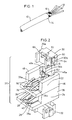
- Referring to Figure 1, an
electrical cable 10 of the type used in accordance with the present invention is shown.Electrical cable 10 is a multiconductor data transmission cable including a plurality ofinsulated conductors 12 enclosed in an outer insulative jacket 14. Ametallic shield 16 is interposed between theconductors 12 and the jacket 14.Shield 16, as is well-known in the art, is used to provide electrical shielding forcable 10. In the present illustrative embodiment, abraided shield 16 is shown. However, shields of other construction, such as metallic foil, may also be employed.Cable 10 is shown prepared for termination with end portions ofconductors 12 extending outwardly of jacket 14. A portion ofshield 16 is also shown extending from jacket 14. - Referring to Figures 2-4, the electrical
connector component assembly 20 of the present invention may be described.Assembly 20 includes first and second electricallyinsulative housings housing electrical contacts Assembly 20 further includes a pair ofconductor support blocks housings conductors 12 ofelectrical cable 10 in electrical engagement withcontacts - Electrical
connector component assembly 20 may be housed within an electrically shielded housing (not shown) to permit electrical interconnection with a further connection device.Connector component assembly 20 and its associated shielded housing may be constructed to be of the hermaphroditic variety so that it will permit interconnection to an identically formed member. Connectors of such construction are shown in several of the above-identified U. S. patents, most notably, U. S. Patent No. 4,682,836. -
Housing 24, which is the lower of the two housings shown in the drawings, includes abottom wall 34 and two transversely spacedupstanding sidewalls wall 40 suitably electrically isolatescontacts 28. As shown in Figure 3, atransverse wall 42 of height less than the sidewalls extends across a rear portion ofbottom wall 34. -
Electrical contacts 28 are supported byhousing 24.Contacts 28 are formed of a suitably conductive stamped and formed metallic material such as beryllium copper.Contacts 28 include a generallyelongate base portion 28a, an insulation displacement contact (IDC)portion 28b and a reversely bent cantileveredspring portion 28c, which extends back overbase portion 28a.IDC portion 28b is of conventional flat-blade configuration, having two spaced relativelysharp tines conductor receiving slot 28f.IDC portion 28b is shown extending in a direction opposite that of reversely bent cantileveredspring portion 28c so that it may be accessibleadjacent bottom wall 34. A contact transition portion 28g provides for the inversion ofIDC portion 28b.Contacts 28 are fixedly secured inhousing 24 withcontact base portion 28a positioned alongbottom wall 34. Appropriate housing structure (not shown) inclusive oftransverse wall 42 may be employed to supportIDC portion 28b inhousing 24. - Cantilevered
spring portion 28c is deflectable to move toward and away frombase portion 28a upon interconnection of a further connecting device in a manner well-known in the art. Upon interconnection, cantileveredspring portion 28c will deflect downwardly towardbase portion 28a, returning to its original position shown in Figure 4 upon disconnection. -
Housing 22, shown as the upper housing in the drawings, is of substantially similar construction to that ofhousing 24.Housing 22 includes abottom wall 44 and two transversely spacedupstanding sidewalls upstanding dividing wall 50 electrically isolatescontacts 26. Atransverse wall 52 of height less than the sidewalls extends upwardly from a rear portion ofbottom wall 44. -
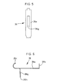
Contacts 26 are of construction similar to that ofcontacts 28 described above.Contacts 26 include anelongate base portion 26a, an insulation displacing contact (IDC)portion 26b and a reversely bent cantileveredspring portion 26c.IDC portion 26b is also of generally flat blade configuration, havingsharp tines conductor receiving slot 26f.IDC portion 26b extends upwardly frombase 26a in the direction ofcantilevered spring portion 26c, which is of opposite construction to that ofcontact 28. Thus, theIDC portions contacts - As shown in Figures 5 and 6, each
contact 26 further includes a dependingshunt portion 26g.Shunt portion 26g is struck from a central extent of theplanar base portion 26a and is bent downwardly out of the plane ofbase portion 26a to extend at an angle of approximately 90° with respect thereto. - Referring again to Figures 2-4,
contacts 26 are fixedly secured inhousing 22 with eachcontact 26 being supported onbottom wall 44.Transverse wall 52 is appropriately constructed to supportIDC portions 26b ofcontacts 26. Further,bottom wall 44 includes a pair of openings (not shown) which permitshunt portions 26g ofcontacts 26 to extend therethrough. - As shown particularly in Figure 4,
shunt portion 26g of eachcontact 26 extends downwardly towardcontact 28, which is vertically aligned therewith, such that adistal extent 26h electrically engages cantileveredspring portion 28c. In this condition, contact 26 is electrically shunted to contact 28. - As above described,
cantilevered spring portion 28c ofcontact 28 is deflectable toward and away frombase portion 28a. Upon interconnection of another connecting device, cantileveredspring portion 28c ofcontact 28 will deflect downwardly from the position shown in Figure 4 so that cantileveredspring portion 28c is out of engagement with dependingshunt portion 26g ofcontact 26. Upon disconnection, cantileveredspring portion 28c will return to its original position, as shown in Figure 4, reconnecting with dependingshunt portion 26g ofcontact 26. - To facilitate the termination of
cable 10 toconnector component assembly 20, conductor support blocks 30 and 32 are employed. Support blocks 30 and 32 are of substantially similar construction. Referring to supportblock 30 as an example, block 30 is formed of suitably insulative molded plastic and includes a pair of spaced conductor receiving bores 60 and 62, which accommodate twoconductors 12 ofcable 10. A pair ofIDC receiving slots cable 10, two of theconductors 12 are inserted intobores block 30. Theblock 30 is then inserted intohousing 22 such thatIDC portions 26b are accommodated inIDC receiving slots sidewalls conductor support block 30 facilitates insertion ofsupport block 30 intohousing 22. As shown in Figure 2, sidewalls 46 and 48 includevertical slots tongues 30a and 30b ofblock 30. However, other mating structure may also be employed. Also, a latch or detent such as shown as 31 onblock 30 may be employed to provide for a snap fit ofblock 30 inhousing 22.Support block 30, includingconductors 12 supported therein, may be manually inserted or inserted under application of an appropriate tool such thatconductors 12 are electrically terminated withIDC portions 26b in a manner well-known in the connector art.Conductor support block 30 may be formed of a clear molded plastic so that the proper termination ofconductors 12 toIDC portions 26b may be observed. -
Conductor support block 32, being substantially similar to that ofconductor support block 30, operates in the same manner to terminate the other twoconductors 12 ofcable 10 tocontacts 28 supported inhousing 24. In fact, it is contemplated thatconductor support block 32 may be identical toconductor support block 30 so that a single construction may be used in both instances. - As above-mentioned,
connector component assembly 20 is supported within a shielded housing for interconnection purposes. The shield of that housing would be appropriately electrically connected to shield 16 ofcable 10 which extends from jacket 14. Therefore, in order to maintain shielded isolation as betweencontacts housing 22 andhousing 24. This metallic shield would be electrically continuous with the shield of the outer housing, which is in turn connected to theshield 16 ofcable 10. - Referring to Figure 7, a preferred embodiment of the present invention is shown. For simplicity of explanation, like reference numerals are used to denote like components.
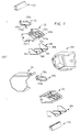
- Electrical
connector component assembly 120 includes first and second electricallyinsulative housings housing electrical contacts Assembly 120 further includes a pair of conductive support blocks 130 and 132 which are engagable withhousings conductors 12 of electrical cable 10 (Fig. 1) in electrical engagement withcontacts - Electrical
connector component assembly 120 further includes an outer electrically shieldedouter housing 131 formed of side by sidematable housing members connector component assembly 120. -
Housings support contact shields Housing 122, which is substantially similar tohousing 124, includes abottom wall 122a and transversely spacedupstanding side walls 122b and 122c. A centralupstanding dividing wall 122d separates thecontacts 126 supported therein into two side by side pairs. Acentral slot 122e extends throughupstanding dividing wall 122d for accommodation ofshield 138 as will be described in further detail hereinbelow. -
Contacts 126 are substantially similar tocontacts 26 described above and include a depending shunt portion 126g extending fromplanar base portion 126a.Contacts 128 are substantially similar tocontacts 28 described above and include acantilevered spring portion 128c which is designed for engagement with shunt portion 126g in a manner shown and described with respect to Figures 5 and 6 above. Whilecontacts cantilevered portions central base portions - One such particular configuration where the contacts are stamped such that the cantilevered spring portions are struck from the central base portion and bent out of the plane thereof are shown and described in our copending European application filed 13 July 1994 and claiming a priority date of 14 July 1993 from US Serial No. 08/092049 entitled Shielded Compact Data Connector.
- Each of
housings shields Shield 138, which is substantially similar to shield 139, is a metallic member formed of stamped material having a bottomplanar surface 162, which is constructed to be in conformance withbottom wall 122a ofhousing 122, and a pair of upstanding transversely spacedside extensions central extension 168 extends upwardly from bottomplanar surface 162 betweenside extensions Side extensions side walls 122b and 122c, respectively, andcentral extension 168 is designed to be received withincentral slot 122e ofupstanding dividing wall 122d. - Each of
side extensions central extension 168 is of sufficient height and length to span the length ofcontacts 126 supported therein including depending shunt member 126g so as to provide cross-talk shielding for the contacts supported on either side ofupstanding dividing wall 122a. Thus,contact shield 138 in combination withcontact shield 139 oflower housing 124 assures that adequate cross-talk shielding is provided betweencontacts connector component assembly 120. While a stamped and formed shield is shown in Figure 7, it is contemplated that contact shields 138 and 139 may be integrally formed into a one-piece member formed of die cast metal. - Referring additionally to Figures 8 an 9,
outer housing members outer housing 131.Outer housing members - Referring to
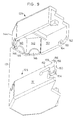
outer housing member 129, it includes three angularly disposed back walls. Centralback wall 140 is flanked bylateral walls walls frangible housing portion 146.Frangible housing portion 146 may be manually removed creating a semi-circular aperture for passage ofelectrical cable 10 therethrough. As shown in Figure 8, whenconnector housing member 125 is secured toconnector housing member 129, both semi-circularfrangible members 146 and 148 form a full circular member which facilitates such cable passage. Thus,cable 10 may be inserted intoouter connector housing 131 in either straight through fashion or at 45° angles therefrom. -
Outer connector housing 131 when assembled is designed for hermaphroditic mating in a manner shown in Figure 10. In that regard,connector housing member 125 includes adeflectable connector latch 150 which comprises acantilevered arm 152, a manuallyactuatable surface 154 and a lockingmember 156. Lockingmember 156 includes rampedengagement wall 158 and alocking wall 159 which extends downwardly from rampedengagement wall 158. -
Outer housing member 129 includes alatch retention member 160 which is supported on awall 161opposite wall 151 which supportslatch 150.Latch retention member 160 includes a rampedwall 162 and arecess 164 beginning at the upper edge of rampedwall 162. - As shown in Figure 10,
outer connector housing 131 is designed for hermaphroditic interconnection with like connector 131'. As can be seen, latch 150 ofouter connector housing 131 is designed for matable locking interconnection with latch engagement member 160' of outer connector housing 131'. Upon connectingouter housing 131 to outer housing 131', rampedwall 158 of lockingmember 156 engages rampedwall 162 of latch engagement member 160'. This action causes the deflection ofcantilevered arm 152, permitting such interaction. Upon reaching the end of respective ramp walls,latch member 156 is forced into recess 164' by the spring bias ofcantilevered arm 152 thus lockinglatch 150 to latch retention member 160'. A similar interaction occurs on the other side ofouter connector housings 131 and 131' with respect to latch 150' and latch retention member 160 (not shown). - In order to release
outer connector housing 131 from outer connector housing 131', manuallyactuatable surface 154 may be actuated by the installer to move against the bias ofcantilevered arm 152 to releaselatch 150 from recess 164'. This will cause engagement of rampedwalls 158 and 162' thereby disconnectinghousing 131 from housing 131'. While manuallyactuatable surface 154 is shown to be a curved recessed member, it is also contemplated that a bump or protrusion with griping elements may be employed to facilitate easy manual engagement of the latch by the fingers of the installer.
Claims (6)
- An electrical connector (120) comprising:an insulative housing (122,124) having a mating end for engagement with a mating electrical connection device and a termination end;plural electrical contacts (126,128) supported within said housing, said contacts being arranged in vertically spaced horizontally extending upper and lower rows, each contact (126) of one row being paired in vertically stacked relationship with a contact (128) of said other row;shunting means (126g) for electrically shunting said contact of each said vertically stacked pair, said shunting means being disconnected upon interconnection of another electrical connection device with the connector;a conductive shield (138,139) supported within said insulative housing (122,124), said shield including a shield portion (168) extending between at least two of said contacts (126) in said upper row between at least two of said contacts (128) in said lower row and between said shunting means (126g).
- An electrical connector of Claim 1 wherein said shunting means (126g) includes each of the contacts (126) of one of said upper rows including a depending shunt portion (126g), each said shunt portion (126g) for engagement with one of said contacts (128) of said lower row.
- An electrical connector of Claim 1 or Claim 2 wherein said conductive shield includes a pair of shield members (138,139).
- An electrical connector of Claim 3 wherein said conductive shield members (138,139) include lateral shield portions (164,166) extending on each side of each of said upper and lower rows.
- An electrical connector of Claim 4 wherein said conductive shield members (138,139) each include a shield portion (168) extending between at least two of said contacts of said upper and lower rows.
- An electrical connector of Claim 4 wherein said conductive shield portion (168) of at least one shield member (138) extends between said shunt portions (126g) of said at least two contacts.
Applications Claiming Priority (2)
| Application Number | Priority Date | Filing Date | Title |
|---|---|---|---|
| US92142 | 1993-07-14 | ||
| US08/092,142 US5531606A (en) | 1993-02-04 | 1993-07-14 | Shielded vertically aligned electrical connector components |
Publications (2)
| Publication Number | Publication Date |
|---|---|
| EP0634816A1 EP0634816A1 (en) | 1995-01-18 |
| EP0634816B1 true EP0634816B1 (en) | 1997-12-29 |
Family
ID=22231833
Family Applications (1)
| Application Number | Title | Priority Date | Filing Date |
|---|---|---|---|
| EP94305157A Expired - Lifetime EP0634816B1 (en) | 1993-07-14 | 1994-07-14 | Shielded vertically aligned electrical connector components |
Country Status (7)
| Country | Link |
|---|---|
| US (1) | US5531606A (en) |
| EP (1) | EP0634816B1 (en) |
| JP (1) | JP2927681B2 (en) |
| CA (1) | CA2127815A1 (en) |
| DE (1) | DE69407501T2 (en) |
| IL (1) | IL110327A (en) |
| SG (1) | SG52757A1 (en) |
Families Citing this family (12)
| Publication number | Priority date | Publication date | Assignee | Title |
|---|---|---|---|---|
| DE69820857T2 (en) * | 1997-10-30 | 2004-12-16 | Thomas & Betts International Inc., Sparks | CONNECTOR WITH IMPROVED SHIELDING AND MULTIPURPOSE TENSION RELIEF |
| US6077122A (en) | 1997-10-30 | 2000-06-20 | Thomas & Bett International, Inc. | Electrical connector having an improved connector shield and a multi-purpose strain relief |
| US6328601B1 (en) * | 1998-01-15 | 2001-12-11 | The Siemon Company | Enhanced performance telecommunications connector |
| US6325672B1 (en) | 1999-10-16 | 2001-12-04 | Berg Technology, Inc. | Electrical connector with internal shield and filter |
| US6390851B1 (en) | 1999-10-16 | 2002-05-21 | Berg Technology, Inc. | Electrical connector with internal shield |
| JP3638840B2 (en) * | 1999-12-02 | 2005-04-13 | 矢崎総業株式会社 | Connector connection method |
| US6431914B1 (en) * | 2001-06-04 | 2002-08-13 | Hon Hai Precision Ind. Co., Ltd. | Grounding scheme for a high speed backplane connector system |
| DE10334655A1 (en) * | 2003-07-22 | 2005-03-03 | ITT Manufacturing Enterprises, Inc. (n.d.Ges.d. Staates Delaware), Wilmington | Connector device for small servo motors |
| CN2800594Y (en) * | 2005-05-10 | 2006-07-26 | 富士康(昆山)电脑接插件有限公司 | Power supply connector |
| CN201112707Y (en) * | 2007-08-10 | 2008-09-10 | 富士康(昆山)电脑接插件有限公司 | electrical connector |
| DE102011055509B4 (en) * | 2011-11-18 | 2017-09-07 | Phoenix Contact Gmbh & Co. Kg | Connectors |
| WO2015164538A1 (en) | 2014-04-23 | 2015-10-29 | Tyco Electronics Corporation | Electrical connector with shield cap and shielded terminals |
Family Cites Families (22)
| Publication number | Priority date | Publication date | Assignee | Title |
|---|---|---|---|---|
| US3654592A (en) * | 1970-09-21 | 1972-04-04 | Berg Electronics Inc | Electrical connector and block |
| US4106841A (en) * | 1977-03-11 | 1978-08-15 | Bunker Ramo Corporation | Electrical connector for printed circuit boards |
| IE55318B1 (en) * | 1982-12-22 | 1990-08-01 | Amp Inc | Shunt-protected electrical connector |
| US4516825A (en) * | 1983-07-11 | 1985-05-14 | Stewart Stamping Corporation | Modular connector for terminating EMI/RFI shielded cordage |
| US4582376A (en) * | 1984-04-09 | 1986-04-15 | Amp Incorporated | Shorting bar having wiping action |
| US4659163A (en) * | 1984-06-13 | 1987-04-21 | Amp Incorporated | Filtered shielded connector assembly |
| JPH0436065Y2 (en) * | 1984-12-30 | 1992-08-26 | ||
| DE8531990U1 (en) * | 1985-11-13 | 1986-01-16 | C.A. Weidmüller GmbH & Co, 4930 Detmold | Electrical double connector with short-circuit bridge |
| US4756695A (en) * | 1986-06-13 | 1988-07-12 | Amp Incorporated | Local area network interface |
| US4838811A (en) * | 1986-08-22 | 1989-06-13 | Hirose Electric Co., Ltd. | Modular connector with EMI countermeasure |
| JPH02501870A (en) * | 1986-10-03 | 1990-06-21 | ミネソタ マイニング アンド マニユフアクチユアリング カンパニー | Shielded and grounded connector system for coaxial cables |
| US4824383A (en) * | 1986-11-18 | 1989-04-25 | E. I. Du Pont De Nemours And Company | Terminator and corresponding receptacle for multiple electrical conductors |
| JPH0250983U (en) * | 1988-10-04 | 1990-04-10 | ||
| US4939624A (en) * | 1988-12-14 | 1990-07-03 | Cray Research, Inc. | Interconnected multiple circuit module |
| JPH0733983Y2 (en) * | 1989-02-06 | 1995-08-02 | 豊田合成株式会社 | Mudguard |
| DE4032800A1 (en) * | 1990-10-16 | 1992-04-23 | Metz Albert Blumberger Tel | Plug for a plug and socket arrangement - has additional contacts to give wide range of electrical connections |
| US5178554A (en) * | 1990-10-26 | 1993-01-12 | The Siemon Company | Modular jack patching device |
| US5052948A (en) * | 1990-11-19 | 1991-10-01 | Itt Corporation | Connector ground and shield |
| US5088934A (en) * | 1991-02-20 | 1992-02-18 | Chian Chyun Enterprise Co. Ltd. | Electrical terminal |
| US5160273A (en) * | 1991-06-24 | 1992-11-03 | Porta Systems Corp. | Connector block assembly |
| JPH0521110A (en) * | 1991-07-10 | 1993-01-29 | Amp Japan Ltd | Shielding type electric connector |
| JP3091681U (en) * | 2002-07-26 | 2003-02-07 | 船井電機株式会社 | Electronic device having coaxial terminal and DVD playback device |
-
1993
- 1993-07-14 US US08/092,142 patent/US5531606A/en not_active Expired - Lifetime
-
1994
- 1994-07-12 CA CA002127815A patent/CA2127815A1/en not_active Abandoned
- 1994-07-14 IL IL11032794A patent/IL110327A/en not_active IP Right Cessation
- 1994-07-14 DE DE69407501T patent/DE69407501T2/en not_active Expired - Lifetime
- 1994-07-14 JP JP6162525A patent/JP2927681B2/en not_active Expired - Lifetime
- 1994-07-14 SG SG1996009045A patent/SG52757A1/en unknown
- 1994-07-14 EP EP94305157A patent/EP0634816B1/en not_active Expired - Lifetime
Also Published As
| Publication number | Publication date |
|---|---|
| DE69407501D1 (en) | 1998-02-05 |
| IL110327A0 (en) | 1994-10-21 |
| EP0634816A1 (en) | 1995-01-18 |
| IL110327A (en) | 1999-04-11 |
| JPH07192816A (en) | 1995-07-28 |
| SG52757A1 (en) | 1998-09-28 |
| US5531606A (en) | 1996-07-02 |
| JP2927681B2 (en) | 1999-07-28 |
| CA2127815A1 (en) | 1995-01-15 |
| DE69407501T2 (en) | 1998-04-16 |
Similar Documents
| Publication | Publication Date | Title |
|---|---|---|
| EP0570181B1 (en) | High frequency electrical connector | |
| EP0735612B1 (en) | Electrical connector having an improved conductor holding block and conductor shield | |
| EP0653811B1 (en) | Electrical connector strain relief | |
| US5586911A (en) | Shielding data connector | |
| EP0398560B1 (en) | Insulation displacement connector | |
| EP0653815B1 (en) | Electrical connector with cable shield ground clip | |
| JPH11508723A (en) | Patch cord assembly | |
| JPH07201379A (en) | Patch connector | |
| WO2002061883A2 (en) | High-density plug connector for twisted pair cable | |
| EP0634816B1 (en) | Shielded vertically aligned electrical connector components | |
| US5564940A (en) | Electrical connector having a conductor holding block | |
| US5681180A (en) | Conductor holding block for an electrical connector | |
| EP0610087B1 (en) | Vertically aligned electrical connector components | |
| EP0956619B1 (en) | Electrical connector having an improved connector shield and a multi-purpose strain relief | |
| EP0865113B1 (en) | Shielded data connector | |
| EP0653804B1 (en) | Electrical connector having a conductor holding block | |
| JPS61163574A (en) | Electric connector |
Legal Events
| Date | Code | Title | Description |
|---|---|---|---|
| PUAI | Public reference made under article 153(3) epc to a published international application that has entered the european phase |
Free format text: ORIGINAL CODE: 0009012 |
|
| AK | Designated contracting states |
Kind code of ref document: A1 Designated state(s): BE CH DE ES FR GB IT LI LU NL SE |
|
| 17P | Request for examination filed |
Effective date: 19950626 |
|
| 17Q | First examination report despatched |
Effective date: 19960325 |
|
| GRAG | Despatch of communication of intention to grant |
Free format text: ORIGINAL CODE: EPIDOS AGRA |
|
| GRAG | Despatch of communication of intention to grant |
Free format text: ORIGINAL CODE: EPIDOS AGRA |
|
| GRAH | Despatch of communication of intention to grant a patent |
Free format text: ORIGINAL CODE: EPIDOS IGRA |
|
| GRAH | Despatch of communication of intention to grant a patent |
Free format text: ORIGINAL CODE: EPIDOS IGRA |
|
| RAP1 | Party data changed (applicant data changed or rights of an application transferred) |
Owner name: THOMAS & BETTS CORPORATION (A TENNESSEE CORPORATIO |
|
| GRAA | (expected) grant |
Free format text: ORIGINAL CODE: 0009210 |
|
| AK | Designated contracting states |
Kind code of ref document: B1 Designated state(s): BE CH DE ES FR GB IT LI LU NL SE |
|
| PG25 | Lapsed in a contracting state [announced via postgrant information from national office to epo] |
Ref country code: LI Free format text: LAPSE BECAUSE OF FAILURE TO SUBMIT A TRANSLATION OF THE DESCRIPTION OR TO PAY THE FEE WITHIN THE PRESCRIBED TIME-LIMIT Effective date: 19971229 Ref country code: ES Free format text: THE PATENT HAS BEEN ANNULLED BY A DECISION OF A NATIONAL AUTHORITY Effective date: 19971229 Ref country code: CH Free format text: LAPSE BECAUSE OF FAILURE TO SUBMIT A TRANSLATION OF THE DESCRIPTION OR TO PAY THE FEE WITHIN THE PRESCRIBED TIME-LIMIT Effective date: 19971229 Ref country code: BE Free format text: LAPSE BECAUSE OF FAILURE TO SUBMIT A TRANSLATION OF THE DESCRIPTION OR TO PAY THE FEE WITHIN THE PRESCRIBED TIME-LIMIT Effective date: 19971229 |
|
| REG | Reference to a national code |
Ref country code: CH Ref legal event code: EP |
|
| REF | Corresponds to: |
Ref document number: 69407501 Country of ref document: DE Date of ref document: 19980205 |
|
| ET | Fr: translation filed | ||
| ITF | It: translation for a ep patent filed | ||
| PG25 | Lapsed in a contracting state [announced via postgrant information from national office to epo] |
Ref country code: SE Free format text: LAPSE BECAUSE OF FAILURE TO SUBMIT A TRANSLATION OF THE DESCRIPTION OR TO PAY THE FEE WITHIN THE PRESCRIBED TIME-LIMIT Effective date: 19980329 |
|
| REG | Reference to a national code |
Ref country code: CH Ref legal event code: PL |
|
| PLBE | No opposition filed within time limit |
Free format text: ORIGINAL CODE: 0009261 |
|
| STAA | Information on the status of an ep patent application or granted ep patent |
Free format text: STATUS: NO OPPOSITION FILED WITHIN TIME LIMIT |
|
| 26N | No opposition filed | ||
| REG | Reference to a national code |
Ref country code: FR Ref legal event code: TP Ref country code: FR Ref legal event code: CA |
|
| REG | Reference to a national code |
Ref country code: GB Ref legal event code: IF02 |
|
| PGFP | Annual fee paid to national office [announced via postgrant information from national office to epo] |
Ref country code: LU Payment date: 20130730 Year of fee payment: 20 |
|
| PGFP | Annual fee paid to national office [announced via postgrant information from national office to epo] |
Ref country code: DE Payment date: 20130729 Year of fee payment: 20 Ref country code: NL Payment date: 20130726 Year of fee payment: 20 |
|
| PGFP | Annual fee paid to national office [announced via postgrant information from national office to epo] |
Ref country code: FR Payment date: 20130717 Year of fee payment: 20 Ref country code: GB Payment date: 20130729 Year of fee payment: 20 |
|
| PGFP | Annual fee paid to national office [announced via postgrant information from national office to epo] |
Ref country code: IT Payment date: 20130724 Year of fee payment: 20 |
|
| REG | Reference to a national code |
Ref country code: DE Ref legal event code: R071 Ref document number: 69407501 Country of ref document: DE |
|
| REG | Reference to a national code |
Ref country code: NL Ref legal event code: V4 Effective date: 20140714 |
|
| REG | Reference to a national code |
Ref country code: GB Ref legal event code: PE20 Expiry date: 20140713 |
|
| PG25 | Lapsed in a contracting state [announced via postgrant information from national office to epo] |
Ref country code: DE Free format text: LAPSE BECAUSE OF EXPIRATION OF PROTECTION Effective date: 20140715 |
|
| PG25 | Lapsed in a contracting state [announced via postgrant information from national office to epo] |
Ref country code: GB Free format text: LAPSE BECAUSE OF EXPIRATION OF PROTECTION Effective date: 20140713 |