EP0634235A1 - Straightening machine for rolled profiles, especially H-profiles - Google Patents
Straightening machine for rolled profiles, especially H-profiles Download PDFInfo
- Publication number
- EP0634235A1 EP0634235A1 EP94110510A EP94110510A EP0634235A1 EP 0634235 A1 EP0634235 A1 EP 0634235A1 EP 94110510 A EP94110510 A EP 94110510A EP 94110510 A EP94110510 A EP 94110510A EP 0634235 A1 EP0634235 A1 EP 0634235A1
- Authority
- EP
- European Patent Office
- Prior art keywords
- straightening
- machine according
- worm
- straightening machine
- disks
- Prior art date
- Legal status (The legal status is an assumption and is not a legal conclusion. Google has not performed a legal analysis and makes no representation as to the accuracy of the status listed.)
- Granted
Links
- 238000006073 displacement reaction Methods 0.000 claims abstract description 6
- 210000003746 feather Anatomy 0.000 claims description 7
- 230000008859 change Effects 0.000 abstract description 3
- 238000005096 rolling process Methods 0.000 description 4
- 238000000034 method Methods 0.000 description 2
- 125000006850 spacer group Chemical group 0.000 description 2
- 230000007704 transition Effects 0.000 description 2
- 229910000831 Steel Inorganic materials 0.000 description 1
- 230000006978 adaptation Effects 0.000 description 1
- 230000005540 biological transmission Effects 0.000 description 1
- 238000006243 chemical reaction Methods 0.000 description 1
- 238000010276 construction Methods 0.000 description 1
- 230000001419 dependent effect Effects 0.000 description 1
- 235000021189 garnishes Nutrition 0.000 description 1
- 238000005098 hot rolling Methods 0.000 description 1
- 230000008569 process Effects 0.000 description 1
- 230000009467 reduction Effects 0.000 description 1
- 239000010959 steel Substances 0.000 description 1
Images


Classifications
-
- B—PERFORMING OPERATIONS; TRANSPORTING
- B21—MECHANICAL METAL-WORKING WITHOUT ESSENTIALLY REMOVING MATERIAL; PUNCHING METAL
- B21D—WORKING OR PROCESSING OF SHEET METAL OR METAL TUBES, RODS OR PROFILES WITHOUT ESSENTIALLY REMOVING MATERIAL; PUNCHING METAL
- B21D3/00—Straightening or restoring form of metal rods, metal tubes, metal profiles, or specific articles made therefrom, whether or not in combination with sheet metal parts
- B21D3/02—Straightening or restoring form of metal rods, metal tubes, metal profiles, or specific articles made therefrom, whether or not in combination with sheet metal parts by rollers
- B21D3/05—Straightening or restoring form of metal rods, metal tubes, metal profiles, or specific articles made therefrom, whether or not in combination with sheet metal parts by rollers arranged on axes rectangular to the path of the work
Definitions
- the invention relates to a straightening machine for rolled beams, in particular hyper-beams, hereinafter referred to as H-beam, in which at least one of the two straightening disks which bear against the carrier flanges from the inside and are supported by a straightening shaft is axially adjustable.
- a straightening shaft for straightening machines of this type has become known from DE-35 22 976 A1.
- This straightening machine is used to straighten rails.
- the flange thicknesses can vary.
- the determination of the height H enables optimized connections (gusset plates) of the girders with different resistance moments in steel buildings. So that H-beams can be rolled with different flange thicknesses, it is known to adjust the rolling disks of the roll in the rolling stands in carrier streets so that on the one hand the constant height dimension of the beam is maintained, and on the other hand different flange thicknesses can still be rolled.
- the adjustment time on the roll stand is about 30 seconds.
- the current straightening practice in a straightening machine downstream of the carrier line provides that the beams are moved into the straightening machine lying on the flanges and then run over the straightening disks with the web.
- the straightening disks are therefore fixed to a flange or mounting bushing via a spacer bushing or spacer washers, corresponding to the dimensions of the chamber, and completely replaced if necessary.
- This assembly bushing unit is placed directly on the straightening shaft and axially clamped there by means of a clamping nut or a clamping head. In the case of a changed chamber dimension due to different flange thicknesses, this is equivalent to a very time-consuming changeover time, since each chamber dimension deviation inevitably leads to a change in the assembly bushing unit.
- the invention has for its object to provide a straightening machine of the type mentioned, which allows the outer or chamber dimensions of the straightening disks to be changed quickly.
- a worm wheel drive is used for shifting the directional disk.
- the worm driving the worm wheel can be rotated manually, alternatively acted upon by a motor or rotated by means of an electric or pneumatic screwdriver.
- Very large adjustment ranges can be achieved by means of the worm wheel drive, where only differently dimensioned worm wheels need to be installed; the worm wheel drive for shifting the directional disc can be easily Retrofit in existing straightening machines, since only the mounting bush clamped with the straightening pin of the straightening shaft has to be changed. It is not necessary to change the existing directional shaft connection and, furthermore, no bearings in the axial direction are required.
- the straightening disk (s) be (are) firmly connected to an annular sleeve or displacement sleeve acted upon by the worm wheel drive.
- the worm wheel set in rotation thus acts directly translationally on the straightening disk or straightening disks to be adjusted, which are adjusted to a larger or smaller distance from one another in accordance with the changed flange thickness dimension of the carrier.
- a preferred embodiment provides that the worm wheel is mounted between the straightening disks on an assembly bushing enclosing the straightening pin of the straightening shaft and has wheel hubs on both sides which have external threads meshing with a corresponding internal thread of the ring sleeves. Due to the wheel hubs, there is a wheel widening with a smaller diameter than the worm wheel, and due to the intermeshing ring sleeve and wheel hub threads designed as a trapezoidal thread, the ring sleeves on the trapezoidal thread of the wheel hubs shift inwards or outwards, which is advantageously via a screw connection the associated ring sleeves attached alignment discs are taken; when moving, the two straightening discs cover the same adjustment paths.
- the worm housing is connected to an annular sleeve via a torque support so that torques arising during the transition from the rotor to the translatory movement can be absorbed harmlessly. It is sufficient here to provide only one of the two ring sleeves with a torque support.
- worm wheel drive provides that the worm wheel is arranged at a distance in front of the outer, facing the free end of the straightening shaft in the socket body of a clamping head and meshes on the one hand with the worm shaft mounted in the socket body and on the other hand via an internal thread with an external thread of the sliding bush .
- the worm wheel is arranged at a distance in front of the outer, facing the free end of the straightening shaft in the socket body of a clamping head and meshes on the one hand with the worm shaft mounted in the socket body and on the other hand via an internal thread with an external thread of the sliding bush .
- the sliding bushing or the axially movable straightening disks are arranged on feather key guides of the assembly bushing, so that a torque transmission of the straightening disks is ensured via positive connections.
- FIG. 1 and 2 essentially only the straightening pins 4 are shown of a roller straightening machine which is connected to an upper and lower straightening shafts 3 and which is arranged downstream of a carrier train for hot-rolling H-beams 1, 2.
- an assembly or flange bushing 5 is arranged which carries two straightening disks 7, 8 or 107, 108 spaced apart from one another in accordance with the chamber dimension 6 of the carrier 1 or 2 (cf. FIG. 2);
- the directional disks 7a, 8a and 107a, 108a which are positioned from above against the web 9 of the carrier 1 or 2, are also indicated.
- the straightening disks rest on the flanges 10 of the beams 1 and 2 entering the straightening machine from the inside of the flanges 10.
- the mounting bush 5 - and also the straightening disks 7, 8 and 107, 108 - is clamped to the straightening pin 4 with the aid of a clamping head 11 placed on the straightening shaft 3 from the free pin end; of the clamping head 11 symbolically indicated by an arrow, only a socket body 12 which overlaps the straightening pin 4 is shown in FIGS. 1 and 2.
- the mounting bushing 5 is provided with feather keys 13, 14, which also act as feather key guides serve for the axial displacement of the straightening disks 7, 8 or 107, 108.
- a worm wheel drive 15 or 16 (see FIG. 2) is arranged between the straightening disks 7, 8 and 107, 108.
- This consists of a worm wheel 18 or 19 mounted on rolling elements 17 of the mounting bush 5 and a worm 21 meshing therewith and arranged in a worm housing 20.
- the worm wheel 18 or 19 can be rotated in order to set it in rotation.
- a handwheel or an electric or pneumatic screwdriver can be attached to a pin 22 of the screw 21.
- the worm wheel has wheel hubs 23 on both sides, which are provided with an external thread 24 designed as a trapezoidal thread. These mesh with corresponding internal threads 25 of ring sleeves 26, which are fixed via screw connections 27 on the straightening disks 7, 8 and 107, 108, respectively.
- the annular sleeve 26 assigned there to the inner aligning disk 7 is connected to the worm housing 20 via a torque support 28.
- the worm wheel 18 and 19 runs with its part projecting into the worm housing 20 in rolling elements 29 arranged there, and the distance between the straightening discs 7, 8 or 107, 108 and the worm housing 20 is bridged by bellows 30.
- threaded rings 31, 32 are screwed onto corresponding threaded sections of the mounting bush 5 until they rest against the aligning discs 7, 8 or 107, 108; the outer threaded ring 32 is also arranged on a feather key 33.
- the tensioning of the straightening disks is first carried out by means of the clamping head 11 solved and the worm 20 and thus the worm wheel 18 and 19 rotated.
- the ring sleeves move - in the event of a reduction in the distance between the straightening disks 26 with the associated straightening disks 7, 8 or 107, 108 inwards, that is to say they move towards one another.
- the threaded nuts 31, 32 are readjusted until they rest on the outer surfaces of the straightening disks. Then the necessary bracing is restored with the help of the clamping head 11.
- the height dimension 34 of the carrier 2 is substantially smaller than that of the carrier 1, so that the worm wheel 19 is correspondingly less wide than the worm wheel 18 according to FIG. 1.
- the height dimension of the beam just entering is irrelevant for the described shifting technique, that is to say the processes always take place in the same way.
- a worm wheel drive 35 for changing the distance between straightening disks 36, 37 the same components as those shown in FIGS. 1 to 3 are given the same reference numbers.
- the worm wheel drive 35 is in front of the outer straightening disk 37, that is to say it is arranged facing the end of the straightening pin 4.
- the worm 39 driven by a motor 38, is mounted in the socket body 12 of the clamping head 11, and the worm wheel 40 is also arranged in the socket body 12.
- the worm wheel 40 is provided with an internal thread 41 which meshes with an external thread 42 of a sliding bush 44 guided on a feather key 43 of the mounting bush 5.
- the directional disc 36 is arranged stationary, that is, it can be do not move.
- the alignment disc 37 fastened on the sliding bush 44 between a threaded ring 47 screwed on from the inside and washers 48 applied on the outside be moved axially.
Abstract
Description
Die Erfindung betrifft eine Richtmaschine für gewalzte Träger, insbesondere Hyper-Beams, im folgenden H-Träger genannt, bei der mindestens eine der beiden den Trägerflanschen von innen her anliegenden, von einer Richtwelle getragenen Richtscheiben axial verstellbar ist.The invention relates to a straightening machine for rolled beams, in particular hyper-beams, hereinafter referred to as H-beam, in which at least one of the two straightening disks which bear against the carrier flanges from the inside and are supported by a straightening shaft is axially adjustable.
Eine Richtwelle für Richtmaschinen dieser Art ist durch die DE-35 22 976 A1 bekanntgeworden. Mit dieser Richtmaschine werden Schienen gerichtet. Vor allem jedoch bei zu richtenden warmgewalzten Doppel-T- bzw. H-Trägern ist zu beachten, daß diese ein baureihenabhängiges konstantes Höhenmaß besitzen, während hingegen die Flanschdicken variieren können. Die Festlegung der Bauhöhe H ermöglicht im Stahlhochbau optimierte Anschlüsse (Knotenbleche) der Träger mit unterschiedlichen Widerstandsmomenten. Damit sich H-Träger mit verschiedenen Flanschdicken walzen lassen, ist es bekannt, in Trägerstraßen die Walzscheiben der Walze in den Walzgerüsten so zu verstellen, daß einerseits das konstante Höhenmaß des Trägers eingehalten wird, andererseits dennoch unterschiedliche Flanschdicken gewalzt werden können. Die Verstellzeit am Walzgerüst beträgt hierbei etwa 30 Sekunden.A straightening shaft for straightening machines of this type has become known from DE-35 22 976 A1. This straightening machine is used to straighten rails. Above all, however, with hot-rolled double T or H beams to be straightened, it should be noted that they have a constant height dimension depending on the series, whereas the flange thicknesses can vary. The determination of the height H enables optimized connections (gusset plates) of the girders with different resistance moments in steel buildings. So that H-beams can be rolled with different flange thicknesses, it is known to adjust the rolling disks of the roll in the rolling stands in carrier streets so that on the one hand the constant height dimension of the beam is maintained, and on the other hand different flange thicknesses can still be rolled. The adjustment time on the roll stand is about 30 seconds.
Die momentane Richtpraxis bei einer der Trägerstraße nachgeschalteten Richtmaschine sieht vor, daß die Träger auf den Flanschen liegend in die Richtmaschine gefahren werden und dann mit dem Steg über die Richtscheiben laufen. Das bedeutet, daß die Flansche während des Richtens plastisch verformt werden müssen und alle benötigten Richtkräfte über den Steg sowie den Übergangsradius vom Steg zu den Flanschen in die Flansche geleitet werden. Da durch die Verformung des Steges auch die Flansche zu atmen beginnen und eine axiale Kraft - Einklemmen des Trägers - auf die Richtscheiben ausüben, ist eine axial stabile Konstruktion erforderlich. Die Richtscheiben werden daher über eine Distanzbuchse bzw. Distanzscheiben, dem Kammermaß entsprechend, fest auf eine Flansch- bzw. Montagebuchse montiert und bei Bedarf komplett gewechselt. Diese Montagebuchseneinheit wird direkt auf die Richtwelle gesetzt und dort axial mittels einer Spannmutter bzw. eines Spannkopfes gespannt. Bei einem aufgrund unterschiedlicher Flanschdicken geänderten Kammermaß ist das gleichbedeutend mit einer sehr zeitaufwendigen Umrüstzeit, da jede Kammermaßabweichung zwangsläufig zu einem Wechsel der Montagebuchseneinheit führt.The current straightening practice in a straightening machine downstream of the carrier line provides that the beams are moved into the straightening machine lying on the flanges and then run over the straightening disks with the web. This means that the flanges have to be plastically deformed during straightening and all the required straightening forces are conducted via the web and the transition radius from the web to the flanges in the flanges. Since the flanges also begin to breathe due to the deformation of the web and exert an axial force - clamping the carrier - on the straightening discs, an axially stable construction is required. The straightening disks are therefore fixed to a flange or mounting bushing via a spacer bushing or spacer washers, corresponding to the dimensions of the chamber, and completely replaced if necessary. This assembly bushing unit is placed directly on the straightening shaft and axially clamped there by means of a clamping nut or a clamping head. In the case of a changed chamber dimension due to different flange thicknesses, this is equivalent to a very time-consuming changeover time, since each chamber dimension deviation inevitably leads to a change in the assembly bushing unit.
Der Erfindung liegt die Aufgabe zugrunde, eine Richtmaschine der eingangs genannten Art zu schaffen, die es auf einfache Weise erlaubt, das Außen- bzw. Kammermaß der Richtscheiben schnell zu verändern.The invention has for its object to provide a straightening machine of the type mentioned, which allows the outer or chamber dimensions of the straightening disks to be changed quickly.
Diese Aufgabe wird auf verblüffend einfache Weise dadurch gelöst, daß zur Richtscheibenverschiebung ein Schneckenradantrieb eingesetzt ist. Die das Schneckenrad antreibende Schnecke läßt sich hierbei manuell drehen, alternativ von einem Motor beaufschlagen oder über einen Elektro- bzw. Preßluftschrauber in Drehung versetzen. Es lassen sich mittels des Schneckenradantriebes sehr große Verstellbereiche verwirklichen, wobei ggfs. lediglich unterschiedlich bemessene Schneckenräder montiert zu werden brauchen; der Schneckenradantrieb zur Richtscheibenverschiebung läßt sich auf einfache Weise in bestehenden Richtmaschinen nachrüsten, da nur die mit dem Richtzapfen der Richtwelle verspannte Montagebuchse geändert werden muß. Eine Änderung des bestehenden Richtwellenanschlusses ist nicht erforderlich, und außerdem werden keine Lagerstellen in axialer Richtung benötigt.This object is achieved in an astonishingly simple manner in that a worm wheel drive is used for shifting the directional disk. The worm driving the worm wheel can be rotated manually, alternatively acted upon by a motor or rotated by means of an electric or pneumatic screwdriver. Very large adjustment ranges can be achieved by means of the worm wheel drive, where only differently dimensioned worm wheels need to be installed; the worm wheel drive for shifting the directional disc can be easily Retrofit in existing straightening machines, since only the mounting bush clamped with the straightening pin of the straightening shaft has to be changed. It is not necessary to change the existing directional shaft connection and, furthermore, no bearings in the axial direction are required.
Es wird vorgeschlagen, daß die Richtscheibe (n) fest mit einer von dem Schneckenradantrieb beaufschlagten Ringhülse bzw. Verschiebebuchse verbunden ist (sind). Das in Drehung versetzte Schneckenrad wirkt somit direkt translatorisch auf die zu verstellende Richtscheibe bzw. Richtscheiben ein, die entsprechend den geänderten Flanschdickenmaß des Trägers auf einen größeren oder kleineren Abstand zueinander verstellt werden.It is proposed that the straightening disk (s) be (are) firmly connected to an annular sleeve or displacement sleeve acted upon by the worm wheel drive. The worm wheel set in rotation thus acts directly translationally on the straightening disk or straightening disks to be adjusted, which are adjusted to a larger or smaller distance from one another in accordance with the changed flange thickness dimension of the carrier.
Eine bevorzugte Ausführung sieht vor, daß das Schneckenrad zwischen den Richtscheiben auf einer den Richtzapfen der Richtwelle umschließenden Montagebuchse gelagert ist und beidseitig Radnaben besitzt, die mit einem entsprechenden Innengewinde der Ringhülsen kämmende Außengewinde aufweisen. Bedingt durch die Radnaben ergibt sich eine Radverbreiterung mit einem gegenüber dem Schneckenrad kleineren Durchmesser, und aufgrund der miteinander kämmenden, als Trapezgewinde ausgebildeten Ringhülsen- und Radnabengewinde verschieben sich die Ringhülsen auf dem Trapezgewinde der Radnaben nach innen oder außen, wobei die vorteilhaft über eine Schraubverbindung an den zugehörigen Ringhülsen befestigten Richtscheiben mitgenommen werden; beim Verschieben legen die beiden Richtscheiben somit gleiche Verstellwege zurück.A preferred embodiment provides that the worm wheel is mounted between the straightening disks on an assembly bushing enclosing the straightening pin of the straightening shaft and has wheel hubs on both sides which have external threads meshing with a corresponding internal thread of the ring sleeves. Due to the wheel hubs, there is a wheel widening with a smaller diameter than the worm wheel, and due to the intermeshing ring sleeve and wheel hub threads designed as a trapezoidal thread, the ring sleeves on the trapezoidal thread of the wheel hubs shift inwards or outwards, which is advantageously via a screw connection the associated ring sleeves attached alignment discs are taken; when moving, the two straightening discs cover the same adjustment paths.
Es empfiehlt sich, daß das Schneckengehäuse über eine Momentenstütze mit einer Ringhülse verbunden ist, so daß beim Übergang von der rotorischen in die translatorische Bewegung entstehende Drehmomente unschädlich aufgenommen werden können. Hier reicht es aus, lediglich die eine der beiden Ringhülsen mit einer Momentenstütze zu versehen.It is recommended that the worm housing is connected to an annular sleeve via a torque support so that torques arising during the transition from the rotor to the translatory movement can be absorbed harmlessly. It is sufficient here to provide only one of the two ring sleeves with a torque support.
Eine andere vorteilhafte Ausführung des Schneckenradantriebes sieht vor, daß das Schneckenrad mit Abstand vor der äußeren, dem freien Ende der Richtwelle zugewandten Richtscheibe im Buchsenkörper eines Spannkopfes angeordnet ist und einerseits mit der im Buchsenkörper gelagerten Schneckenwelle und andererseits über ein Innengewinde mit einem Außengewinde der Verschiebebuchse kämmt. In diesem Fall wird zur Einstellung bzw. Anpassung an ein neues Abstands- bzw. Kammermaß der Richtscheiben lediglich die eine, nämlich auf dem Richtzapfen äußere Richtscheibe verschoben.Another advantageous embodiment of the worm wheel drive provides that the worm wheel is arranged at a distance in front of the outer, facing the free end of the straightening shaft in the socket body of a clamping head and meshes on the one hand with the worm shaft mounted in the socket body and on the other hand via an internal thread with an external thread of the sliding bush . In this case, to adjust or adapt to a new distance or chamber dimension of the straightening disks, only the one, namely the outer straightening disk, is shifted.
Durch das Verschieben der mit den Gewindehülsen verbundenen Richtscheiben bzw. der auf der Verschiebebuchse angeordneten Richtscheibe läßt sich auf einfache Weise weiterhin auch eine Anpassung an das beim Richtrollen-Wechsel noch nicht feststehende Soll-Maß des Richtscheibenabstandes erreichen. Es brauchen lediglich die Richtscheibenverschlüsse solange offengelassen zu werden, bis der erste gewalzte Stab des neuen Trägerprofils vermessen und danach, bspw. durch Einlegen von Scheiben oder durch Schraubverstellung, das Soll-Maß des Richtscheibenabstandes eingestellt worden ist. In gleicher Weise läßt sich auch ein Walzenverschleiß ausgleichen.By moving the straightening disks connected to the threaded sleeves or the straightening disk arranged on the sliding bush, an adaptation to the target dimension of the straightening disk distance which is not yet fixed when changing the straightening roller can also be achieved in a simple manner. It is only necessary to leave the straightening disc locks open until the first rolled rod of the new carrier profile has been measured and then the target dimension of the straightening disc spacing has been set, for example by inserting washers or by screw adjustment. Roller wear can also be compensated for in the same way.
Es wird vorgeschlagen, daß die Verschiebebuchse bzw. die axialbeweglichen Richtscheiben auf Paßfederführungen der Montagebuchse angeordnet sind, so daß eine Momentenübertragung der Richtscheiben über formschlüssige Verbindungen gewährleistet wird.It is proposed that the sliding bushing or the axially movable straightening disks are arranged on feather key guides of the assembly bushing, so that a torque transmission of the straightening disks is ensured via positive connections.
Weitere Merkmale und Vorteile der Erfindung ergeben sich aus den Ansprüchen und der nachfolgenden Beschreibung, in der in den Zeichnungen dargestellte Ausführungsbeispiele des Gegenstandes der Erfindung näher erläutert sind. Es zeigen:
- Figur 1
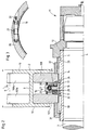
- als Einzelheit im Halbschnitt einen Richtzapfen einer Richtwelle einer Rollenrichtmaschine mit zwischen den Richtscheiben angeordnete Schneckenradantrieb;
Figur 2- eine der Figur 1 entsprechende Darstellung mit demgegenüber kleinerem, an die geringere Höhe des zu richtenden Trägers angepaßtem Schneckenrad des Schneckenradantriebes;
Figur 3- den Schneckenradantrieb gemäß Figur 1 entlang der Linie III-III geschnitten; und
Figur 4- eine der Figur 1 entsprechende Darstellung des Zapfenendes einer Richtwelle mit demgegenüber außerhalb der Richtscheiben angeordnetem Schneckenradantrieb, im Teilquerschnitt dargestellt.
- Figure 1
- as a detail in half section a straightening pin of a straightening shaft of a roller straightening machine with worm wheel drive arranged between the straightening disks;
- Figure 2
- a representation corresponding to Figure 1 with a smaller, adapted to the lower height of the support to be adjusted worm gear of the worm gear;
- Figure 3
- cut the worm wheel drive according to Figure 1 along the line III-III; and
- Figure 4
- a representation corresponding to Figure 1 of the pin end of a straightening shaft with the worm gear drive, on the other hand, arranged outside the straightening disks, shown in partial cross section.
Von einer einer nicht dargestellten Trägerstraße zum Warmwalzen von H-Trägern 1, 2 nachgeschalteten, obere und untere Richtwellen 3 besitzenden Rollenrichtmaschine sind in den Figuren 1 und 2 im wesentlichen lediglich die Richtzapfen 4 gezeigt. Auf dem Richtzapfen 4 ist eine Montage- bzw. Flanschbuchse 5 angeordnet, die zwei entsprechend dem Kammermaß 6 des Trägers 1 bzw. 2 voneinander beabstandete Richtscheiben 7, 8 bzw. 107, 108 (vgl. Figur 2) trägt; angedeutet sind auch die von oben her gegen den Steg 9 des Trägers 1 bzw. 2 angestellten Richtscheiben 7a, 8a bzw. 107a, 108a. Außerdem liegen die Richtscheiben den auf ihren Flanschen 10 in die Richtmaschine einlaufenden Trägern 1 bzw. 2 von den Innenseiten der Flansche 10 her an.In FIG. 1 and 2, essentially only the straightening
Die Montagebuchse 5 - und ebenso die Richtscheiben 7, 8 bzw. 107, 108 - ist mit dem Richtzapfen 4 mit Hilfe eines von dem freien Zapfenende her auf die Richtwelle 3 aufgesetzten Spannkopfes 11 verspannt; von dem durch einen Pfeil symbolisch angedeuteten Spannkopf 11 ist in den Figuren 1 und 2 lediglich ein den Richtzapfen 4 übergreifender Buchsenkörper 12 gezeigt. Die Montagebuchse 5 ist mit Paßfedern 13, 14 versehen, die gleichzeitig als Paßfeder-Führungen zum axialen Verschieben der Richtscheiben 7, 8 bzw. 107, 108 dienen. Zwischen den Richtscheiben 7, 8 bzw. 107, 108 ist ein Schneckenradantrieb 15 bzw. 16 (vgl. Figur 2) angeordnet. Dieser besteht aus einem auf Wälzkörpern 17 der Montagebuchse 5 gelagerten Schneckenrad 18 bzw. 19 und einer damit kämmenden, in einem Schneckengehäuse 20 angeordneten Schnecke 21. Um das Schneckenrad 18 bzw. 19 in Drehung zu versetzen, kann - wie sich aus Figur 3 ergibt - auf einen Zapfen 22 der Schnecke 21 ein Handrad oder ein Elektro- oder Preßluftschrauber aufgesteckt werden. Das Schneckenrad besitzt beidseitig Radnaben 23, die mit einem als Trapezgewinde ausgebildeten Außengewinde 24 versehen sind. Diese kämmen mit entsprechenden Innengewinden 25 von Ringhülsen 26, die über Schraubverbindungen 27 an den Richtscheiben 7, 8 bzw. 107, 108 festgelegt sind.The mounting bush 5 - and also the straightening
Wie in Figur 1 gezeigt ist, ist die dort der inneren Richtscheibe 7 zugeordnete Ringhülse 26 über eine Momentenstütze 28 mit dem Schneckengehäuse 20 verbunden. Das Schneckenrad 18 bzw. 19 läuft mit seinem in das Schneckengehäuse 20 hineinragenden Teil in dort angeordneten Wälzkörpern 29, und der Abstand zwischen den Richtscheiben 7, 8 bzw. 107, 108 und dem Schneckengehäuse 20 wird von Faltenbälgen 30 überbrückt. Jeweils von den Außenseiten her gegen die Richtscheiben 7, 8 bzw. 107, 108 angestellte Gewinderinge 31, 32 sind auf entsprechende Gewindeabschnitte der Montagebuchse 5 bis völlig zur Anlage gegen die Richtscheiben 7, 8 bzw. 107, 108 aufgeschraubt; der äußere Gewindering 32 ist zudem auf einer Paßfeder 33 angeordnet.As shown in FIG. 1, the
Sollen die Richtscheiben 7, 8 bzw. 107, 108 auf einen entweder kleineren oder größeren Abstand zueinander verstellt werden, was abhängig ist von der geänderten Dicke der Flansche 11 des einlaufenden Trägers 1 bzw. 2, so wird mittels Spannkopf 11 zunächst die Verspannung der Richtscheiben gelöst und die Schnecke 20 und damit das Schneckenrad 18 bzw. 19 verdreht. Dabei verschieben sich - im Falle der Verkleinerung des Abstandes der Richtscheiben - die Ringhülsen 26 mit den dazugehörigen Richtscheiben 7, 8 bzw. 107, 108 nach innen, das heißt, sie bewegen sich aufeinanderzu. Ist der gewünschte Abstand eingestellt, der sich bspw. mit einer Schablone oder Schiebelehre kontrollieren läßt, werden die Gewindemuttern 31, 32 nachgestellt, bis sie an den Außenflächen der Richtscheiben anliegen. Danach wird mit Hilfe des Spannkopfes 11 die notwendige Verspannung wieder hergestellt.If the straightening
Werden hingegen - wie in Figur 2 dargestellt - Träger 2 mit einem von dem vorher eingelaufenen Träger baureihenabhängig wesentlich geringerem oder größerem Höhenmaß 34 gerichtet, muß beim Umbau ein neues Schneckenrad 19 montiert werden. Bei dem Ausführungsbeispiel nach Figur 2 ist das Höhenmaß 34 des Trägers 2 wesentlich kleiner als das des Trägers 1, so daß entsprechend das Schneckenrad 19 weniger breit als das Schneckenrad 18 gemäß Figur 1 ist. Für die beschriebene Verschiebetechnik ist das Höhenmaß des gerade einlaufenden Trägers jedoch ohne Belang, das heißt, die Abläufe finden stets in gleicher Weise statt.On the other hand, if - as shown in FIG. 2 -
Bei der Ausführung eines Schneckenradantriebes 35 zum Verändern des Abstandes zwischen Richtscheiben 36, 37 gemäß Fig. 4 sind mit den in den Figuren 1 bis 3 gezeigten übereinstimmende Bauteile mit denselben Bezugsziffern versehen. Der Schneckenradantrieb 35 ist hier der äußeren Richtscheibe 37 vorgelagert, das heißt dem Ende des Richtzapfens 4 zugewandt angeordnet. Die von einem Motor 38 angetriebene Schnecke 39 ist in dem Buchsenkörper 12 des Spannkopfes 11 gelagert, und auch das Schneckenrad 40 ist in dem Buchsenkörper 12 angeordnet. Das Schneckenrad 40 ist mit einem Innengewinde 41 versehen, das mit einem Außengewinde 42 einer auf einer Paßfeder 43 der Montagebuchse 5 geführten Verschiebebuchse 44 kämmt. Die in Figur 4 linke, innere Richtscheibe 36 ist gegen einen Bund 45 der Montagebuchse 5 verspannt, und von der Innenfläche her liegt ihr ein auf die Montagebuchse 5 geschraubter Gewindering 46 an; die Richtscheibe 36 ist stationär angeordnet, das heißt, sie läßt sich nicht verschieben. Hingegen kann die auf der Verschiebebuchse 44 zwischen einem von innen her aufgeschraubten Gewindering 47 und außen angelegten Beilagen 48 befestigte Richtscheibe 37 bei sich ändernder Dicke der Flansche 10 des Trägers 49 bzw. bei einem aus einer anderen Baureihe einlaufenden Träger mit einem demgegenüber wesentlich geänderten Höhenmaß 34 axial verschoben werden. Hierzu ist es lediglich erforderlich, mittels des Motors 38 die Schnecke 39 und damit das Schneckenrad 40 anzutreiben, dessen Drehbewegung sich aufgrund der miteinander kämmenden Gewinde 41 des Schneckenrades 40 bzw. 42 der Verschiebebuchse 44 in eine translatorische Bewegung umwandelt, wozu der Verschiebebuchse 44 eine außerdem an dem Buchsenkörper 12 befestigte Momentenstütze 50 zugeordnet ist. Es versteht sich, daß - wie im Zusammenhang mit den Figuren 1 und 3 beschrieben - bei Vestellbewegungen die von dem Spannkopf 11 aufgebrachte Verspannung zunächst gelöst und anschließend wieder hergestellt werden muß.In the embodiment of a
- 11
- RichtwelleStraightening wave
- 2, 2a2, 2a
- RichtscheibeStraightening disc
- 3, 3a3, 3a
- RichtscheibeStraightening disc
- 44th
- RichtzapfenStraightening pin
- 55
- H-TrägerH-beam
- 66
- SpannkopfClamping head
- 77
- MontagebuchseAssembly bushing
- 88th
- PaßfederführungFeather key guide
- 99
- BauhöheOverall height
- 1010th
- Stegweb
- 1111
- Flanschflange
- 1212th
- KammermaßChamber size
- 1313
- Paßfederadjusting spring
- 1414
- Beilagegarnish
- 1515
- H-TrägerH-beam
- 1616
- BuchsenkörperSocket body
- 1717th
- FaltenbalgBellows
- 1818th
- VerschiebeeinheitDisplacement unit
- 1919th
- Innengewindeinner thread
- 2020th
- Muttermother
- 2121
- KammerbohrungChamber bore
- 2222
- KammerbohrungChamber bore
- 2323
- HydraulikzylinderHydraulic cylinder
- 2424th
- StellkolbenAdjusting piston
- 2525th
- AußengewindeExternal thread
- 2626
- AxialbohrungAxial bore
- 2727
- GewindebolzenThreaded bolt
- 2828
- HülseSleeve
- 2929
- DruckraumPressure room
- 3030th
- QuerbohrungCross hole
- 3131
- RingleitungLoop
- 3232
- RingleitungLoop
- 3333
- RingleitungLoop
- 3535
- DruckraumPressure room
- 36a, 36b36a, 36b
- DruckraumPressure room
- 3737
- AnschlußConnection
- 3838
- VerteilerbohrungDistributor hole
- 3939
- WeggeberDisplacement sensor
Claims (9)
dadurch gekennzeichnet,
daß zur Richtscheibenverschiebung ein Schneckenradantrieb (15, 16; 35) eingesetzt ist.Straightening machine for rolled beams, in particular H-beams, in which at least one of the two straightening disks, which lie against the inside of the beam flanges and are supported by a straightening shaft, can be adjusted axially,
characterized,
that a worm gear drive (15, 16; 35) is used for shifting the directional disk.
dadurch gekennzeichnet,
daß die Richtscheibe (n) (7, 8 bzw. 107, 108) fest mit einer von dem Schneckenradantrieb (15, 16; 35) beaufschlagten Ringhülse (26) bzw. Verschiebebuchse (44) verbunden ist (sind).Straightening machine according to claim 1,
characterized,
that the straightening disc (s) (7, 8 or 107, 108) is (are) firmly connected to an annular sleeve (26) or displacement sleeve (44) acted upon by the worm gear drive (15, 16; 35).
dadurch gekennzeichnet,
daß das Schneckenrad (18, 19) zwischen den Richtscheiben (7, 8 bzw. 107, 108) auf einer den Richtzapfen (4) der Richtwelle (3) umschließenden Montagebuchse (5) gelagert ist und beidseitig Radnaben (23) besitzt, die mit einem entsprechenden Innengewinde (25) der Ringhülsen (26) kämmende Außengewinde (24) aufweisen.Straightening machine according to claim 1 or 2,
characterized,
that the worm wheel (18, 19) is mounted between the straightening discs (7, 8 and 107, 108) on a mounting bush (5) surrounding the straightening pin (4) of the straightening shaft (3) and has wheel hubs (23) on both sides, which with have a corresponding internal thread (25) of the ring sleeves (26) meshing external thread (24).
dadurch gekennzeichnet,
daß jede Ringhülse (26) über eine Schraubverbindung (27) an der zugehörigen Richtscheibe (7, 8 bzw. 107, 108) befestigt ist.Straightening machine according to one or more of claims 1 to 3,
characterized,
that each ring sleeve (26) is attached via a screw connection (27) to the associated straightening disk (7, 8 or 107, 108).
dadurch gekennzeichnet,
daß das Schneckengehäuse (20) über eine Momentenstütze (28) mit einer Ringhülse (26) verbunden ist.Straightening machine according to one or more of claims 1 to 4,
characterized,
that the worm housing (20) is connected to an annular sleeve (26) via a torque support (28).
dadurch gekennzeichnet,
daß das Schneckenrad (40) mit Abstand vor der äußeren, dem freien Ende der Richtwelle (3) zugewandten Richtscheibe (37) im Buchsenkörper (12) eines Spannkopfes (11) angeordnet ist und einerseits mit der im Buchsenkörper (12) gelagerten Schnecke (39) und andererseits über ein Innengewinde (41) mit einem Außengewinde (42) der Verschiebebuchse (44) kämmt.Straightening machine according to claim 1 or 2,
characterized,
that the worm wheel (40) is arranged at a distance in front of the outer straightening disk (37) facing the free end of the straightening shaft (3) in the socket body (12) of a clamping head (11) and on the one hand with the worm (39) mounted in the socket body (12) ) and, on the other hand, meshes with an external thread (42) of the sliding bushing (44) via an internal thread (41).
gekennzeichnet durch
einen die Schnecke (39) antreibenden Motor (38).Straightening machine according to claim 6,
marked by
a motor (38) driving the worm (39).
dadurch gekennzeichnet,
daß die Verschiebebuchse (44) bzw. die axialbeweglichen Richtscheiben (7, 8 bzw. 107. 108) auf Paßfederführungen (13, 14; 43) der Montagebuchse (5) angeordnet ist bzw. sind.Straightening machine according to one or more of claims 1 to 7,
characterized,
that the sliding bush (44) or the axially movable straightening disks (7, 8 or 107, 108) are arranged on feather key guides (13, 14; 43) of the mounting bush (5).
dadurch gekennzeichnet,
daß die axialbeweglichen Richtscheiben (7, 8 bzw. 107, 108) mit einem Spannkopf (11) gegen Gewinderinge (31, 32) verspannt sind.Straightening machine according to one or more of claims 1 to 8,
characterized,
that the axially movable straightening disks (7, 8 or 107, 108) are braced with a clamping head (11) against threaded rings (31, 32).
Applications Claiming Priority (2)
| Application Number | Priority Date | Filing Date | Title |
|---|---|---|---|
| DE4323468A DE4323468A1 (en) | 1993-07-14 | 1993-07-14 | Straightening machine for rolled beams, especially H-beams |
| DE4323468 | 1993-07-14 |
Publications (2)
| Publication Number | Publication Date |
|---|---|
| EP0634235A1 true EP0634235A1 (en) | 1995-01-18 |
| EP0634235B1 EP0634235B1 (en) | 1997-12-10 |
Family
ID=6492713
Family Applications (1)
| Application Number | Title | Priority Date | Filing Date |
|---|---|---|---|
| EP94110510A Expired - Lifetime EP0634235B1 (en) | 1993-07-14 | 1994-07-06 | Straightening machine for rolled profiles, especially H-profiles |
Country Status (7)
| Country | Link |
|---|---|
| EP (1) | EP0634235B1 (en) |
| JP (1) | JPH07144225A (en) |
| KR (1) | KR100291164B1 (en) |
| CN (1) | CN1057947C (en) |
| AT (1) | ATE160956T1 (en) |
| DE (2) | DE4323468A1 (en) |
| ES (1) | ES2110658T3 (en) |
Cited By (3)
| Publication number | Priority date | Publication date | Assignee | Title |
|---|---|---|---|---|
| US6823707B2 (en) | 2002-04-04 | 2004-11-30 | Abl Fabricators, Inc. | Mobile flange press and method |
| CN104353704A (en) * | 2014-11-11 | 2015-02-18 | 无锡恒富科技有限公司 | Pressing wheel lifting mechanism of straightening machine |
| CN110449462A (en) * | 2019-08-17 | 2019-11-15 | 陶忠梅 | A kind of profile rolls rear finishing process |
Families Citing this family (7)
| Publication number | Priority date | Publication date | Assignee | Title |
|---|---|---|---|---|
| CN100588476C (en) * | 2006-12-25 | 2010-02-10 | 西安重型机械研究所 | Tension mechanism for profiled bar pressure straightening device |
| CN101712045B (en) * | 2009-12-15 | 2012-07-04 | 攀钢集团钢铁钒钛股份有限公司 | Method for rolling H-shaped steel |
| CN104307932A (en) * | 2014-11-11 | 2015-01-28 | 无锡恒富科技有限公司 | Transmission mechanism of straightening machine pressure roller lifting component |
| CN106825123B (en) * | 2016-12-30 | 2018-09-21 | 无锡华联科技集团有限公司 | The horizontal straightening machine of H profile steel |
| CN112570479B (en) * | 2020-11-11 | 2023-02-10 | 山东大业股份有限公司 | Straightening device used before surface treatment of tire bead steel wire |
| DE102020215582A1 (en) | 2020-12-09 | 2022-06-09 | Sms Group Gmbh | bending device |
| WO2023138888A1 (en) | 2022-01-24 | 2023-07-27 | Sms Group Gmbh | Straightening machine and method for straightening a steel profile |
Citations (4)
| Publication number | Priority date | Publication date | Assignee | Title |
|---|---|---|---|---|
| DE431332C (en) * | 1925-02-14 | 1926-07-05 | Sack Gmbh Maschf | Straightener with overhung rollers |
| DE3522976A1 (en) * | 1985-06-27 | 1987-01-08 | Schloemann Siemag Ag | Method and apparatus for straightening rolling stock |
| JPS62176604A (en) * | 1986-01-30 | 1987-08-03 | Nippon Steel Corp | Roll width adjuster |
| EP0472765A1 (en) * | 1990-08-28 | 1992-03-04 | Kawasaki Steel Corporation | Section steel straightener with adjustable roller width |
-
1993
- 1993-07-14 DE DE4323468A patent/DE4323468A1/en not_active Withdrawn
-
1994
- 1994-07-06 ES ES94110510T patent/ES2110658T3/en not_active Expired - Lifetime
- 1994-07-06 EP EP94110510A patent/EP0634235B1/en not_active Expired - Lifetime
- 1994-07-06 DE DE59404764T patent/DE59404764D1/en not_active Expired - Fee Related
- 1994-07-06 AT AT94110510T patent/ATE160956T1/en not_active IP Right Cessation
- 1994-07-11 JP JP6158953A patent/JPH07144225A/en active Pending
- 1994-07-14 KR KR1019940016955A patent/KR100291164B1/en not_active IP Right Cessation
- 1994-07-14 CN CN94108596A patent/CN1057947C/en not_active Expired - Fee Related
Patent Citations (4)
| Publication number | Priority date | Publication date | Assignee | Title |
|---|---|---|---|---|
| DE431332C (en) * | 1925-02-14 | 1926-07-05 | Sack Gmbh Maschf | Straightener with overhung rollers |
| DE3522976A1 (en) * | 1985-06-27 | 1987-01-08 | Schloemann Siemag Ag | Method and apparatus for straightening rolling stock |
| JPS62176604A (en) * | 1986-01-30 | 1987-08-03 | Nippon Steel Corp | Roll width adjuster |
| EP0472765A1 (en) * | 1990-08-28 | 1992-03-04 | Kawasaki Steel Corporation | Section steel straightener with adjustable roller width |
Non-Patent Citations (1)
| Title |
|---|
| PATENT ABSTRACTS OF JAPAN vol. 12, no. 18 (M - 660)<2865> 20 January 1988 (1988-01-20) * |
Cited By (3)
| Publication number | Priority date | Publication date | Assignee | Title |
|---|---|---|---|---|
| US6823707B2 (en) | 2002-04-04 | 2004-11-30 | Abl Fabricators, Inc. | Mobile flange press and method |
| CN104353704A (en) * | 2014-11-11 | 2015-02-18 | 无锡恒富科技有限公司 | Pressing wheel lifting mechanism of straightening machine |
| CN110449462A (en) * | 2019-08-17 | 2019-11-15 | 陶忠梅 | A kind of profile rolls rear finishing process |
Also Published As
| Publication number | Publication date |
|---|---|
| DE59404764D1 (en) | 1998-01-22 |
| CN1100975A (en) | 1995-04-05 |
| KR100291164B1 (en) | 2001-06-01 |
| ATE160956T1 (en) | 1997-12-15 |
| ES2110658T3 (en) | 1998-02-16 |
| JPH07144225A (en) | 1995-06-06 |
| CN1057947C (en) | 2000-11-01 |
| DE4323468A1 (en) | 1995-01-19 |
| EP0634235B1 (en) | 1997-12-10 |
Similar Documents
| Publication | Publication Date | Title |
|---|---|---|
| AT411020B (en) | ROLLING STAND FOR ROLLING MILLS FOR ROLLING METAL TUBES, RODS OR WIRE | |
| EP0634235B1 (en) | Straightening machine for rolled profiles, especially H-profiles | |
| DE3609290A1 (en) | BEARING ROLLER | |
| DE10015339A1 (en) | Roll stand for rolling mills for rolling metallic pipes, bars or wires | |
| WO2001097992A1 (en) | Section straightening machine | |
| EP3664998B1 (en) | Press | |
| EP0563699B1 (en) | Plate cylinder with adjustable tension bar | |
| EP0721810B1 (en) | Straightening machine for rolled beams, in particular hyper-beams | |
| DE2720673B2 (en) | Device for uneven tensioning of a rubber blanket in an offset printing machine | |
| EP0203279B1 (en) | Cylinder, preferably impression cylinder of a forme cylinder, the sleeve of which can be bent | |
| EP0953385B1 (en) | Straightening machine for rolled beams | |
| DE4442568B4 (en) | Width-adjustable horizontal roller for a universal roll stand | |
| DE4232407C2 (en) | Device for straightening hot-rolled beams or U-profiles | |
| DE3135610A1 (en) | Device for adjusting lengthened support sections, in particular on machines such as concrete pumps or the like | |
| DE10144743B4 (en) | Roll stand for rolling rod or tubular material | |
| DE19509768C2 (en) | camp | |
| DE4330649C2 (en) | Profile roll straightening machine with overhung straightening rolls | |
| DE463891C (en) | Device for mounting the rolls in rolling mills | |
| EP0326805B1 (en) | Roll stand with a shifting device | |
| DE10300785B4 (en) | Hydraulic adjusting cylinder for roll gap adjustment | |
| EP2158047A1 (en) | Multipart roller | |
| EP0484781B1 (en) | Slab upsetting press for hot wide strip rolling mills | |
| WO2023138888A1 (en) | Straightening machine and method for straightening a steel profile | |
| WO2009080429A1 (en) | Anti-friction bearing for a tensioning and/or deflection roller | |
| DE2264713C3 (en) | Three-roll piercing mill |
Legal Events
| Date | Code | Title | Description |
|---|---|---|---|
| PUAI | Public reference made under article 153(3) epc to a published international application that has entered the european phase |
Free format text: ORIGINAL CODE: 0009012 |
|
| 17P | Request for examination filed |
Effective date: 19940801 |
|
| AK | Designated contracting states |
Kind code of ref document: A1 Designated state(s): AT DE ES IT SE |
|
| 17Q | First examination report despatched |
Effective date: 19960223 |
|
| GRAG | Despatch of communication of intention to grant |
Free format text: ORIGINAL CODE: EPIDOS AGRA |
|
| GRAG | Despatch of communication of intention to grant |
Free format text: ORIGINAL CODE: EPIDOS AGRA |
|
| GRAH | Despatch of communication of intention to grant a patent |
Free format text: ORIGINAL CODE: EPIDOS IGRA |
|
| GRAH | Despatch of communication of intention to grant a patent |
Free format text: ORIGINAL CODE: EPIDOS IGRA |
|
| GRAA | (expected) grant |
Free format text: ORIGINAL CODE: 0009210 |
|
| AK | Designated contracting states |
Kind code of ref document: B1 Designated state(s): AT DE ES IT SE |
|
| REF | Corresponds to: |
Ref document number: 160956 Country of ref document: AT Date of ref document: 19971215 Kind code of ref document: T |
|
| REF | Corresponds to: |
Ref document number: 59404764 Country of ref document: DE Date of ref document: 19980122 |
|
| REG | Reference to a national code |
Ref country code: ES Ref legal event code: FG2A Ref document number: 2110658 Country of ref document: ES Kind code of ref document: T3 |
|
| ITF | It: translation for a ep patent filed |
Owner name: STUDIO JAUMANN P. & C. S.N.C. |
|
| PLBE | No opposition filed within time limit |
Free format text: ORIGINAL CODE: 0009261 |
|
| STAA | Information on the status of an ep patent application or granted ep patent |
Free format text: STATUS: NO OPPOSITION FILED WITHIN TIME LIMIT |
|
| 26N | No opposition filed | ||
| PGFP | Annual fee paid to national office [announced via postgrant information from national office to epo] |
Ref country code: ES Payment date: 20010716 Year of fee payment: 8 |
|
| PGFP | Annual fee paid to national office [announced via postgrant information from national office to epo] |
Ref country code: SE Payment date: 20020625 Year of fee payment: 9 |
|
| PG25 | Lapsed in a contracting state [announced via postgrant information from national office to epo] |
Ref country code: ES Free format text: LAPSE BECAUSE OF NON-PAYMENT OF DUE FEES Effective date: 20020707 |
|
| PGFP | Annual fee paid to national office [announced via postgrant information from national office to epo] |
Ref country code: AT Payment date: 20030703 Year of fee payment: 10 |
|
| PG25 | Lapsed in a contracting state [announced via postgrant information from national office to epo] |
Ref country code: SE Free format text: LAPSE BECAUSE OF NON-PAYMENT OF DUE FEES Effective date: 20030707 |
|
| EUG | Se: european patent has lapsed | ||
| REG | Reference to a national code |
Ref country code: ES Ref legal event code: FD2A Effective date: 20030811 |
|
| PG25 | Lapsed in a contracting state [announced via postgrant information from national office to epo] |
Ref country code: AT Free format text: LAPSE BECAUSE OF NON-PAYMENT OF DUE FEES Effective date: 20040706 |
|
| PGFP | Annual fee paid to national office [announced via postgrant information from national office to epo] |
Ref country code: DE Payment date: 20060714 Year of fee payment: 13 |
|
| PGFP | Annual fee paid to national office [announced via postgrant information from national office to epo] |
Ref country code: IT Payment date: 20060731 Year of fee payment: 13 |
|
| PG25 | Lapsed in a contracting state [announced via postgrant information from national office to epo] |
Ref country code: DE Free format text: LAPSE BECAUSE OF NON-PAYMENT OF DUE FEES Effective date: 20080201 |
|
| PG25 | Lapsed in a contracting state [announced via postgrant information from national office to epo] |
Ref country code: IT Free format text: LAPSE BECAUSE OF NON-PAYMENT OF DUE FEES Effective date: 20070706 |